
Boxford 125TCL CNC Upgrade
by John
This small CNC lathe was converted from the original c1985 electronics, to components which are compatible with a PC running Windows XP and Mach3.
Reader Paul M asked about circuit diagrams. I must confess that I do not have such. Indeed, I would not understand them. The electronic connections were made by my expert friend Stuart T. I believe that Stuart intends to write up the conversion for one of the Australian magazines, and possibly this post might give him a gentle shove~.
In passing, I should give Stuart a thumbs up for his excellent CNC lathe program, which is far superior, in my opinion, than Mach3 for running the CNC lathe. It is called Ezilathe and is available as a free download.
Anyway Paul, here are the promised photographs of the electronic components of the Boxford, after the conversion. You should be able to work out many of the connections by zooming in.
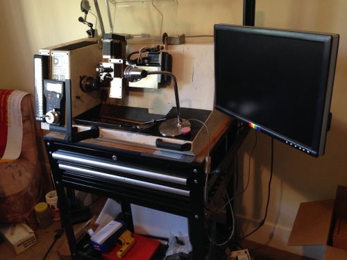
The Boxford 125TCL sitting on a bought trolley which could have been made to measure. The PC is on the bottom shelf, the extra toolholders and tools in the drawers, the wireless MPG on the front, and upgraded stepper motors in black.

The rear view to show the extra power outlets to supply the screen and PC. I still operate this lathe in a spare bedroom of my house. Very handy if I have a sleepless night. It is so quiet that it does not disturb SWMBO.

The view with the back open. The only components from the original setup are the spindle motor, the main switch, and the Gemini controller (RHS with orange cover).
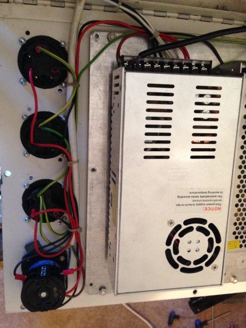
Power outlets, main switch and power supply.
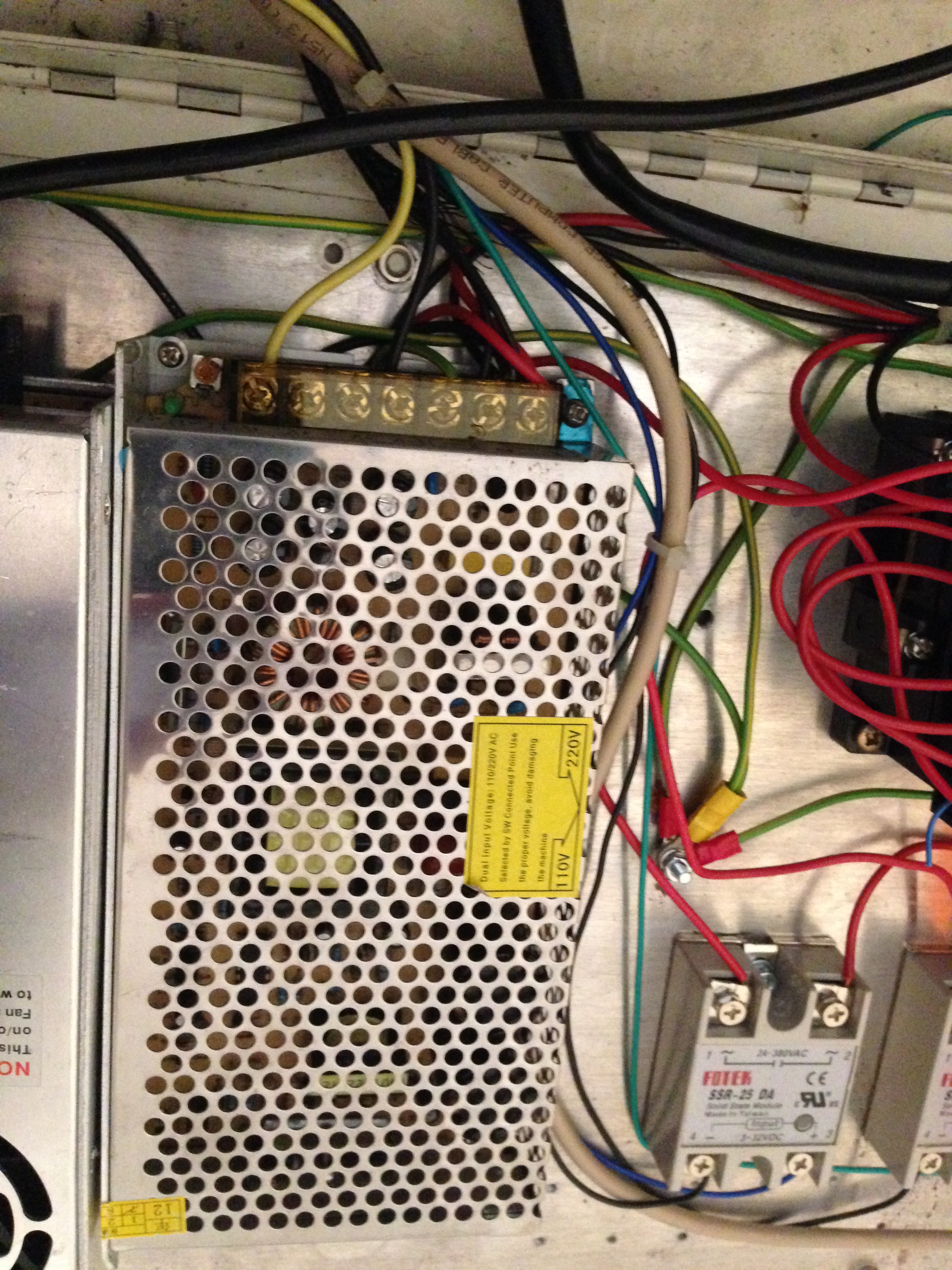
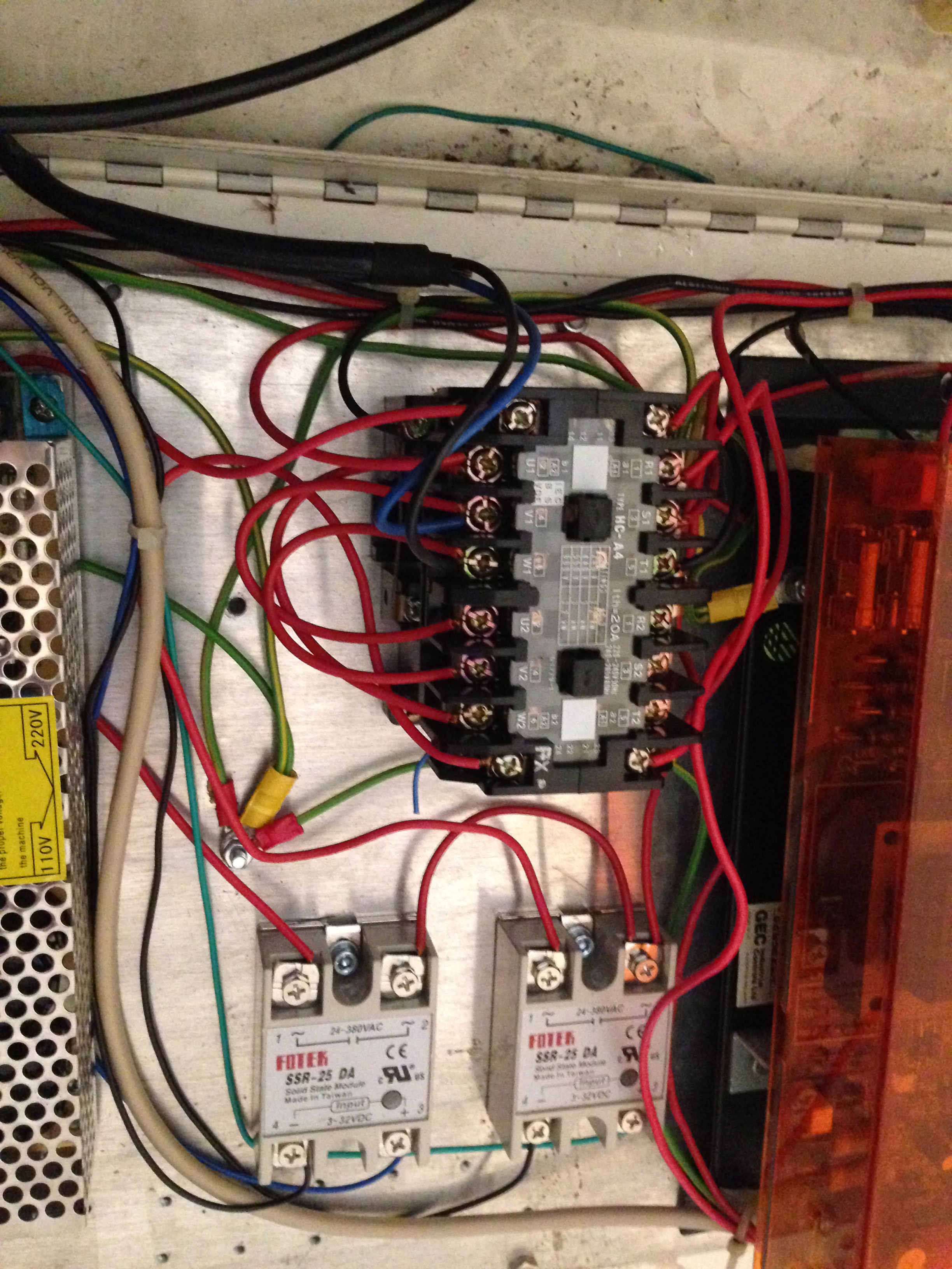
Transformer. Can’t remember what the Fotek is for.

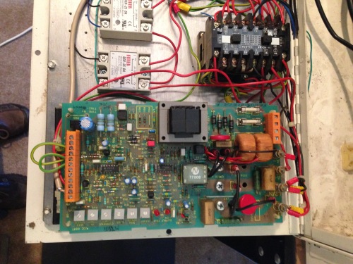
Gemini with cover removed.

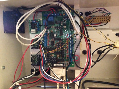
C11 R9 Breakout board, the optical indexer (top), and Gecko stepper drivers (LHS), parallel cable from the PC, all mounted on an aluminium plate.

Spindle motor, original. But now considering upgrading to a more powerful motor.

new cable junction box for the stepper cables.
New cooling fan, top LHS
So, I hope that these shots are some use. If you do not recognise the components, I suggest that you follow my example and bribe an expert friend to do the connections.

John,
Brilliant mate, if I ever get down your way I owe you a pot or two. The Fotek are relays. They switch the current from what I can understand.
Thank you
Paul
LikeLike
John,
Is there any chance you could put your friend Stuart and I in contact please. I am hoping he made some notes and took some photos when he was converting your machine with you.
Cheers
Paul
LikeLike
Paul, send me your contact details and I will pass them on to Stuart. I doubt that he has has notes. It is all in his head. John
LikeLike
Hi John,
Trying to get one of these upgraded in my school with a mate (we’re sixth form students) first thing we noticed is that the reversible switch cap has disappeared. There is the switch itself on the inside but the cap is nowhere to be seen. Does the switch just control the main on/off mechanism or is there another functionality as I can see 3 bits of info near the switch on your lathe.
Cheers,
Tom
LikeLike
Hi Tom, Please send a photo of the switch so I can identify it. John
LikeLike
It is the master switch at the back, but I will do tomorrow when I am back. Tom
LikeLike
Hi John, here I the switch I was talking about http://imgur.com/OqPpGtv
Tom.
LikeLike
Hi Tom, it is on on -off switch. The third symbol is not a switch position. Good luck with the project. John (I will post a photo on the blog)
LikeLike
John, thanks for the clarification, thought that was the case. Also, can you possibly supply a circuit diagram? Tom
LikeLike
Tom unfortunately I do not have a circuit diagram, but there are a number of photographs of the wiring arrangements in a blog from about 6-12 months ago. John
LikeLike
Thanks John, I’ll have a look for it. Tom
LikeLike
Sir, I need connection diagram for this Gemini controller.
Thanks
LikeLike
Hello Kushal Sharma
I have a Gemini controller manual. If you send me an email address I will send you a pdf copy. John
LikeLike
Hi John,
Thoroughly enjoying your work!
I have just started on a Boxford260 VMC and am desperately looking for the GEC Gemini manual. Would you be able to send it to me? it would be hugely appreciated.
Many thanks
Luc
LikeLike
Hi Luc. No problem except that I will need an email address to send the electronic file (pdf from memory).. John
LikeLike
Hello John I too have a boxford 125 which I would like to upgrade, any information would be most helpful thanks
Erroll
LikeLike
Erroll, I suggest that you do a search of my posts using “Boxford” and “CNC” as search terms. Then decide what you intend to do. I was lucky to have a friend who is expert in CNC and electronic matters. I would not have succeeded in the conversions without his knowledge and help. Even so, it has been a lot of time and effort.
If you get specific questions and problems I am happy to help if I can.
There is almost nothing remaining of the original electronics, steppers, spindle drive, pulleys and belts and ball screws. The boxford bed, cross slide, toolpost and cabinet is just about all that remains of the original machine. But I must say that the end result has been worth the effort.
John
LikeLike
Hi there John.
sorry if I’m in the wrong place to ask questions, but I can’t find anyone to ask about the Boxford 125 TCL.
I have one that belonged to an uncle and I’m getting rid of it (selling).
but I plugged it in (been stood for years) and a capacitor popped on the pcb that has the clear orange cover on it.
do you know of anyone who has a schematic for this as it has destroyed the cap and I don’t know what value it is.
my email
any information would be much appreciated. Thank you.
kindest regards.
drew.
LikeLike
Thank you sir for this wonderful gift. I wasn’t getting it any where on internet. Thanks for this wonderful help.
Regards,
Kushal.
LikeLike
Glad to help. Regards, John.
LikeLike
Hi John
Any chance of a copy of the Gemini controller manual please?
I’m in the process of a 125 rebuild.
Regards
Peter
LikeLike
Sure. Send me an email address. John
LikeLike
pscnc@mail.com
Regards
Peter
LikeLike
Gemini Controller Manual sent. Good luck with the rebuild. John.
LikeLike
Hi John, i’m rebuilding a lovely little Tcl 125. read a few posts back about you have moved to a servo for the spindle I’d love to hear more about it. Do you still use the belt changes or is it now good torque through all the speeds? thanks for the blog btw. great read.
LikeLike
Hi Ben, I made a new pulley for the servo spindle motor and the range is now 300-3200 with excellent torque throughout so I cannot remember ever doing a belt change. The option for a belt change is still there, with lower speeds and even higher torques available. And thanks for the nice feedback. John
LikeLike
Thanks John I spent an hour this morning figuring out the belt size, its an optibelt VB 6-600 if you ever need one. I cant find a matching pulley off the shelf so may be able to modify the existing, though i haven’t looked at it properly yet. I don’t suppose it would be too difficult to make a new one though. Im really tempted to make the change to Servo, so feeling out what it involves before taking the plunge!
LikeLike
Hi Ben, you had asked about the speed control. Yes it is still the -10 to +10v, with the
-/+ determining the direction of rotation. If your spindle motor is original, I predict that you will eventually upgrade it. John
LikeLike
Hi John, great blog! For my sins I have gone and bought an old Boxford 260vmc, with similar original electrics to your lathe – 240v everywhere and am currently pondering an upgrade path that hopefully doesn’t end up killing me!
I have the Gemini spindle controller but no manual so I’d be extremely grateful if you would email me a copy?
My email address is dgarepp ‘at’ gmail.com.
Great photos by the way, they really help!
Regards David
LikeLike
Sure.
LikeLike
BTW, I eventually scrapped the Gemini and installed a new spindle motor and controller. See later posts.
LikeLike
Excellent, many thanks John. No doubt I’ll replace it the future but for now am going to try and get it running. At the moment any more expense on this thing and SWMBO will be on the warpath :).
LikeLike
Thanks for a most interesting blog. Ihave just started to renovate my Boxford 125 which is mechanically as new.any tips as to what to buy by way of stepper motor drivers etc would be most welcome ,also do you have access to a circuit diagram
LikeLike
No circuit diagram but there are photos of the connections in old posts on this site. Also the drivers, breakout board, relays, power supplies. I used a servo to replace the spindle motor. It is an excellent lathe and worth the effort. John
LikeLike
Ok thanks what type of servo motor & how is it driven? not happy with this wordpress arrangement, hope this time it works
LikeLike
H Jimmymouse, sorry for the delay, I have been away. The servo motor came from a Chinese ebay supplier fasttobuy2012. It is 750w, Nema 34 and comes with a controller. currently costs $US260. If you cannot locate it on ebay, send me your email address and I will send a link. John
LikeLike
Thanks for your reply John ,email duly posted
LikeLike
OK
LikeLike
please could you repeat the Nema motor details ,unfortunately I am having problems with anti spam . I did include my email details in the box below this but not sure how the system works
LikeLike
Sorry, which motor are you asking about? Not sure who is asking. Your email address was not included in the message.
LikeLike
Hi John,
I have found your web page inspirational to the level that I have bought a shell of a TCL 125 and have got one of the servo motors you recommended. My problem is that I cant figure out how to connect it to the breakout board. can you help some more with this.
I am also fascinated with how you did the positional control
Thanks Tom
LikeLike
Hi Tom, I replaced the spindle motor with an AC servo. More powerful, and able to be controlled for position as well as RPM. I think that I documented the changes in posts. John
LikeLike
Hi John,
Thank you for replying, I find your posts absolutely fantastic and incredibly interesting
Yes you covered a lot in your posts, but I also got one of these servo motors and was reading through the manual for it (which I found very complicated) I could figure out how to connect to the breakout board if I was to use it to move the axis but not how to do it as a spindle motor. There are also settings that appear to have to be changed in the menu on the controller. I’m not sure is it because of translation from Chinese to English or just that I don’t know enough about what is needed, or both but I just cant figure it out.
any help would be greatly appreciated
Regards
Tom
LikeLike
Tom, if you send me your email address I will send you the contact details for Stuart T, who was my expert advisor, and wiring expert. He is prepared to communicate with you and answer your questions. I gather that 2 extra connections are required for the angular control. John.
LikeLike
Hello John would you remember the current in amps & type of driver for the stepper motor drives? There are numerous ones available from China at reasonable prices, I just need to make sure before ordering
Thanks for your interesting blog & good luck with the casting
Jimmy
LikeLike
Hello John Please can you remember the type & current in amps required by the stepper motors. There are drivers available from China at reasonable prices obviously they need to be boss of the job
Many thanks for your interesting blogs
Jimmy
LikeLike
Hi, I don’t have a record of the stepper sizes.
The code on the stepper is 23HS30-28045
They are 56x56mm attachment plate, and 75mm long, which is the biggest stepper which I could fit in the limited space.
They are Nema 23, x3″ long. Knowing those dimensions you can get the amps from the manufacturers spec sheet online. If I can find the spec sheet I will send a copy. John
LikeLike
Hi John, been awhile since I last looked here. Is there any chance you could get Stuart T to label the components please. It would be a big help for novice home shop guys like me. By the way I really enjoy following the cannon builds, very interesting.
LikeLike
I can ask
LikeLike