johnsmachines

machines which I have made, am making, or intend to make, and some other stuff. If you find this site interesting, please leave a comment. I read every comment and respond to most. n.b. There is a list of my first 800 posts in my post of 17 June 2021, titled "800 Posts"

Category: CNC lathe

Soft Jaws

The bronze gears which I cast yesterday were cut off the tree with small bolt cutters, band saw and hack saw.   Then a belt sander to reduce the daggy bits.

P1074316

The gears, and the tree trunk and branches which will be remelted.

P1074317

The faces needed to be flattened in the lathe, but how to hold the rather thin, delicate, irregular gears?

Soft jaws.

Soft jaws made of aluminium, and exactly machined to match the external diameter of gear teeth, so there are multiple contact points, and minimal chance of damaging the teeth.  I made these soft jaws ages ago, for just this sort of job.

P1074318

The soft jaws are machined to exactly fit the workpiece.

The soft jaws may be used multiple times, machined to shape each time.  Very handy in this situation.

P1074319

The larger gears are good.  I silver soldered some extra material on one of them for the shaft, then turned the shaft to size .  But, holding the small pinion gear is more problematic.  I will need to machine a soft jaw with a taper to hold the teeth.  Next session.  I should have anticipated this situation and designed the gear with a shaft to be PLA printed as one piece.


Axles for a Cannon Carriage

How fascinating is that for a topic!

Well, I found it interesting.  Maybe says something about me.

My 2 carriages have 20 wheels and 20 axles between them.  Plus the 4 big ones under the chassis’.  I had made the wheels.  The axles required some planning and thought, after all, whatever I did was going to be repeated at least 20 times.

I decided on stainless steel for the axles, and brass for the end caps.  The originals were steel, but they will be painted, so the appearance of the metal is irrelevant.

First steps were to cut up 20 pieces of 5mm stainless steel, 25mm long, and drill 5mm holes in 12.7mm brass rod, and part off 20 pieces 5mm wide.  With a few spares.

P1074196

The the brass end caps need to finish 4mm wide, so there was a machining allowance of only 0.5mm on each face.  So the silver soldering of the 2 parts needed to be reasonably precise.

P1074197

To assist with keeping the brass disks square to the rods while soldering, I drilled some 5mm holes in an aerated concrete block, exactly 21mm deep.

P1074198

Fluxed the mating parts, and silver soldered 5 at a time.  Very quickly.  I could have used Loctite 620, but would have had to wait until it cured before machining.

P1074200

A soak in sulphuric acid for a few minutes, then a water rinse.

P1074202

Then turned the end cap shape on the Boxford TCL125

P1074204

P1074206


Not quite finished. M2 Holes to be drilled through the end caps, and threaded to the brackets.  I will use the CNC toolpost milling attachment which I made in 2019.  That might warrant a short video.

A short video.  Well, a bit over 5 minutes…


P1074217

The capscrews are not kosher.  The original cannons had large slot screws.  But will anyone notice?  (idea…  I could fill in the hex hole with JB Weld, and machine a slot?!).  Maybe.

In retrospect I could have done the entire shaping and drilling and milling of the brass end cap using the toolpost mill on the CNC lathe.   Would have been a lot more efficient.

Boxford TCL125 CNC Lathe, 3rd AXIS.

Below is a video which was recorded by my machining mentor friend, Stuart Tankard.  Stuart made a milling attachment for his Boxford CNC lathe, and he demonstrates it in the following video by making some lovely small valve control handles.

I followed in Stuart’s footsteps by making a similar attachment for my identical Boxford 125 CNC lathe, but I have not yet video’d it in action.  Not much point when Stuart’s video is so good.  I really like the absence of irrelevant, irritating music.  Just machining sounds.   Enjoy.   (if you want to see it full screen, copy the YouTube address from the settings icon).

Model Cannon Barrel. (T)rifling Thoughts.

My aim (as it were) in making this model cannon is to have a high visual quality exhibition piece.

It is a 1:10 scale model, 1866 Armstrong 80lb, rifled muzzle loader, blackpowder cannon.

One question which always arises is whether it will be actually fired.  My answer is that if it could be fired legally, it would be nice so I could make a video.  However, Australia has very strict gun control laws, (with which I totally agree), and I do not intend to flout those laws.  So this gun will not be capable of being fired.  It will have no touch hole.

To satisfy the visual appearance of a touch hole there will be a laser printed dot at the location.  Along with laser engraved Queen Victoria insignia, sight lines, etc.

But, it IS a rifled cannon, so I do intend to rifle the barrel.  And that needs to accomplished before the trunnions are fitted, and after the cascabel is fitted, so the orientation of the rifling is as per the original.

P1053354

The original rifling.  The 3 grooves are each 30mm wide, (clockwise or anticlockwise, not sure) and extend up to the edge of the powder chamber.  They are about 2 mm deep.  The powder chamber is slightly wider than the barrel bore, being continuous with the depth of the rifling grooves.  It is academic, because it will not be visible, but I will make it (the powder chamber, and the whole model) as accurately as I can, for my own satisfaction.  Fortunately the powder chamber is accessible to machining from the breech end, because the cascabel is screwed into position, and is removable.

Yesterday I started making the cascabel.  It was difficult.  The steel thread is lathe cut first, then the shape is lathe CNC’d.  Then there is milling the insides, and making a removable pinned rope retainer.  The third attempt was the most successful, but I am still not satisfied, and so there will be another one made today.   This is what I have so far…

P1053635

The turned barrel, threaded to accept the cascabel.  More work is required on the cascabel.

P1053642

The cascabel is mounted in an ER40 chuck.  It has been drilled and milled, and a removable insert is temporarily glued into place pending more machining.


Rifling.  Searching YouTube reveals multiple tools and setups from US sites.  Here are a few screen shots to show you some varieties.

From the sublime ….

Screen Shot 2020-02-16 at 8.29.10 am

to the other extreme…

Screen Shot 2020-02-16 at 8.39.12 am

No.  I will not be using a PVC pipe lash up.

The amateur designed and built machines are interesting….

Screen Shot 2020-02-15 at 9.15.27 am

Sine bar on the right.

Screen Shot 2020-02-16 at 8.23.12 am

Screen Shot 2020-02-16 at 8.24.24 am

Then there is the method of pressing a button cutter through the bore.  My bore is an odd size, so if I used this method I would need to make my own cutter.

Screen Shot 2020-02-16 at 8.36.35 am

Screen Shot 2020-02-16 at 8.29.57 am

This one is a computer animation of a 19th century rifling machine, now a museum exhibit.   Can you see the barrel?   Armstrong probably used a much larger version of this type to rifle his cannons.


But I think that I will use none of these methods.  I have a CNC mill and a CNC rotary table.  Mach3 can control both of these machines simultaneously.   If I mount the cutter assembly in the rotary table, and the cannon barrel to the mill quill, I should be able to cut the rifling grooves.  Still working on this one.

Armstrong RML barrel

After 3D printing a plastic 1:10 barrel I decided to have a go at turning one in steel.  I had a length of steel 70mm diameter and 290mm long, which was just too short to turn the entire barrel, so I decided to make one of the breech reduction rings separately, when I make the cascabel.

I did not know what the steel grade was, but it was off a machine so I thought that there would be a good chance that it would be reasonable quality.

P1053584

The length of rod next to the printed barrel.

The turning was initially fairly routine.

P1053594

and I was really pleased with the finish which was appearing.

P1053597

Mountains of hot swarf.

P1053600

The roughed out barrel.  I used the 16mm drill bit to drill the bore from both ends, but there was still 50mm or so beyond the reach of the bit.  So I silver soldered the drill bit into a length of silver steel (drill rod).

P1053604

And quickly completed the drilled hole. 

P1053606

Then transferred the piece to the CNC lathe, and shaped the barrel exterior.

I experienced 2 problems with the CNC turning.  The tapered chase of the barrel, and the rounded fillets came out really well, but the straight sections of the breech developed chatter marks.  I was preparing to take a skim to remove the chatter marks when I bumped the manual CNC control, the cutter dug in, and I got a deep score in the breech.  And broke the carbide cutter.  I turned away the dig in, but it left the breech diameter 3.5mm undersize.

I have no more steel of that size, and it will be quite a while before I get an opportunity to buy some.  So I persisted with the slightly undersized barrel.  It will be 62mm diameter rather than the intended 65.5mm.   I still have not decided whether to scrap it and start again.  But if I can get some more suitable steel I will remake it.  I might even use the undersized barrel to make a 64lb Armstrong RML, which had a smaller diameter breech than the 80lb RML which I am making.  (note added 19 Jan 2021…  The Armstrong 64pd and 80pd barrels had the SAME dimensions.  The main difference was that the inner tube of the 64pd guns coiled iron, but in the 80pd guns was solid ended steel. “Naval Gunnery” Garbett pp52-53).

P1053610

I showed it to SWMBO.  “That is beautiful” she said, somewhat to my surprise, and being surprised by its 3.5kg weight. 

P1053614

Ah…  if only…

Lathe Toolpost Milling attachment (CNC)


Although my recent posts indicate that I have spent  a fair amount of time recently on Google Earth Pro, I have also been busy in the workshop.  Mainly finishing the toolpost milling attachment for the Boxford CNC lathe, but also fiddling with the laser attachment for the CNC mill.  Neither of those projects is completely finished, but I thought that you might be interested in some progress photos.

IMG_8279

This is what the Boxford TCL125 CNC lathe now looks like from the front.  It is substantially modified from the original which I purchased 5 years ago.  To mention a few changes…..

the axis stepper motors are bigger and more powerful than the originals

the ball screws are now 10mm diameter, compared with the original 8mm

there are some adjustable axis limit switches

the 3 jaw chuck is replaced by an ER32 collet chuck

there is a removable toolpost milling attachment with ER 16 Collet chuck, with a speed controller, cables, and panic switch.

there is a removable safety screen (not seen in the photo)

And hidden in the electronics compartment….

IMG_8278.JPG

There is a 750 watt AC Servo spindle motor and controller (RHS, under the coiled cable)

The electronics have been replaced with a Mach3 compatible breakout board and associated peripherals.  Anyone with an original 1985 machine will hardly recognise these components.

And the software is now Mach3, running off an old Windows XP computer.  And using “Ezilathe” for most of the G coding, especially threading, and interpreting shapes which have been drawn as CAD dxf’s.

The new toolpost spindle works, but the software  needs a bit more fiddling to tie it into the CNC controls of the lathe.

The Boxford has provided an excellent base on which to make these changes, and I look forward to producing some videos soon of the renewed machine in action.


CNC Lathe Toolpost Mill

Just a quickie to show you a progress photo of my current project.

It is a very small milling motor with a small ER collet, mounted onto the toolpost of my Boxford CNC lathe, which will convert the lathe from 2 to 3 axes.

IMG_8265.JPG

At this early stage the toolpost holder and cylindrical motor have been mounted to the water jet cut bracket on the right side.  Pulleys and drive belt yet to be fitted and I will trim the shaft at the left hand end of the motor.  Then the motor wires are connected to a speed and direction and on-off controller.

The usefulness of this tool is apparent in the following video of a completed unit in use.  The main spindle motor of the lathe is now a 750w AC servo motor, which can be controlled from Mach 3, to go to programmed positions and hold the position while a milling procedure takes place.  Of course the milling procedure will be with small cutters or drills, perhaps up to 3-4mm diameter.

The idea, plans, and some of the parts are courtesy of Stuart Tankard, my very clever friend, whose completed machine is the subject of the following video.

Stuart’s video is republished here with permission.  The original, with comments, is visible on YouTube.  If you have technical questions about the setup, I suggest that you contact Stuart via his YouTube post.

Another axis for the Boxford 125TCL

Watch the video of Stuart Tankard making tiny valve handles on his CNC lathe.  Changing the old Boxford spindle motor to a new generation servo motor allows him to use Mach3 to control the spindle to turn very slowly and to a set number of degrees, producing the very attractive handle cut-outs and rim dimples.  i.e. he has added the functionality of an indexing head to his CNC lathe.

It required adding a small milling head and motor to the toolpost.

I can see one of these on my Boxford 125TCL in the near future.

New Spindle Motor for the Boxford 125TCL CNC lathe.

Reader Ben asked about the spindle motor replacement on the Boxford.   This is a small CNC lathe, and was often used for teaching in secondary schools in Australia.  Mine was made in 1985, and I replaced the electronics a few years back because they were obsolete and not functioning.  The mechanicals of the lathe were beautifully made and in excellent condition.  I did replace the ball screws, but in retrospect, that was probably unnecessary.   I also installed new and bigger axis stepper motors.

I was still getting some unreliable results, despite the the upgrades, and wondered whether the spindle motor was lacking power.  I was taking lighter cuts to try and cope but clearly a new spindle motor was required.

The space that the motor occupies is fairly tight, and initial searches for a suitable replacement were fruitless.  The new  ClearPath motors looked promising, but enquiries to the manufacturer indicated that the required power and rpm’s were not available.  Then my expert friend (or should that be “friend who is an expert”?), spotted the Ebay ad below, and bought and succesfully installed the servo motor in his 125TCL, so I did likewise.  I am afraid that the electronic aspects remain a mystery to me, so I cannot help with those.  It is a 0.75kW motor, substantially more powerful than the original, but very compact.


Servo Motor.jpeg

Do an Ebay search on the code on the controller.  I paid $AUD339 but it is now plus postage and GST, so close to $AUD400


IMG_6912

The new spindle motor and servo controller


IMG_6910.JPG

A new motor pulley was required.  There is still a high and low belt ratio available, but with the extra power and torque I never use the low ratio.  RPM range is 300-3200.

IMG_6913.JPG

This has been a very successful modification.

Many thanks to Stuart Tankard for his generosity in time, expertise and advice in getting it going.


More Wierd Stuff

Since my “Strange Lights over Geelong” experience I have been looking at all sorts of weird posts on YouTube.  UFO’s, crop circles, megalith structures, evidence of buildings on the moon and on Mars.  There is a mountain of information out there, and while a lot of it is lies and rubbish, some is harder to dismiss.   It is not inconceiveable that Governments have information which they are witholding from the general populace, about aliens, UFO’s, ancient civilisations and so on.  Indeed, there are YouTube interviews with ex astronauts about UFO’s on the moon, and ex government ministers and officials about UFO’s and aliens, and Rothwell.  It may well be that the current increased talkativeness is due to a recognition by governments that they can no longer keep a lid on the previously secret information, so they are gradually allowing people to talk.

One line of posts which I have followed is evidence that something is going on in Antarctica.

And one source of information is Google Earth.  One post related to a strange set of giant “steps”.  I checked on the post information by checking the coordinates in Google Earth.

staircase.jpg

Look at the middle of the photo.  That series of “steps” does look unusual.  You can check on this yourself by entering the coordinates on the photo into Google Earth.   The “staircase is about 2.5km long, with each step about 250 meters.

Anyway, to continue with my story, as I was zooming out from this point, I noticed a bright shape about 138km towards the south.

Antarctica #4.jpg

The object which caught my eye was the white rectangle above the word “Coast”.  This section of Antarctica is directly south of Western Australia.  The rectangle is about 380 km from the coast.

And this is what shows up on Google Earth as I zoomed in.

Antarctica 6 Jan 2018 #2.jpg

The image is from 1999.  The black rectangle is 21 x 7km…  Quite a size!   I am unsure what the bright white is.  Possibly sunlight reflecting off a shiny surface.  Or a rough attempt at concealing the rectangular area?    This is at latitude 70.2 S, longitude  87.2 E.

Antarctica 6 Jan 2018.jpg

Also, there is a faint streak from the rectangle heading about 100km to the east.  It is also 7km wide.     The staircase area is also visible to the north.

So that is it.  I can find no reference to this structure, but if anyone knows anything about it, please enlighten me.   If you have any interest in this weird stuff, you might the posts on YouTube by SecureTeam10 worth watching.

I am heading back into the workshop tomorrow.  Installing a steam powered boiler water injector on the Fowler traction engine, and bit by bit, finishing the triple expansion engine.

I have installed the new AC Servo motor to replace the spindle motor on the Boxford 125TCL CNC lathe, my expert friend Stuart Tankard has wired it up and reconfigured Mach3.  I am delighted to report that it has vastly improved the CNC lathe.  Will post some pics in a day or two.

A New Spindle Motor for Boxford 125TCL CNC lathe.

The spindle motor on my 33 year old Boxford CNC lathe has struggled to machine steel, although it copes with brass OK.  My expert friend has recently upgraded his machine (identical to mine) with a new spindle motor, and I will do likewise.

The new motor is a 750 watt Servo, bought on Ebay from China.

s-l1600.jpg

It is more powerful than the original DC motor, small enough to fit the limited space in the 125TCL, and my friend reports that it is performing very well indeed.

Some modifications to the mounting system and drive pulleys and electronic controls will be required.

For reader Tom, who is upgrading a 125TCL as a school project, I include the following photo.

IMG_6015.JPG

On-off switch of the 125TCL.

Boxford 125TCL CNC Upgrade

This small CNC lathe was converted from the original c1985 electronics, to components which are compatible with a PC running Windows XP and Mach3.

Reader Paul M asked about circuit diagrams.  I must confess that I do not have such.  Indeed, I would not understand them.  The electronic connections were made by my expert friend Stuart T.   I believe that Stuart intends to write up the conversion for one of the Australian magazines, and possibly this post might give him a gentle shove~.

In passing, I should give Stuart a thumbs up for his excellent CNC lathe program, which is far superior, in my opinion, than Mach3 for running the CNC lathe.  It is called Ezilathe and is available as a free download.

Anyway Paul, here are the promised photographs of the electronic components of the Boxford, after the conversion.  You should be able to work out many of the connections by zooming in.


IMG_5380.JPG

The Boxford 125TCL sitting on a bought trolley which could have been made to measure.  The PC is on the bottom shelf, the extra toolholders and tools in the drawers, the wireless MPG on the front, and upgraded stepper motors in black.

IMG_5394.JPG

The rear view to show the extra power outlets to supply the screen and PC.  I still operate this lathe in a spare bedroom of my house.  Very handy if I have a sleepless night.  It is so quiet that it does not disturb SWMBO.

IMG_5382.JPG

The view with the back open.  The only components from the original setup are the spindle motor, the main switch, and the Gemini controller (RHS with orange cover).

IMG_5384

Power outlets, main switch and power supply.

IMG_5385.JPG

Transformer.  Can’t remember what the Fotek is for.

IMG_5386.JPG

IMG_5387.JPG

IMG_5388.JPG

Gemini with cover removed.

IMG_5389.JPG

C11 R9 Breakout board, the optical indexer (top), and Gecko stepper drivers (LHS), parallel cable from the PC,  all mounted on an aluminium plate.

IMG_5390.JPG

Spindle motor, original.  But now considering upgrading to a more powerful motor.

IMG_5391.JPG

new cable junction box for the stepper cables.

IMG_5392.JPG

New cooling fan, top LHS

So, I hope that these shots are some use.  If you do not recognise the components, I suggest that you follow my example and bribe an expert friend to do the connections.

Making Hubcaps

IMG_5140

I made 5 of these

Hubcap blank.JPG

The 50mm diameter aluminium blank had a 12mm bolt inserted into a blind threaded hole.  The bolt was held in the lathe chuck.

The 2 short videos which follow show 1. the final rough cut 2. the finish cut.

The shape was drawn as a DXF file using CAD, the G code was generated using Ezilathe, and the lathe was controlled with Mach3.


Error
This video doesn’t exist


Error
This video doesn’t exist

Total CNC turning time was 16 minutes per hubcap, plus cutting the groove for the O-ring, then a quick polish with a cleaning pad.

Chariot Racing

Another little job for my CNC lathe.

A fellow club member asked me to turn some hub caps for his car restoration.  And the shape was a bit unusual.

This is the first effort at complying with his request.

IMG_5140.JPG

It is aluminium, and will be held in position with an O-ring in the groove.

If I had put a knife edge on it he could have justified new car number plates…..

BEN-HUR

Metalworking for a cabinet maker

Our model engineering club has been locked out of our club rooms because MOULD has been detected in the building.   Apparently a lengthy process to reduce the mould to acceptable levels.  (note to self…. make sure that the inspectors never set foot in our house).

So our meetings have been held in various locations, including a sports centre and a basketball building.   I feel quite virtuous when I enter these buildings, but for some reason I do not feel any fitter when I exit.

A recent day meeting was held at my farm workshop.  Not my farm anymore, just the buildings.

walls-of-constantinople

Not that one….   the other one.

And one of our more senior members requested a display of CNC machining, from design to product.

So, I drew up a finial which was required to complete a bookcase which I had built 30 years ago.  Then imported the DXF drawing file into “Ezilathe”.

Ezilathe on screen.JPG

Showing Stuart Tankard, the author of Ezilathe, scrutinizing my drawing ….  and offering excellent suggestions for improvement using Ezilathe.

Then used Ezilathe to generate the G codes…..

Then to the CNC lathe…..

turning the finial.JPG

CNC turning the finial in 51mm brass rod.  1600rpm, 100mm/min.  Controlled by Mach 3 Turn.  I removed the tailstock shortly after this photo was taken, to permit completion of the ball.

GSMEE CNC close.JPG

Some GSMEE members watching the CNC turning.  I spent 3 days clearing up the workshop so the 16 members could fit in.   Amazing how much space was revealed in the workshop.   This is the Taiwanese lathe which I converted to CNC.  See old posts for details of the conversion.

I watched anxiously as the part was gradually revealed.  Admittedly, I had had a test run in wood to check the parameters, but this was the first run in metal.

finial in hand.JPG

The finial.  The bar stock was parted later.

finial on bookcase

Bookcase finally finished, after 30 years.

If you are interested in CNC lathe work, you should take a look at “Ezilathe”.  It is superb.

If you are on Facebook, (of course you are if you are reading this), you might like to take a look at the GSMEE Facebook site.


NEW SPINDLE MOTOR for CNC LATHE?

Now that I have replaced the stepper motors in the Boxford CNC lathe, (see “New steppers for an old CNC lathe”)  I am considering whether I might replace the spindle motor for the same reason…  that it has become less powerful due to the age of its permanent magnets.   Sometimes I am aware that it struggles to keep up the revs while cutting.

Watch the YouTube video about the next generation servo motors.  They use modern rare earth magnets.  They are powerful, compact and precise.  And not cheap.  Stuart T, who has the same Boxford CNC lathe as me, has suggested that these Clearpath motors would be suitable replacements for the ageing Boxford spindle motors .


The Robert the Bruce approach to turning problems.

Robert the Bruce was watching a spider making a web in the cave they were sharing, so the story goes.  The spider tried 6 times to make a difficult connection, and on the 7th attempt, it succeeded.  Robert, who had tried many times to become king of the Scots, was inspired to try yet again, and he did indeed become King Robert 1 of Scotland, eventually.

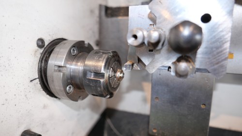
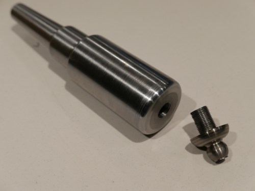
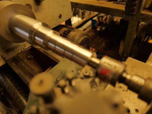
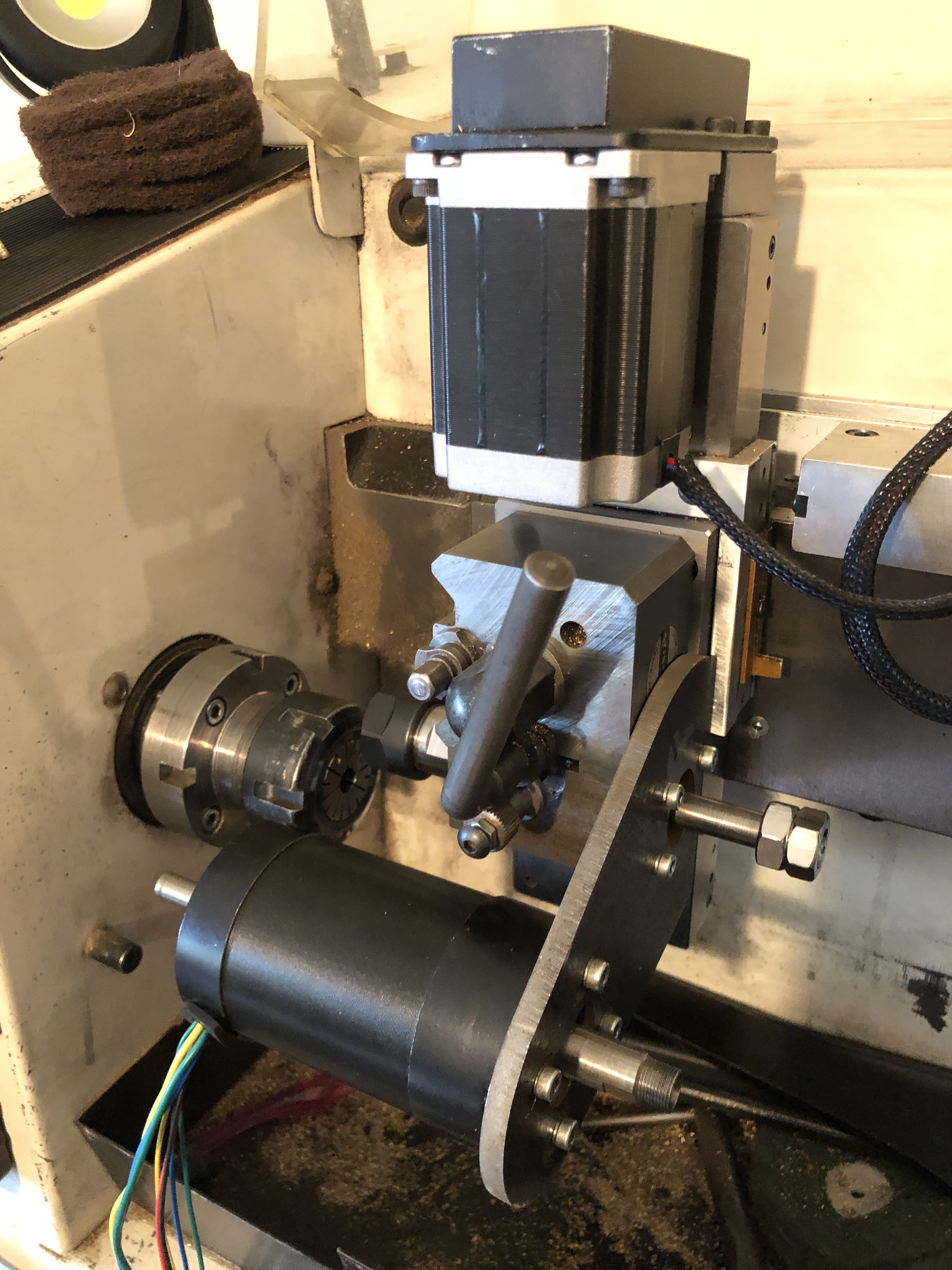
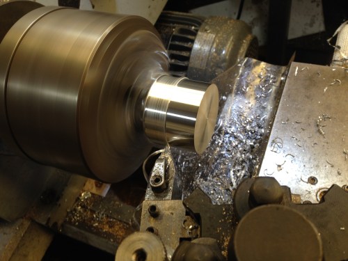
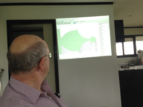
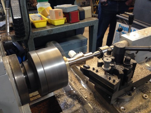
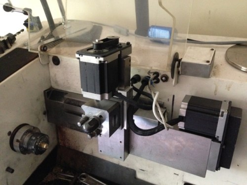
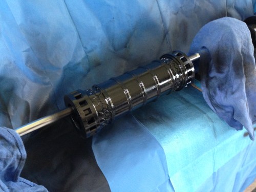
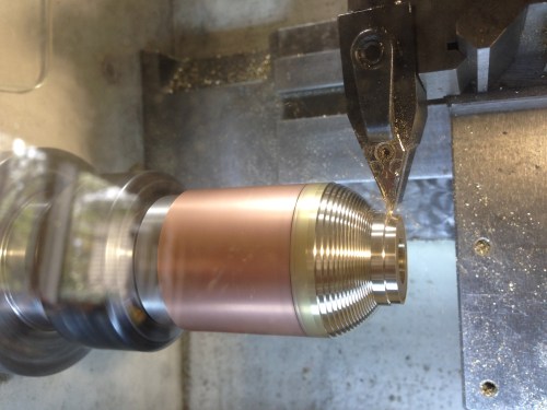
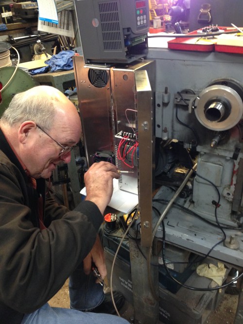
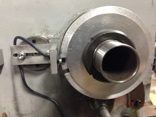
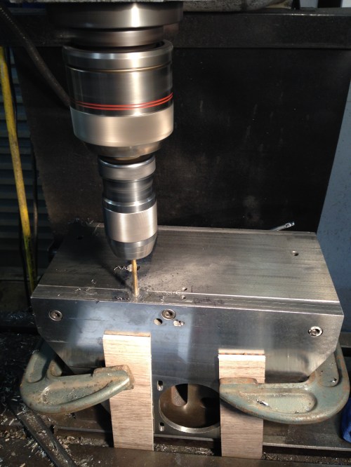
I thought of Robert more than once recently, when I was making an ER40 collet chuck for my CNC lathe.  The particular  collet chuck involved making a 2.25″ x 8tpi internal thread, a 50mm x 1.5mm external thread, and cutting an 8 degree internal taper.   Not too complicated you say.  I agree, but for the chuck to be useful, each step had to be extremely accurate.

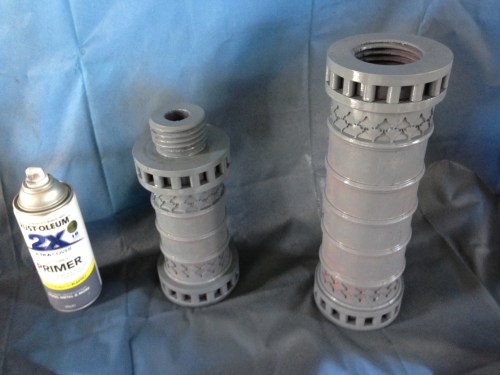
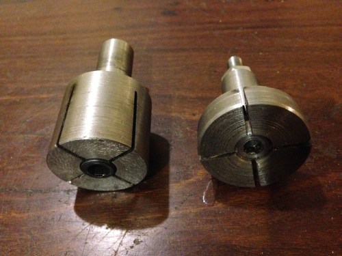
I made 4 successive collet chucks until one was adequately accurate.
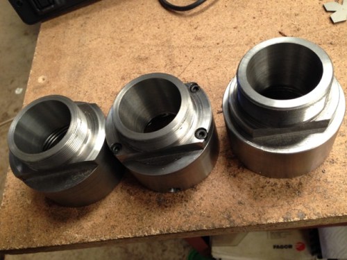
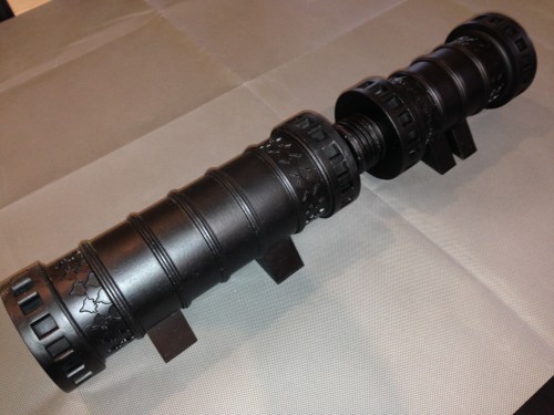
CNC lathe - 3.jpg

CHUCK 1, 2 and 3

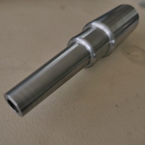
Chuck 1 actually went very well.   Nice tight spindle thread, taper good, and external thread just right.  But the chuck did not quite seat firmly.  Could it be that the spindle thread (the internal one) was not quite long enough?   So I cut a deep distal groove.    Wound out the carriage.   Oh shit!   Forgot to clear the spindle thread.   Totally destroyed it.   The chuck actually fitted the spindle quite nicely, but with only 10% of the thread remaining, it was useless.

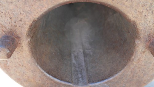
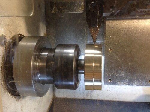
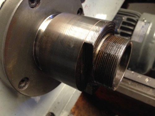
Chuck 2 was made in 2 pieces, on suggestion from Stuart T.  The idea being that if there was any inaccuracy in the lateral runout, the piece with the taper could be adjusted.  OK.   Sounded sensible.  Again all went well, but the spindle thread was not correct.  For some reason the thread cutter seemed to make a new path about half way through making the thread.   So the spindle thread was thinned  excessively.   But still tight.   So I made the tapered half, and joined it all together.  Fitted it to the lathe and measured the runout and taper.  All good.  Less than 0.01mm runout and perfectly parallel to 100mm from the chuck face.   But.   The next day I removed the chuck, replaced it, and did the runout measurements again.  I did not need a gauge.  I could see the wobble.  Chucked the chuck  into the rubbish bin.  That thinnned out spindle thread was hopeless.   But what caused the problem?  The thread was CNC cut, and it should have been perfect.

So chuck 3.   One piece again.    All seemed to go well, but again the big spindle thread was wrong.    Again there seemed to be 2 thread paths.

Then the penny dropped.   The spider made the web connection.   Robert got the throne and John saw the light.

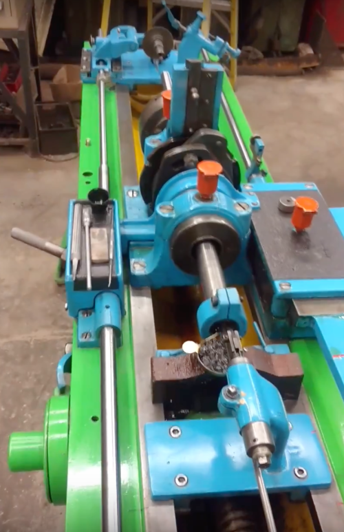
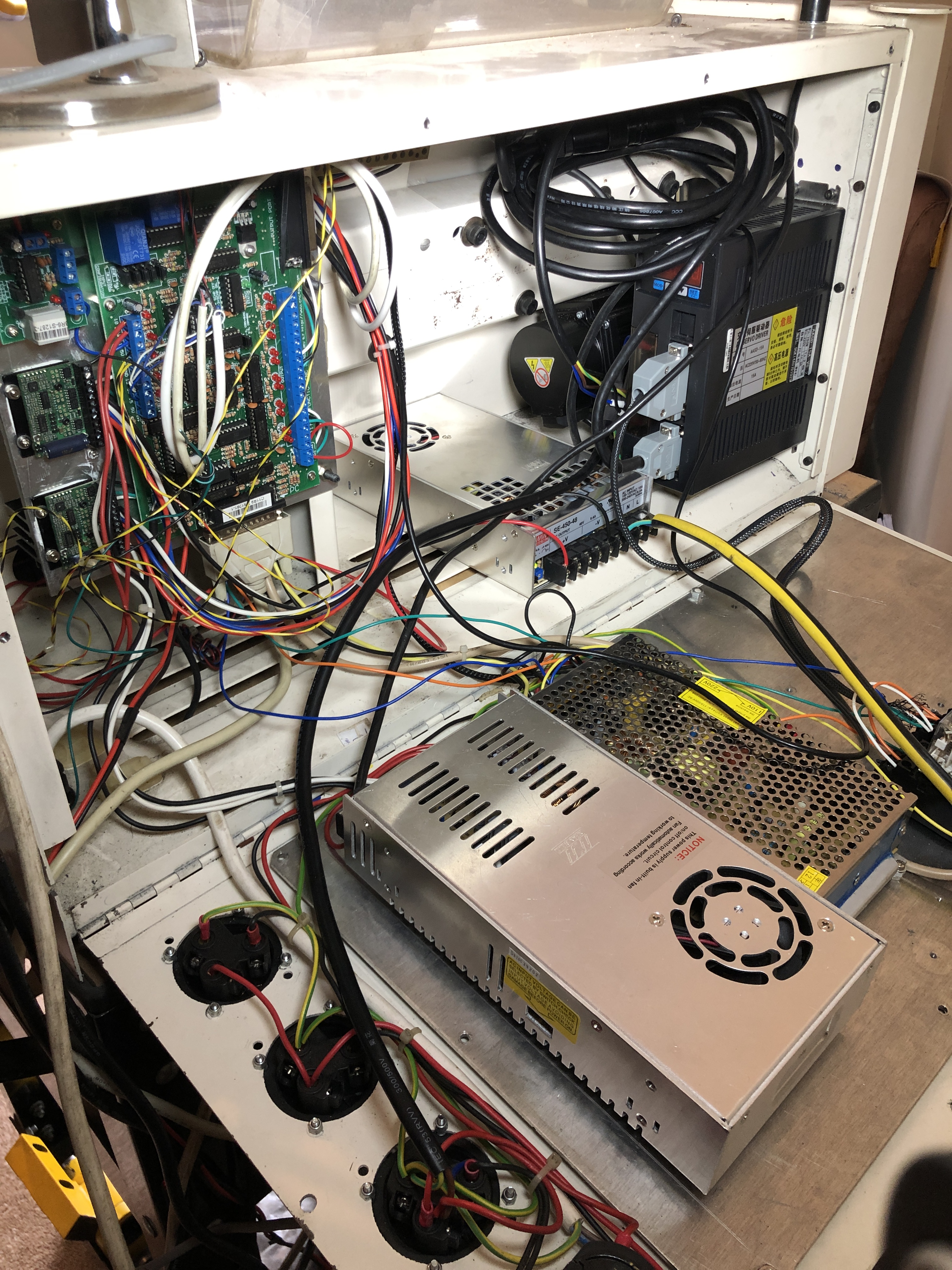
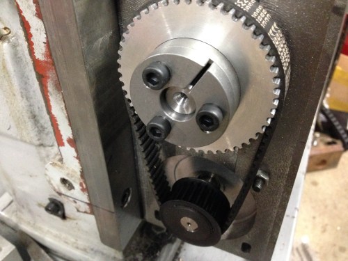
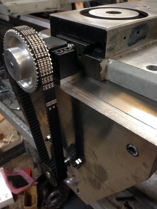
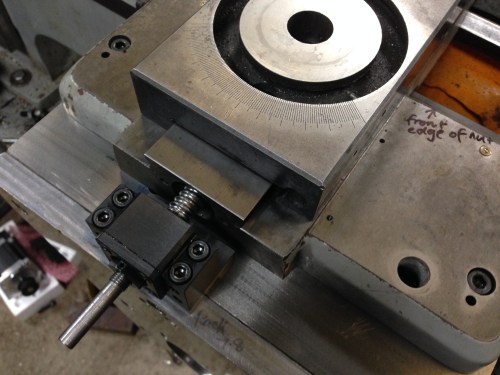
The tool post had moved slightly during the threading!  It had twisted a little, as a result of the T piece in the carriage slipping.  F**K    F**K  F**K!!!

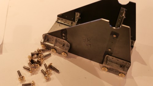
I replaced the T piece grub screws with more solid cap screws, and really tightened them.  Then made another chuck.    I must point out that each chuck was about 6-8 hours of machining, normally a very pleasant time.  But by this time, I felt like that  bloody spider in the cave.

cnc-lathe-5

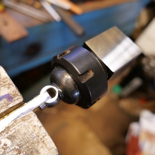
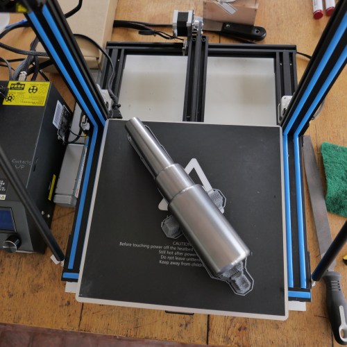
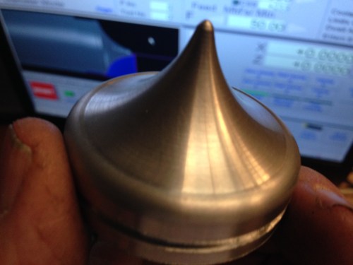
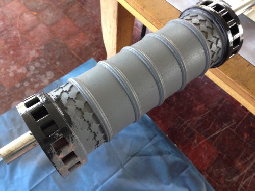
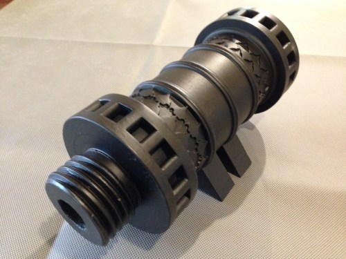
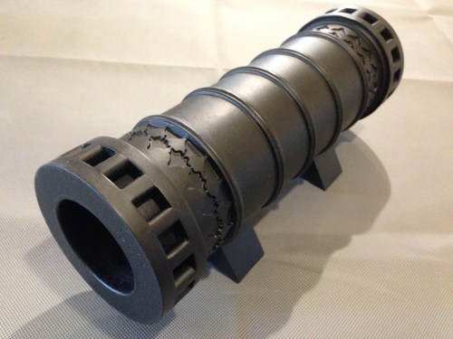
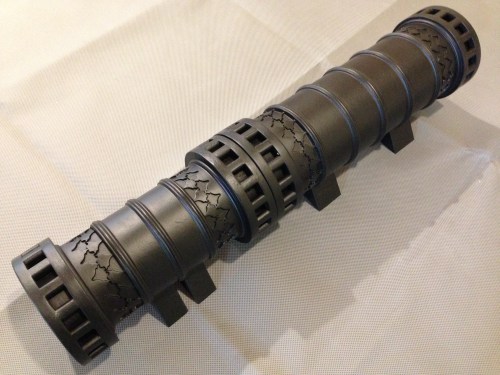
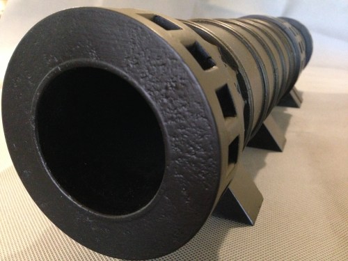
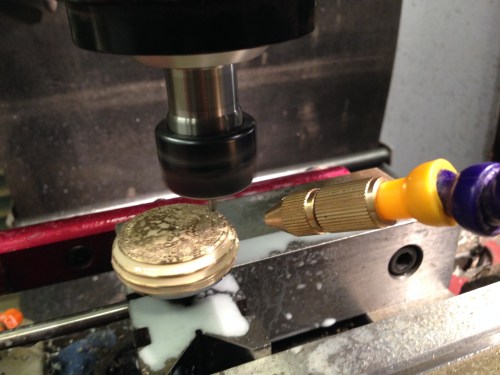
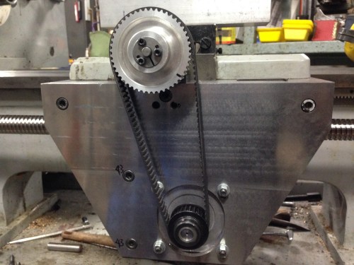
ER40 Chuck Number 4.

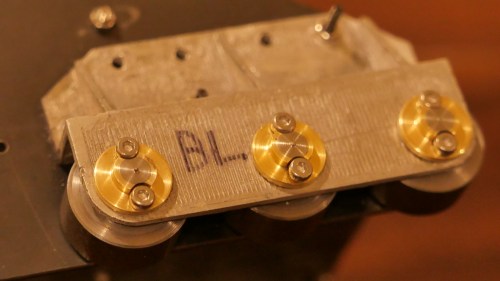
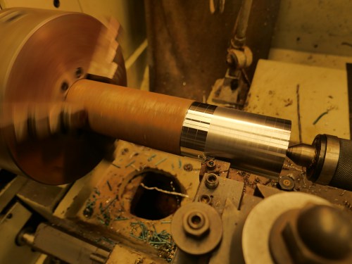
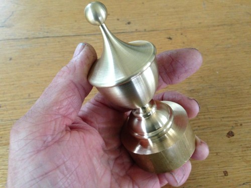
One advantage of making 4 chucks is that each one was made faster, and with more confidence.   This one was made in about 5-6 hours, including painting with selenium oxide to give it a black appearance.

It has a runout at the chuck face of 0 – 0.01mm (which might have been due to inaccuracy in the rod which was being measured), and a taper of 0.02mm at 50mm from the chuck face.  It feels nice and tight when being screwed on.   OK,  Success.   Eventually.

Next job, the throne of Scotland.

But obviously that slipping top slide on the CNC lathe has to follow chucks 1,2 and 3 into the rubbish bin.   It will be replaced by a fixed, immoveable tool post.

New Steppers for an old CNC Lathe

My Boxford TCL125 CNC lathe was missing steps in the cross slide, with resulting inaccurate work.  Obvious causes, like cutters not sharp, or gibs too tight were excluded.  Changes in the stepper motor settings maybe helped a bit, but not enough.

Stuart T suggested replacing the stepper motor, since the machine is a 1985 model, and the steppers look original, and therefore the 32 year old stepper permanent magnets are probably not as strong as they were originally.

We had changed the electronic controls in the lathe 3 or 4 years ago, so it would work with a Windows PC, and Mach3.  Mostly I use “Easylathe” for generating the G codes.

Stuart had a spare stepper motor in his junk box, and it was the correct size (Nema 23), but more powerful than original.  So I swapped it, and missing steps disappeared.  Hooray!  A minor problem was that Stuart’s stepper had shafts at both ends, and I was not comfortable about cutting off the unwanted shaft end, and I had decided to change the Z axis stepper also , so I ordered some new stepper motors.

A carton of 3 motors arrived a few days after placing the order.  They are made in China, and are nicely finished.  Each new motor had 4 wires, whereas the originals had 8 wires each, but reference to the wiring diagrams quickly determined the connections.  Total cost for the 3 motors was $AUD90, including postage, and now I have a spare.

A big advantage of the NEMA mounting system is that the motor mounting dimensions are fixed, so swapping motors is simple.  More powerful stepper motors are longer, but the dimensions are all available online, and can be checked before ordering.

cnc-lathe-1

The black and silver new stepper motors fitted to the Boxford TCL125.  One cover waiting to be reinstalled.

cnc-lathe-2

The old steppers on the right.   

A simple CNC turning test worked well, so I am hopeful that this problem is fixed.


Model Ottoman Bombard – Painting

I would have preferred that the title of this blog was “Finishing the Ottoman Bombard”, but I am still waiting for the vectors of the barrel mouth decorations and Arabic (?) writing, and the touch hole.

But I have at least painted the bombard, and the pictures follow.  You will notice that I have not attempted to reproduce the bronze or copper colours of the orginal in Fort Nelson.  Partly because I doubted my ability to make painting such variegated patterns realistic, and partly because the cannon would not have looked like that in its heyday of 1464.  It would probably have been either black, like most SBML cannons (smooth bore muzzle loading), or possibly gaudy golds and reds and blues like other medieval items.  So I painted it black.  I like it.  If I get evidence that it should be more colourful I can change it later.

IMG_4429.JPG

First coat – Primer.  Hmmm… interesting colour.

IMG_4434.JPG

Next coat – matt black brushed on, to fill the hairline wood cracks.  Incidentally, the (dirty) parquetry floor is also made from the red gum house stumps from which the cannon is made.

IMG_4447.JPG

final two coats –  matt black, from a spray can. 

IMG_4458.JPG

So there it is, finished except for the barrel mouth engraving, and the touch hole.  Now what to do with it…   SWMBO says it might be useful as an umbrella stand.

IMG_4460.JPG

The breech.  25mm diameter explosion chamber.  1:10 scale

IMG_4461.JPG

The barrel, 63mm bore.

IMG_4462.JPG

Assembled.  The model is 520mm long.

IMG_4464.JPG

It does need some decoration

turkish-bombard-plan

Modelling a Turkish Bombard -4 Decoration

The decoration around the barrel is formed by a repeating pattern, which when milled, very cleverly forms 2 identical patterns.  One is excavated and one is the original barrel surface.  You will see what I mean if you look at the pictures in the earlier blog, and the video below.

It took me an evening of experimenting on the computer to work out the system and draw it.

bombard-pattern3

Then I measured the diameters of the 2 gun components, calculated the circumference, (OK it is not rocket science.   3.142 times diameter), then working out the number of identical shapes which would fit around the 2 different diameters, at the same size and spacing.   Amazingly, it took 18 shapes to fit almost exactly around the barrel, and 16 of identical size almost exactly around the breech.  the angular spacing was 20 degrees and 22.5 degrees.

Then the shape was imported into V-Carve Pro, and G codes were generated.

My CNC mill does not have a 4th axis, so I used a dividing head to move the workpiece at the precise angles.  See the setup in the video.  That meant that the pattern was engraved into 16 and 18 flat surfaces, rather than a continuous cylinder as on the original.

It worked very well.  There were minor compromises due to the shapes being milled with a fine end mill but when you look at the pics I hope that you will agree that it is effective.

I calculated that the milling had to be at a maximum depth of 2mm in order to cope with the curvature, but if I do it again,  I would reduce the depth by 25%.

The first part of the video is a shot of CNC drilling.  Then the CNC routing of the repeating patterns.  Each angular setting of the pattern took 4 minutes to complete.  136 minutes altogether.  In reality, it took a whole day, most of which was spent doing the setups.


Bombard Model-3 turning the barrel

Another session or two, and this project is complete.

Now how do I make a cannon ball 62-63 mm diameter?  In wood will be ok?  Does not have to be granite.  I could make a mould and cast it in aluminium or lead, but stone would be authentic…..   thinking.

ps.  Re cannon balls.  I will cast them, in cement!   Now, how to make a mould.

Bombard Model -2. Big Thread

The breech and the barrel are joined with a very large thread.  On my 1:10 scale model it is 60mm diameter, and has a pitch of 6 mm.  These dimensions are measured off Internet photos of the original bombard, so they might not be faithfully accurate to the original bombard.  If anyone has accurate plans of the bombard I would be very interested to hear from them.

I experimented with various spindle speeds, feed rates, depth of cut, and finally decided that red gum wood is not the ideal material to be cutting a thread with sharp points.  However, at 200rpm, and taking 50 cuts to reach the full depth, and using a very sharp tool, the end result was OK.  I will fill the tearouts.

In order to make a functional join in the wooden cannon, I truncated the apex of the thread.  In the gunmetal version I will attempt a more faithful to the original, sharp look.

For some reason, the wood held together better during the internal thread cutting than the external.


The male thread was cut on my newly CNC converted lathe,  between centres, but the fixed steady on that lathe was just too small to hold the barrel, so the internal thread was cut on my bigger Chinese lathe.

Next I will bore the barrel to 63mm, then turn the exterior of the barrel.


Turkish Bombard 1:10 scale

Just for fun I will use my newly converted CNC lathe to make a 1:10 bombard.  The original was cast in 1464 and was thought to be a close copy of the bombards which Mehmet 2 (“the conqueror”) used to breach the walls of Constantinople in 1453.  There are several of these bombards still in existence, including one in UK, which was given to Queen Victoria by the then Turkish Sultan.

These bombards were last used, against the British, in 1807, when a British warship was holed with substantial loss of life.  Pretty amazing for a 340 year old weapon.

images

5.2 meters long, 1.060 meter diameter. 16.8 tonnes.

b281d1ba4455df20d7b832411bb00443

The large thread connected the halves.  Easier transportation, and casting.


images

Is this Turkish or Arabic?

images

Granite balls are 630mm diameter.


tembokkotakonstantinopel

A reconstruction of the walls of Constantinople, with moat.  Almost 1000 years old in 1453  

walls-of-constantinople

And as they are today.  Massive.  High.

29962555-Huge-siege-the-final-assault-and-fall-of-Constantinople.jpg

Huge siege cannon used in the final assault and fall of Constantinople in 1453. Diorama in Askeri Museum, Istanbul, Turkey.  The bombards were probably dug in, to manage the massive recoil, and concentrate the aim at a particular wall section.  There is a wooden structure built around the cannon in the background of this modern picture.  As far as I know there are no surviving  wooden structures like this.  Nor have I come across any old pictures, but if anyone knows of any I would be very interested.  The bombards took about 3 hours to cool, cleanout and reload.  

p1090990.jpg

My model will be about 520mm long.  I would like to make it from bronze, or gunmetal as in the original.  Any mistakes will be costly.

So I have decided to make a prototype in wood.  That will test my drawing, the machining procedure, and the final appearance.  Not to mention how the CNC lathe will handle the task.

I will use a very dense, tight grained Australian hardwood (red gum).  The wood was salvaged when my house stumps were replaced with concrete.  Some was used to make parquetry, and the rest was put aside for possible future use.  Such as this.

IMG_4313.JPG

About to cut off the below ground section of a 70 year old house stump.

IMG_4320.JPG

A 5hp metal lathe with a tungsten bit chomps through the hard dry wood.

IMG_4322.JPG

I turned 6 lengths before I found 2 that were satisfactory.  The rest had sap holes or splits.

I have used Ezilathe to generate the G codes.

to be continued….


A Matter of Scale

Before I get onto a brief reflection about scale, the photo below shows 2 cannon barrels.

The big one was what impelled me to converting a manual lathe into a CNC lathe.  That time consuming, costly, and ultimately very satisfying project, started because the CNC lathe which I used to turn the big barrel could only handle the job by doing it in two stages…. doing the breech first then the muzzle.  That was due to the big barrel being too long for the lathe, at 300mm (12″).

The small barrel was a test for the CNC converted lathe just finished, being the first complicated shape which I have made.   To save on material, I made it at exactly half the scale of the big one, ie 150mm long (6″).

IMG_4291.JPG

Comparing the two barrels reminded me, that if an object is twice as big as another, in all 3 dimensions (height, width, depth), it is 8 times as heavy.   And any projectile, and weight of black powder, would also be 8 times the weight.  But the wall thickness of the explosion chamber is only TWICE as thick.

My point is, that if scale is maintained, the smaller the cannon, steam engine, boiler, whatever…..  the less likely it is to explode.

Not that these cannons will ever be fired.  Just hypothetically.

CNC Lathe Conversion – 17

First Test Run

After some test runs without tool or material, I performed some measurements.

500mm movements along the Z axis were reproduced multiple times with a deviation of 0.00mm!  (the Z axis has a ground ball screw)

100mm movements along the X axis deviated 0.02mm.  (the X axis has a rolled ball screw).

I was delighted to note that the lathe is extremely quiet and smooth.  The only noise is some belt slap from the very old belts, and from the stepper motors.

The video below was taken from my iphone, while I was operating the lathe controls, so please excuse the erratic movements.

The steel is 27mm diameter.  750rpm, 50mm/min feeds.

And the guards will be made next step, without fail.

The G code was generated using Mach3 for these very simple shapes.  For more complex items I use Ezilathe.


The lathe is 600mm between centres.  38mm spindle bore.  Swing about 300mm.

Steam Engine Oilers

Knowing that I have an interest in CNC machining, Tom, from the Vintage Machinery Club in Geelong asked me to make a pair of oilers for a very old Wedlake and Dendy steam engine.  The engine is a large (to me anyway) stationary engine, which is run on steam several times each year.  The oilers for the cross slides were missing.

We searched the Internet for pictures of W&D steam engines, but could find no pictures or diagrams of the oilers.  So Tom sketched a design, and I drew a CAD diagram.  The dimensions were finally determined by the materials which I had available…  some 1.5″ brass rod and some 1.5″ copper tube.

This is the almost finished product.

IMG_4250.JPG

Just needs 1/4″ BSPT fittings and and oil wick tube so they can be fitted to the engine.

IMG_4222.JPG

The copper tube silver soldered to the brass cylinders (top), the brass blanks for the lids (bottom) and the mandrel to hold the assembly (bottom centre) during CNC turning and drilling.

IMG_4246.JPG

The mandrel to hold the body (left) and the mandrel for the lid (right).  The cap screw head and hole in the mandrel have a 2 degree taper.  The slits were cut with a 1mm thick friction blade.

IMG_4243.JPG

Rough turning the base.

IMG_4231.JPG

Turning the lid.  The mandrel is held in an ER32 collet chuck

IMG_4245.JPG

Engraving the lid.  Using a mister for cooling and lubrication.  16000rpm, 200mm/min, 90 degree TC engraving cutter.

IMG_4251.JPG

The oilers work by wicking the oil from the reservoir into a tube which drains through the base onto the engine slide.  When the wick tubes are fitted the oilers can be fitted to the engine.

IMG_3196.JPG

The 1865 Wedlake and Dendy

IMG_3195.JPG

1865

My lathe is a Boxford TCL125, using Mach3.  The G code is generated using Ezilathe.

Below is a link to an oil cup from “USS Monitor”, of American civil war fame.   One of the first ironclads, powered only by steam.

http://www.marinersmuseum.org/blog/2010/04/one-oil-cup-down/

(ps. The  lathe which I was converting to CNC was the subject of previous posts and is now working, but needs some guards fitted and a bit of fine tuning.)

CNC Lathe conversion -16

The wiring of the lathe is complete.  (Except for limit switches.  They can be added at any time).

Mach 3 is configured.  The wireless hand control is installed and working.  Ezilathe installed and waiting for input.

Some covers to be made.

IMG_4154

Hook ups in progress.  That’s the faulty VSD on top of the electronics enclosure.  The CNC engineer lost his hair trying to figure out the problem.

Still some testing and fine tuning required.

But nothing much will happen in the workshop for the next  3 weeks.


CNC lathe conversion -15

Another couple of advances in the conversion.  Today I installed the lead screw cover and the cable protector to the cross slide stepper motor.

The cable protector was easy and straightforward. It flexes in one direction only, and is fixed at the ends after the cable is threaded through it.  The length is adjusted by adding or removing links.  It was placed so that coolant liquid will drain out of it, and to minimise the accumulation of swarf.   The cables themselves have a thick covering and are well protected.  The link protector will not kink, further protecting the cable.

It was cheap.  About $AUD20 for 2 meters, posted from China.  I used about 1.1m.

cnc lathe - 2.jpg

Showing the stepper motor cable protector, and the lead screw protector (one half of it.  The other half is on the other side of the carriage.)

The lead screw protector was another story.  It is a spring steel coil, about 50mm wide, and as it is compressed the coils fit inside each other.  I made a big mistake in allowing it to spring open before I had installed it (there were no instructions).  It immediately opened to a length of over a meter, in coils about 50-60mm diameter.   No big deal, I thought.  I will just compress it back to its original configuration.    Big mistake.

It was what I imagine coiling a live, oily, biting, boa constrictor would be like.  (OK, boas constrict rather than bite.  How about an anaconda, or a big eel.)

I fought it for about an hour.  And eventually succeeded.  Minus a few bits of my skin.

So I did not allow the protectors to expand again until after I had them on the lead screw.

This is what they look like.   Pretty cool IMO.  They just expanded into position when I removed the restraining clips.

cnc lathe - 3.jpg

The lead screw stepper motor and protector.  The Estop box above will get some ends to exclude swarf.

It was not cheap.  The best price that I could find was from South Korea.  $AUD200 inc postage.  But it is excellent Japanese quality.

The wiring is happening, but the variable speed drive seems to be dead.  It has been sitting unused on a shelf for 2 years, so no point asking about warranty.  Took it apart to check for broken wires, fuses, burnt out components etc, but nothing visible.  Will order another one.  About $AUD200.  An unexpected expense.


CNC lathe conversion -14

These lathe CNC conversion posts are probably becoming a bit tiresome, but just in case there is someone out there who is interested, I will continue until the job is finished.

The latest was to make and install a spindle speed (and position – thanks David M) sensor.  It consists of a disk with a slot cut in the periphery, attached to the main spindle.  And an opto-electronic sensor which is connected to its own electronic board, thence to the breakout board and VSD.

cnc lathe - 1.jpg

The disc with the slot at 8:30 and the sensor at 9:00.  I must have chosen the wrong cutter or turning speed for that disc aluminium…  looks a bit rough.  (note added 13/7    Stuart T says that I should have used coolant-lubricant).

cnc lathe - 4.jpg

View from above.  Any clearer?   That gear is now superfluous except as a spacer.

So there is one electronic impulse per spindle revolution.  That is enough to measure the RPM’s.   Essential for cutting threads.

The beauty of this system is that there is no gear selection or changing, and ANY thread pitch can be selected…  metric, imperial, BA  etc…  any odd ball thread that your heart desires.

cnc lathe - 2

cnc lathe - 3

The HTD (high torque drive, I am informed by many readers) pulleys and belts and taper lock fittings.  Unfortunately I could not find a taper lock to fit the small pulleys, so when it is all finally, definitely, absolutely, correctly,  positioned, I will Loctite them in position.  Protective covers yet to be made.  I quite like to see the mechanicals in action, so I am intending to make the covers from clear polycarbonate.(Lexan) .

CNC Lathe conversion -13

IMG_4125

Adjusting the lead screw.

The 48 tooth HTD pulley has been installed using a taper lock.

Then some time was spent adjusting the parallelism of the lead screw.  That requires quite a few movements of the carriage along the 600mm thread.  Each 360 degree turn of the lead screw advances the carriage 6mm, so you can understand that I became a bit impatient with all of the repetitive hand actions to move the carriage from one end to the other.

So this was a solution to that issue.  That HTD belt is the one that was too long, so I was happy to find a use for it.    The variable speed battery drill shot the carriage end to end in a couple of seconds.

All is now adjusted parallel.

A few more little installation issues, then for the wiring.

CNC Lathe conversion -12

Today I fitted the lead screw.

No big deal, I sense that you are thinking.  After all, the ends are machined, the bearings fitted, and all waits in readiness.

True, but there is a strict sequence of events.  And since it has been 3 or more weeks since it has been together, I had to rediscover the sequence, by trial and error.  And each bit of the fitting is very heavy, very delicate, very tricky.  So it took me several hours to get to the  final photo in this blog.

But first a view of the inside of the newly machined apron.

IMG_4122.jpg


IMG_4123.JPG

The lead screw fitted.  The cross slide screw is also fitted.  Note the red E Stop panic button fitted to the left.    Next job is to fit a support bearing at the right hand end of the screw.  Then to check and adjust parallelism of the screws.  A rough check showed that they are within 0.25mm

CNC Lathe conversion -11. Ball screw machining.

Hooray!

Today I collected the lead screw after the ends were machined by Statewide Linear Bearings.

I decided to drive the 100km each way to pick it up, in preference to using a courier.  I wanted to ensure that all of the small bits were there, and also just to make sure it was handled properly.  Mostly freeway, listening to Dan Carlin on the Persian-Greek wars, so it was a pleasant way  to have 3-4 hours to myself.  (If you do not know about Dan Carlin, Google him and download an episode.  If history at school had been like this, we would all be history addicts.)

IMG_4117.JPG

This is the lead screw, ends machined, and support bearings fitted.  1100mm long. 28mm dia

All good, except that the nut was back to front.  That nut is pre-tensioned, which means that the 2 halves are separated by a precisely machined washer.  I was nervous about removing it and replacing it the correct way around.  However I had previously asked the ball screw expert about that aspect, so armed with the technique I made up a sleeve of the correct size, removed the nut and replaced it.   No balls fell out.   So all good!  The above picture shows the nut in its correct position.

IMG_4118.JPG

The nut.  Looks expensive?  Is expensive.  And beautiful.

IMG_4120.JPG

The machined driven end.   $AUD250 machining there.  But it is perfectly done.

IMG_4119.JPG

And with the support bearing installed.  A pulley for the HTD belt goes on the distal bit of shaft.


IMG_4112

The CNC lathe has 3 belts. There is a V belt from the 3 phase motor to the main lathe spindle.  Although I changed the motor and the pulleys, the old belt fitted, which was good.  No hassle. But the stepper motors driving the lead screw and cross slide screw, and their pulleys were all […]

CNC Lathe conversion – 9

The CNC lathe conversion has been happening, despite no posts on the blog.

I have mounted the electronics enclosure, and mounted the various components inside.  No wiring yet.

IMG_4110

This stainless steel tool box is the electronics enclosure.  It fits the space quite nicely, and is adequately big.  The back gear cover to the right will be retained, although the back gears have been discarded.  The main switch and emergency stop will be mounted somewhere on this cover.

IMG_4109

The Variable speed drive (VSD) sits on top.  That will control the spindle speed.  The transformers, stepper motor drives, and Breakout board (the heart of the system) are positioned inside.  Plus cooling fan and filters.  Ready for wiring.

IMG_4107

Drilling the apron to attach the cross slide ball screw bearing.  One chance only at this one, so the setting up took a couple of hours.  The apron is clamped to a large angle bracket on the milling table.   M6 threading followed.

IMG_4108

The end result.  The bearing as attached to the apron and the ball screw is in place.  I machined the end of this ball screw to fit the bearing, cut a thread (M10x1), and machined the end to accept the pulley.  All good.  There is 0.25mm adjustment available if required, but it all seems pretty correct.  The bearing sits on a carefully machined block which is 7.85mm thick.   Still waiting the lead screw machining.(!!)

NOT MUCH GOING ON TODAY

IMG_4092

This is my workbench after I had almost finished tidying it.  Really.  


Then I thought about machining the ends of the cross slide ball screw.

IMG_4095

So I mounted the collet chuck and checked the runout.   0 to o.01mm.  Then I did a test cut in the ball screw.   Hard hard hard.  But it did cut.  Then I chickened out and decided to finish it another day.

So, looking around the workshop for something else to do, I decided to pretty up the new CNC lathe apron.

IMG_4087

Before (milled surface).

IMG_4093

During


And I forgot to take a photo of the after, but it did look nice and smooth and shiny (look at the mirror finish behind the wheel).

Being retired is great!

CNC Lathe Conversion – 8

Continuing the installation of the ball screws, and stepper motors.

I have completely removed the digital read out module and glass slides, and they will not be reinstalled.  Not sure what I will do with them.   They are only a year or two old, and in good condition.  I will probably put them on Ebay.  Same with the old gearbox, carriage apron, and electric controls.

Here are some pics of the plates and blocks which support the ball screws and steppers.

IMG_4089.JPG

This is the steel plate at the headstock end, bolted to the bed.  And the block with the holes is cast iron 42mm thick, to support the leadscrew and leadscrew stepper motor.  It was machined out of an old piece of machinery, hence some unintended holes.   Being cast iron it was fairly easy to machine, but incredibly dirty. Turned everything in the workshop black, including me.  (whoops.   Unintended not PC)

IMG_4087.JPG

This is the block which replaces the gears and controls of the apron under the carriage.  The thick block is cast iron, and the stepper motor support is 20mm thick steel.  Very heavy.

IMG_4086.JPG

This plate is hidden under the carriage.  It secures the lead screw nut.

IMG_4085.JPG

The slot in the carriage had to be widened and deepened a bit, in order to accomodate the slightly fatter and taller cross slide nut.  See the next photo to see the setup for milling the hole through the carriage.

IMG_4084.JPG

A rather confusing photo.  The carriage is clamped to a large angle plate on the mill, and I am enlarging the hole which accommodates the cross slide ball screw.  It was at the limit of what my mill could manage.  An intermittent cut, with a lot of tool stick out.   Not the best way of doing the job, but it worked OK.

IMG_4088.JPG

Plastic covers attached to the stepper motors, and toothed belt pulleys fitted.

IMG_4075.JPG

Checking the centres between the pulleys, using 2 wooden wedges to push the pulleys apart.

IMG_4083.JPG

The underside of the carriage.  The hole and channel at the left side of the picture was machined to accept the larger cross slide screw

So you can see that I have been busy since the last post.

At present the lead screw is at Linear Bearings in Melbourne, having the ends machined to accept the driving pulley, and support bearings.  I did consider doing this machining myself, but decided to leave it to the professionals because of the high cost of the item and the hardness of the material.

CNC Lathe conversion-7

I am still waiting for the replacement ball nut for the lathe cross slide to arrive.

Meanwhile, I have been busy machining the supports for the lead screw.

IMG_4054.JPG

Drilling the holes for the support bolts for the lead screw nut

IMG_4055.JPG

And gradually drilling the hole to 49mm!

IMG_4059.JPG

That is a 49mm drill!  First time that I have used it!  Thank goodness for the  FS Wizard app, to give me some idea about feeds and speeds.  Following this I used a boring head to enlarge the hole to 55mm.

IMG_4063.JPG

Gradually enlarged the hole in 20mm steel to 55mm diameter.  and here is the lead ball screw, sitting roughly in its proper position.

IMG_4064.JPG

So this is where I am at.  The lead ball screw is sitting approximately in its correct position.  Considerable adjustment required.  And I am yet to turn the ball screw ends to their correct dimensions.

CNC lathe conversion-6. EBay problem

My first hitch occurred today.

I was very excited to receive the nut for the cross slide ball screw.  If you have been following these posts you might recall that the ground ball screw for the cross slide came from Taiwan, and arrived in 3 days.  But I had to order the nut from a seller in USA.  The nut was advertised as new old stock, but with no packaging.  That was OK, but the postage cost for such a tiny item was ferocious.

It was the last item to arrive from overseas.   However when I looked at it, it was obviously NOT new.

IMG_4043.JPG

The cap screws holding the ball recirculating tube were different from each other, and the washers underneath were too big for the screws.  Obviously not the way that TNK made it.  Somebody has had the nut apart.  And the ball retaining tube was very scratched  and loose.  Again, not TNK standard.

But no biggie.  If it works — fine.

So I turned up a retaining tube to remove the previous nut from the ballscrew, and it came off without any drama.

cnc lathe - 1

But when I tried to fit the “new” nut, it just would not go on.  Tried reversing the direction.  No go.  Bugger bugger.

Somebody has altered or changed the “new” nut.  Maybe installed balls which are too big, or maybe damaged the entry thread.  I do not know.

What to do.  I have been waiting 2 weeks for this to arrive.

First, Ebay email to the seller.  See what the response is.  Ask for a refund.  The postage was almost as expensive as the nut. If unsatisfactory response, they will get the worst Ebay feedback ever.

There is one other seller of these nuts on Ebay, also in USA, and 50% more expensive, and the postage is also 50% more expensive. (how DOES ebay come up with the postage charges.  It seems more related to the cost of the item rather than the weight-size etc.)  But the nuts are in original packaging.  And I want to get going with this, so fuck it.  Pay up and get it.

I will report in a later post.  (if the bad language in this post seems to reflect my state of mind, well, yes it does.)


PS.  Next day.  After sending photos of the issue, the seller accepted responsibility, and I am getting a full refund.  That restores my faith in Ebay/Paypal.   I hope that the next one is in better condition, and comes a bit more quickly.  Sorry for the bad language.