
CNC lathe conversion -14
by John
These lathe CNC conversion posts are probably becoming a bit tiresome, but just in case there is someone out there who is interested, I will continue until the job is finished.
The latest was to make and install a spindle speed (and position – thanks David M) sensor. It consists of a disk with a slot cut in the periphery, attached to the main spindle. And an opto-electronic sensor which is connected to its own electronic board, thence to the breakout board and VSD.
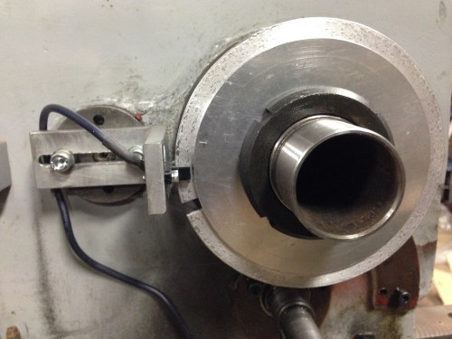
The disc with the slot at 8:30 and the sensor at 9:00. I must have chosen the wrong cutter or turning speed for that disc aluminium… looks a bit rough. (note added 13/7 Stuart T says that I should have used coolant-lubricant).
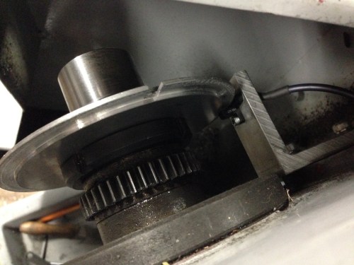
View from above. Any clearer? That gear is now superfluous except as a spacer.
So there is one electronic impulse per spindle revolution. That is enough to measure the RPM’s. Essential for cutting threads.
The beauty of this system is that there is no gear selection or changing, and ANY thread pitch can be selected… metric, imperial, BA etc… any odd ball thread that your heart desires.
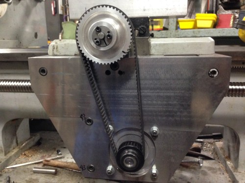
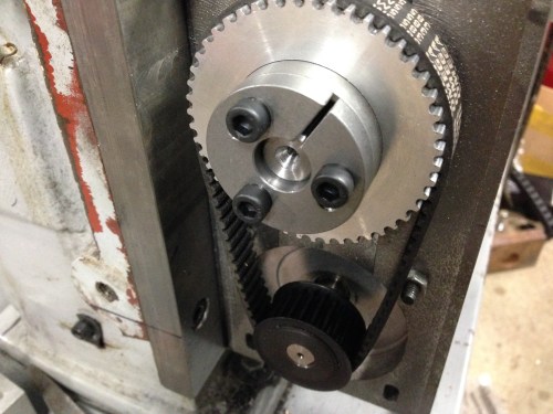
The HTD (high torque drive, I am informed by many readers) pulleys and belts and taper lock fittings. Unfortunately I could not find a taper lock to fit the small pulleys, so when it is all finally, definitely, absolutely, correctly, positioned, I will Loctite them in position. Protective covers yet to be made. I quite like to see the mechanicals in action, so I am intending to make the covers from clear polycarbonate.(Lexan) .

I don’t know about anyone else, but I am finding this post very interesting.
Peter W Viggers 0429 184 092
LikeLike
Thanks Bro.
LikeLike
You are such a perfectionist! Of course, that is what is needed to do a proper CNC lathe conversion, much less machine anything.
I’ve learned so much from following your blog. I like the proposal of a clear polycarbonate cover on the HTD so you can see the gears and belt move.
Can’t wait to see what you make when it’s done!
LikeLike
Thanks Richard. I am pleased that I am not the only odd ball.
LikeLike
Sorry, John,
The one slot disc is used to synchronise the drop in point for thread cutting, not for speed sensing ie position sensing.
When the saddle moves back to the start point for a second cut the relationship between the angular position of the work and the cutting tool is lost.
The CNC controller will have the saddle wait at a pre-defined position until the work rotates to the right angular position before a second or further cut is started. The time to start the cut is indicated by the single slot disc.
I would expect that threading will start when the signal from the optointerrupter changes from high to low or low to high, depending on how the CNC controller is set up. (Edge triggered) As an aside this why that, within reason, the slot width doesn’t matter.
The effect is similar to using the chasing dial on a conventional lathe to select the start point for threading.
David M
LikeLike
Hi David and thank you for your comments which are obviously correct about the threading drop in point. I will be controlling the lathe with Mach 3, and I think that I am correct in saying that the RPM displayed on Mach 3 comes from the slotted disk – sensor.
John
LikeLike
Hi John,
A speed display is a convenience from the single slot disc. It could be just as easily available from an eight or sixteen (or more) slot wheel.
A CNC lathe doesn’t need the single slot disc if you are-
1/ not doing threading.
2/ not needing the derived speed from the sensor for closed loop speed control of the variable speed headstock drive. In this case more slots might give better control at the expense of a higher pulse rate. Especially with sluggish optocouplers.
Essentially the single slot disc provides an angular reference so that threading begins at the same point for each pass of the cutting tool.
David
LikeLike
I think it is very interesting.
john f
LikeLike
Thanks John. I wasn’t getting any feedback, so I was considering options. John
LikeLike
Hi john,
In the middle of my own CNC lathe project. Having yours so well documented has helped me quiet alot thank you.
Where did you get the taper lock pulleys from?
Cheers,
Josh
LikeLike
Hi Josh and thanks for the nice feedback. The taper locks came from Naismith Engineering in Melbourne. They were very helpful and have an excellent mail order service. John.
LikeLike