machines which I have made, am making, or intend to make, and some other stuff. If you find this site interesting, please leave a comment. I read every comment and respond to most. n.b. There is a list of my first 800 posts in my post of 17 June 2021, titled "800 Posts"
Following on from the previous post, I was not happy about the requirement of changing the work holding for every deadeye, when I intend to make several hundred of them. The problem is the need to drill holes in one axis (the Z axis) and then to turn or cut the outside circumference and to turn a groove into that outside circumference. Plus rounding over all of the sharp edges. All in a piece of wood which is smaller than a flattened pea.
So, I consulted my expert CNC friend Stuart, on the suggestion of Brendan, another GSMEE member, who remembered Stuart’s brass handwheels which he made on his Boxford and churned out multiple copies.
“Why don’t you use the Boxford CNC lathe?” Stuart said. “Ideal for such small objects”. “And use the milling attachment for drilling the face holes”. (without changing anything except the tool)
He came up with that solution in about 10 seconds, after I had explained what a deadeye is.
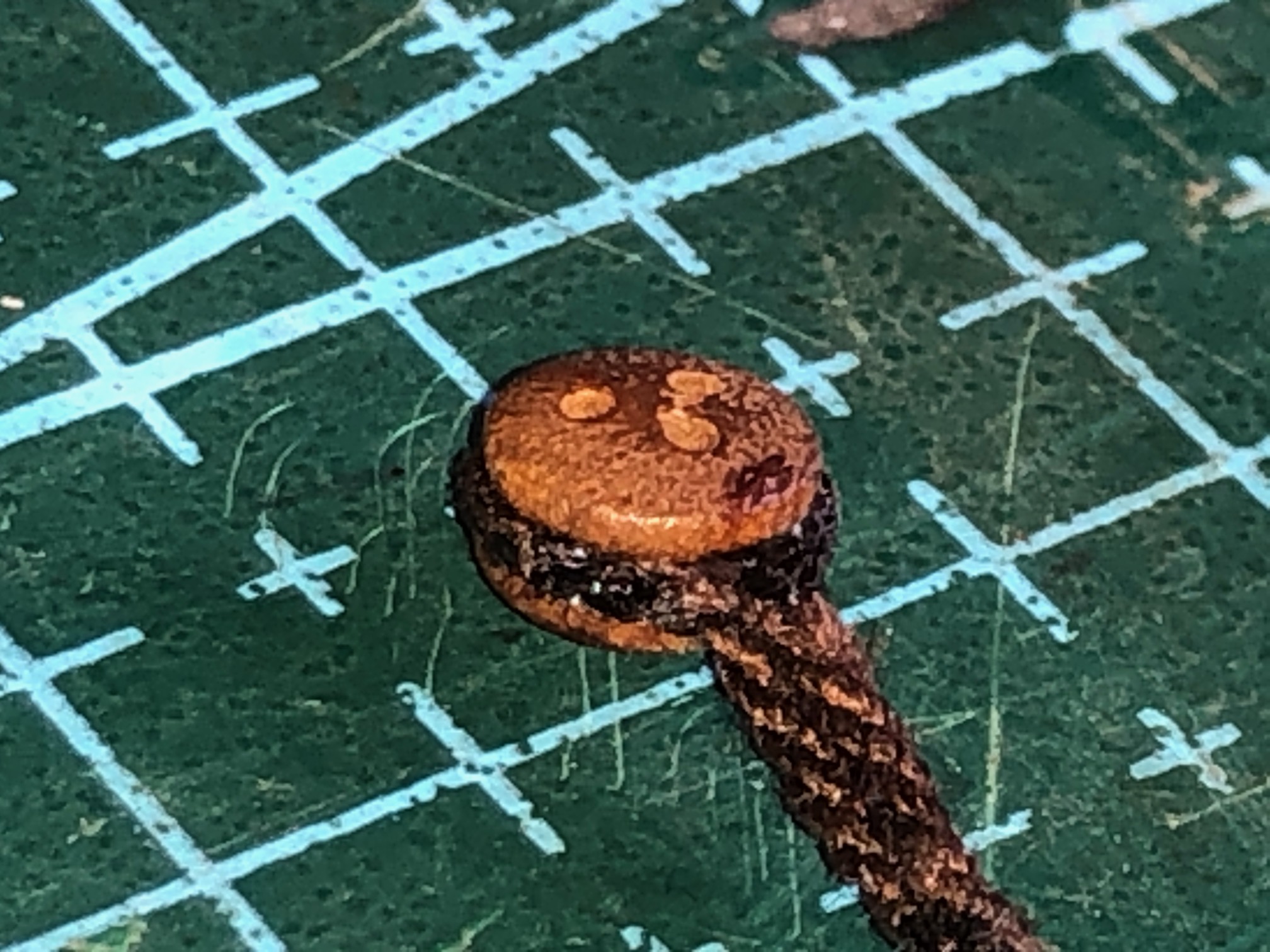
That model deadeye is 5mm diameter, 3.2mm thick, and has 3 face holes about 0.8mm diameter
I had been thinking about solutions for several days, and spent a whole half day making the annular cutter which I described yesterday. Using Stuart’s solution, the annular cutter wont be necessary. Oh well. It will come in handy one day. Maybe.
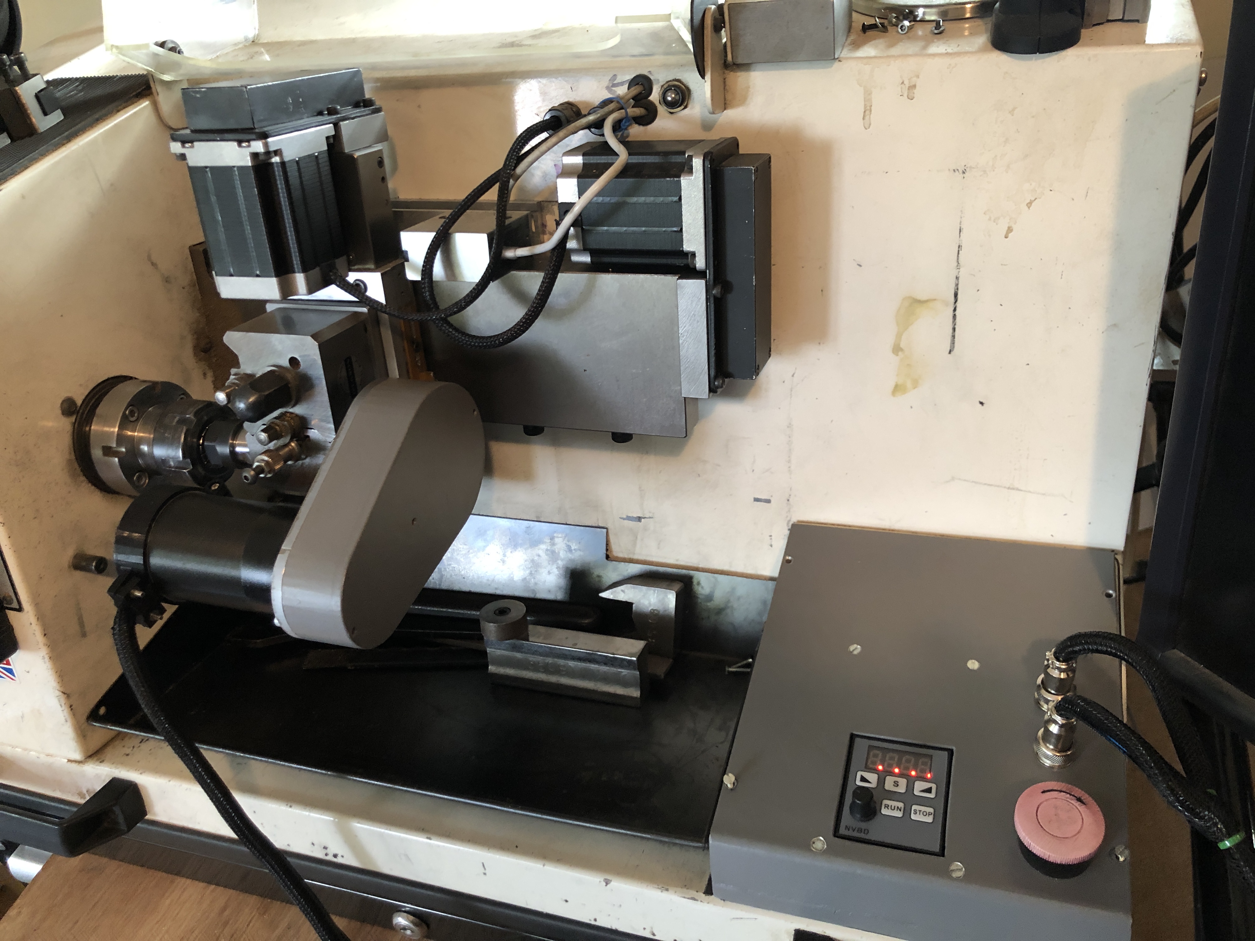
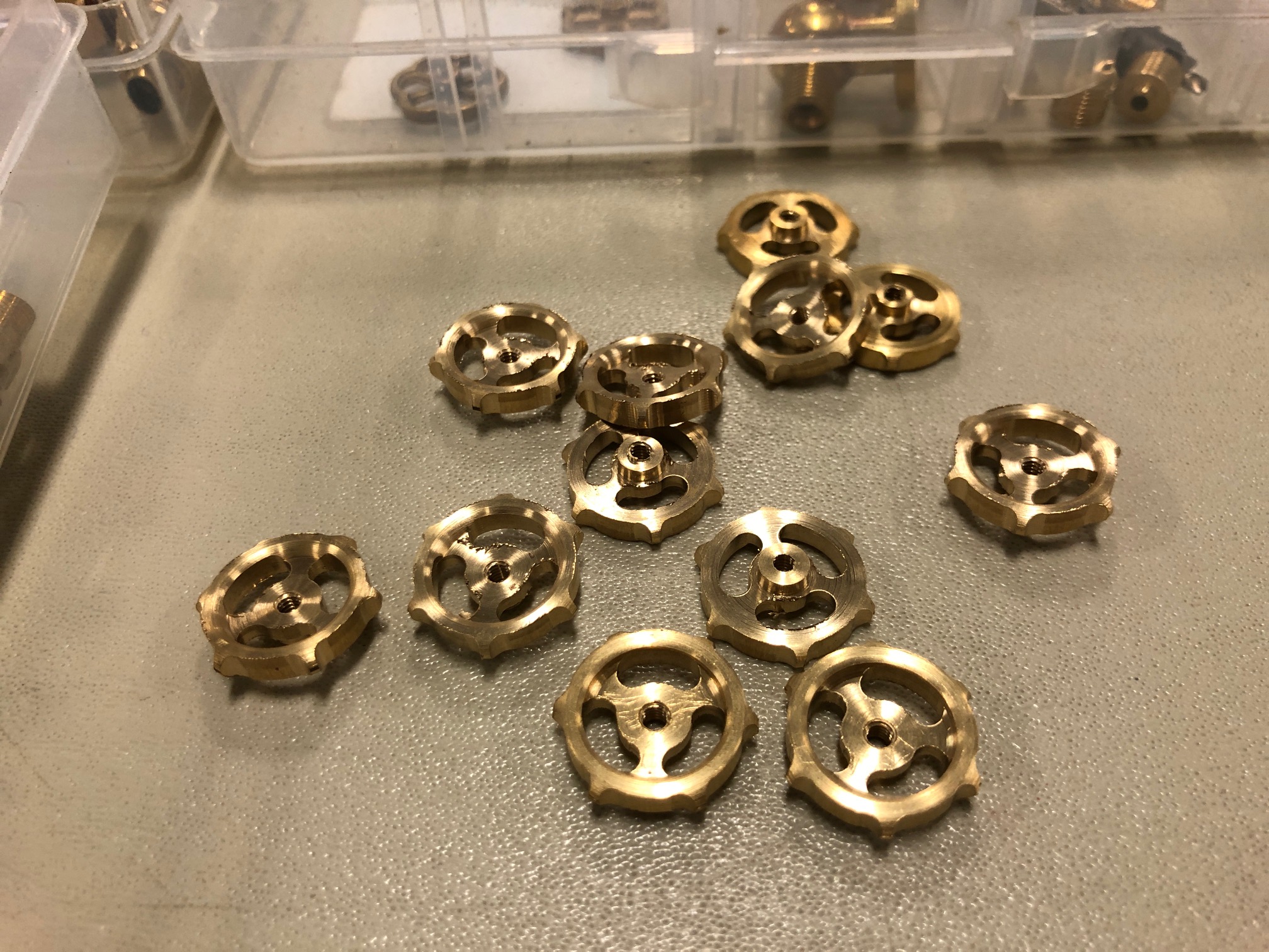
This is my Boxford TCL127 CNC lathe, and shows the CNC milling attachment on the tool post. So it has X,Y and Z axes, and a motorised CNC rotary axis, which has an independent speed control, and can be instructed to go to any angular position. The attachment was designed by my brilliant friend Stuart Tankard. Made by me. It is small, but IDEAL for deadeyes. Definitely the way to go.Some tiny handwheels made by Stuart on his Boxford CNC lathe with milling attachment. A bit bigger than my deadeyes, but more complex. The deadeyes should be deadeasy in comparison.
A few of my first degree relatives have ADD or ADHD. I have never been officially diagnosed as such, but I know that I have similar characteristics. Like jumping from one project to another. Or suddenly shifting topics of conversation, sometimes to the discomfiture of to whomsoever I am talking. (I will not end a sentence with a preposition. It is something up with which I will not put.- apology to Winston Churchill, I think).
The latest examples are the ropewalk, the CNC mill, and the CNC seizing serving machine. My readers must wonder “where to today?”
Well, I decided that I need more deadeyes for my model Constitution.
The little round things with the forlorn faces are deadeyes. I suppose that they are forlorn because they are dead. These deadeyes are walnut and came with the Mamoli kit. They must have been hand drilled, because many of them have lopsided and or asymmetric faces. I find them disturbing, so I purchased another 100 of them, of which about half suffer similar disfigurement. (up with which I will not put!)
So, I have ADDishly shifted my thoughts from seizing serving and ropemaking, to making deadeyes.
I searched YouTube, and the model ship building sites, and my model ship building books for information on the subject. There was much advice on how to make model deadeyes, laboriously, slowly, and not very satisfactorily, IMO.
I want to use my CNC mill and/or CNC lathe to churn out hundreds of them, at least SEMI automatically, if not TOTALLY automatically.
My thoughts to date are that……. 1. A block of wood (walnut or similar) is machined to size to make say 100 deadeyes (or maybe 500.) 2. The holes for all of the deadeyes (that would be 300 holes) are CNC drilled. (I reckon that would take 3-5 seconds per hole, say 5″ altogether, estimated.) 3. The round edge of the deadeyes is cut with an annular cutter (more of that later), say 2-3″ plus time for tool change. 4. Somehow, the circumferential groove is machined. Probably in a lathe, and probably one at a time. Much slower, maybe a minute for each deadeye. Workholding is the main issue, but I have thoughts on that subject. 5. Then the edges are rounded. ahah! I have an easy solution for that. Maybe another 10″. Watch this space. No announcement until the idea is tested.
SO that is the plan. Yes, I should just pay someone else. But, I have set the idea in motion, so I will continue.
For several days I have trawled Ebay, Temu, Banggood, and my local wood workers retailer looking for an annular cutter which will leave a 5mm diameter center. The smallest I could find had a 0.25″/6.35mm center. Too big. Plus, if my idea works, I will want even smaller annular cutters.
So, I made one.
Firstly I found some 8mm diameter hardened steel rod about 100mm long, and I drilled a 5mm hole through it lengthways. It was slow drilling, using a cobalt drill, and plenty of lubricant, but it worked. Maybe it was just case hardened.
The gentle giant German, Stefan Gotteswinter, recently posted a YT video about making a 1.6mm diameter annular cutter so I just followed his suggestions. Incidentally, anyone who is interested in expert precision machining should subscribe to Stefan. His English is better than most native English speakers. And his work is sublime.
Then I hardened and tempered the ends of the tube. Heated cherry red. OK, maybe a bit overheated. Then quenched in water. Then heated to straw colour and allowed to cool slowly. It passed the file test.Then ground the 4 teeth, as described by Stefan Gotteswinter, except that my T&C grinder is a bit more primitive. I deliberately made deep gullets. And touched up the cutting edges with a fine diamond file.
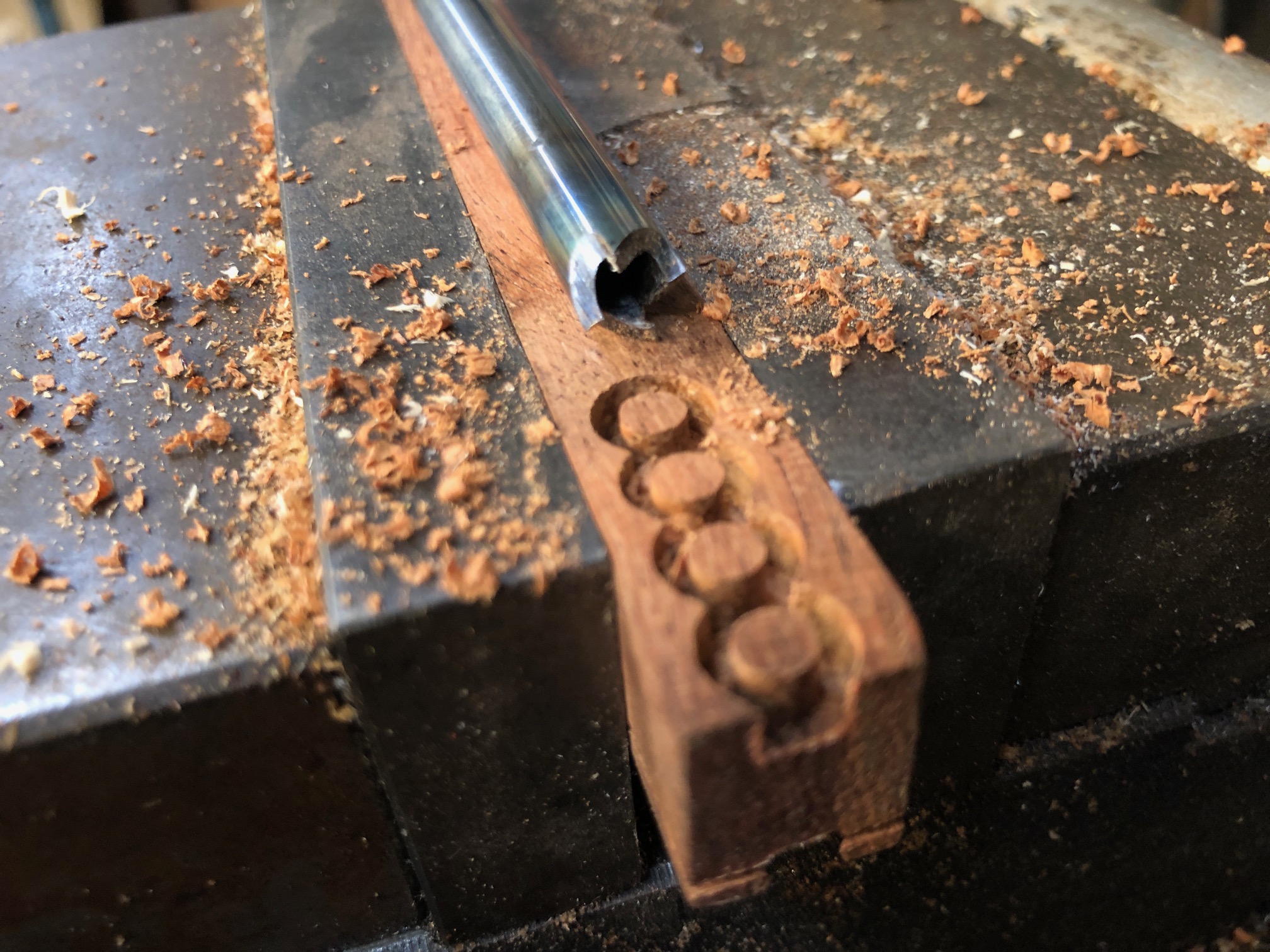
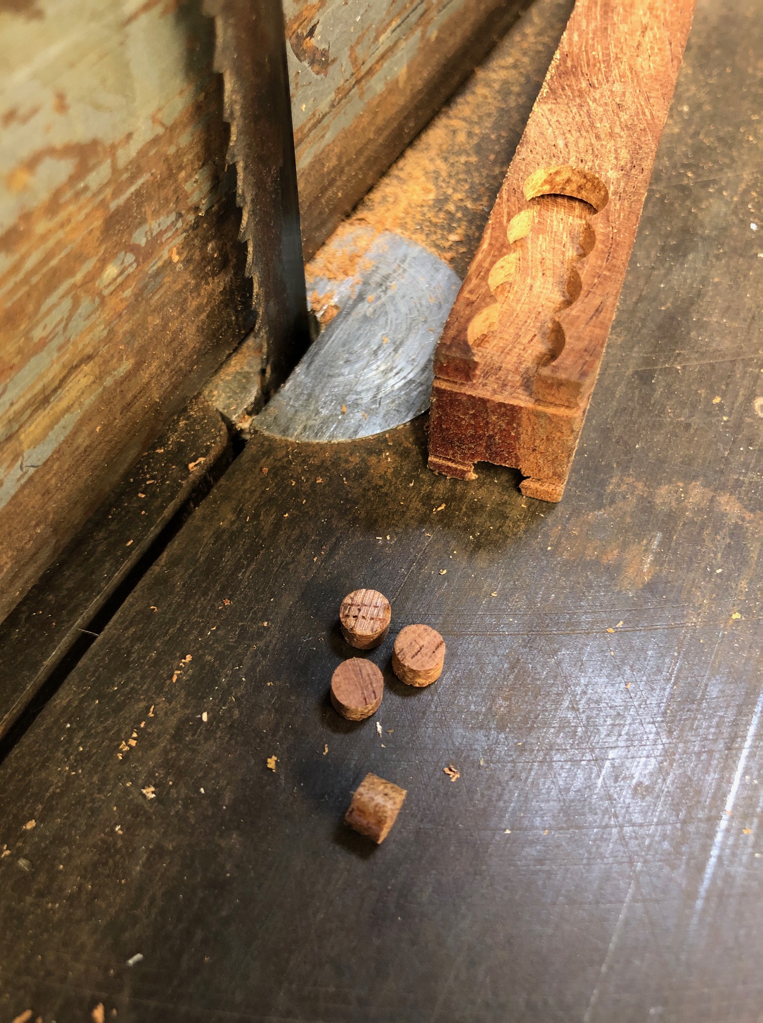
And the result, as you can see, works pretty well. Those deadeye blanks are 4.6mm diameter and 3.5mm deep. The wood is Western Australian Jarrah, which is a nice, tight, dense Australian hardwood. I will try it for the deadeyes.
I used the annular cutter about 100 times, to refine speeds and feeds, and it seemed as sharp at the last one as the first.
While I had the T&C grinder set up, I cut similar teeth at the other end of the annular cutter tube.
So, all excited, I turned on the CNC mill (the big one), but was very disappointed when the computer would not boot up. So, I could not drill the deadeye faces. I think that the computer has died. It is about 20 years old. The LCD screen has been leaking for over a year, and it has been misbehaving for a while… probably hard drive dying, so I am not going to try to fix it.
Another decision. Do I machine the wood blanks to the same thickness as the deadeyes? or thicker, as in the above photo, then saw the off the deadeyes.
Bear in mind that the holes for the face of the deadeye will be the first step, then the annular cutter. At this time I am thinking that I will use the thicker material, as in the above photo.
It is too hot today to go to my workshop, so installing another computer will have to wait for cooler weather.
We are experiencing the hottest summer on record here in southern Oz. Please note, Mr. President Elect.
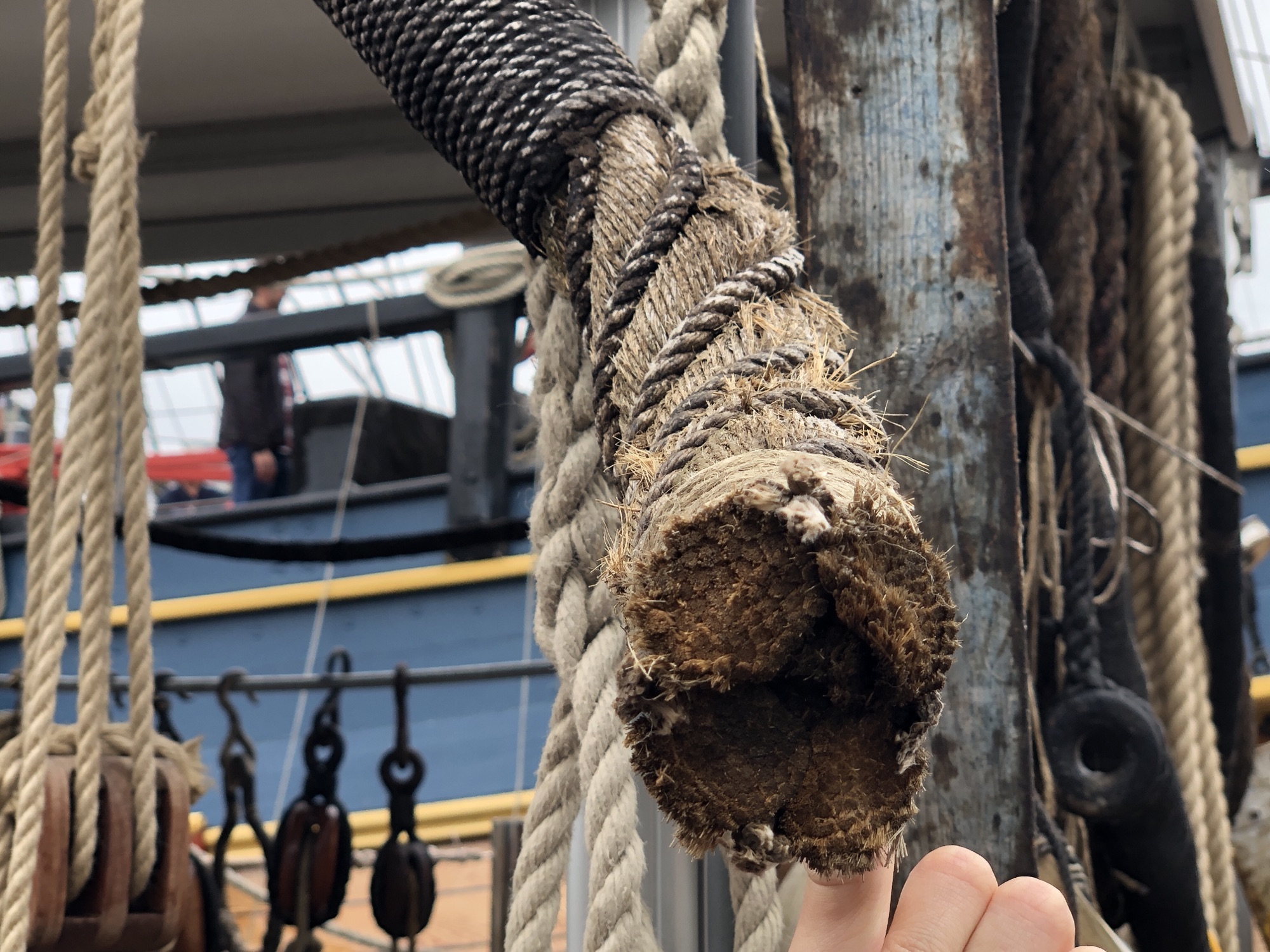
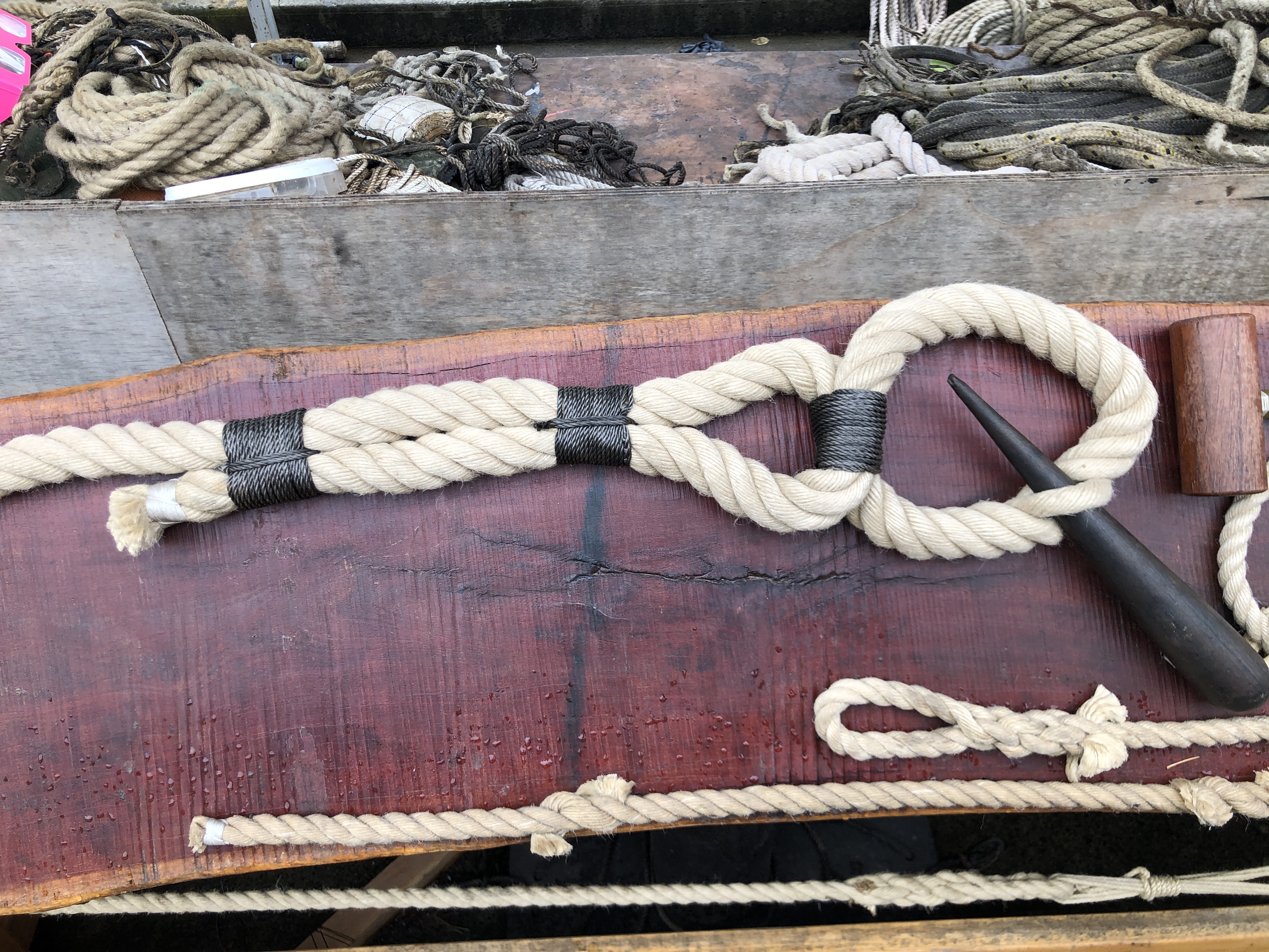
This large cable is covered with a thinner rope (at top), and the gaps are filled underneath. The top section is SERVED and the bottom section is WORMED. Photo taken at HMS Endeavour replica, Maritime Museum, Sydney.and this is an example of SEIZING, where the rope is doubled back, and secured with thinner cord, tightly and neatly wound .
When making a model period ship, as I am currently doing with USS Constitution, serving, worming, and seizing model size ropes is time consuming and tricky for someone like me with dodgy eyesight and limited patience.
When I made the CNC Mini Mill it occurred to me that I could use the mill’s CNC electronic controls to make another CNC machine, to do seizing, serving and possible worming on the scale model ropes. The electronic control box just swapping between the machines.
So I spent some time designing, then making the machine. Not yet tested, but if it works OK I will post a video.
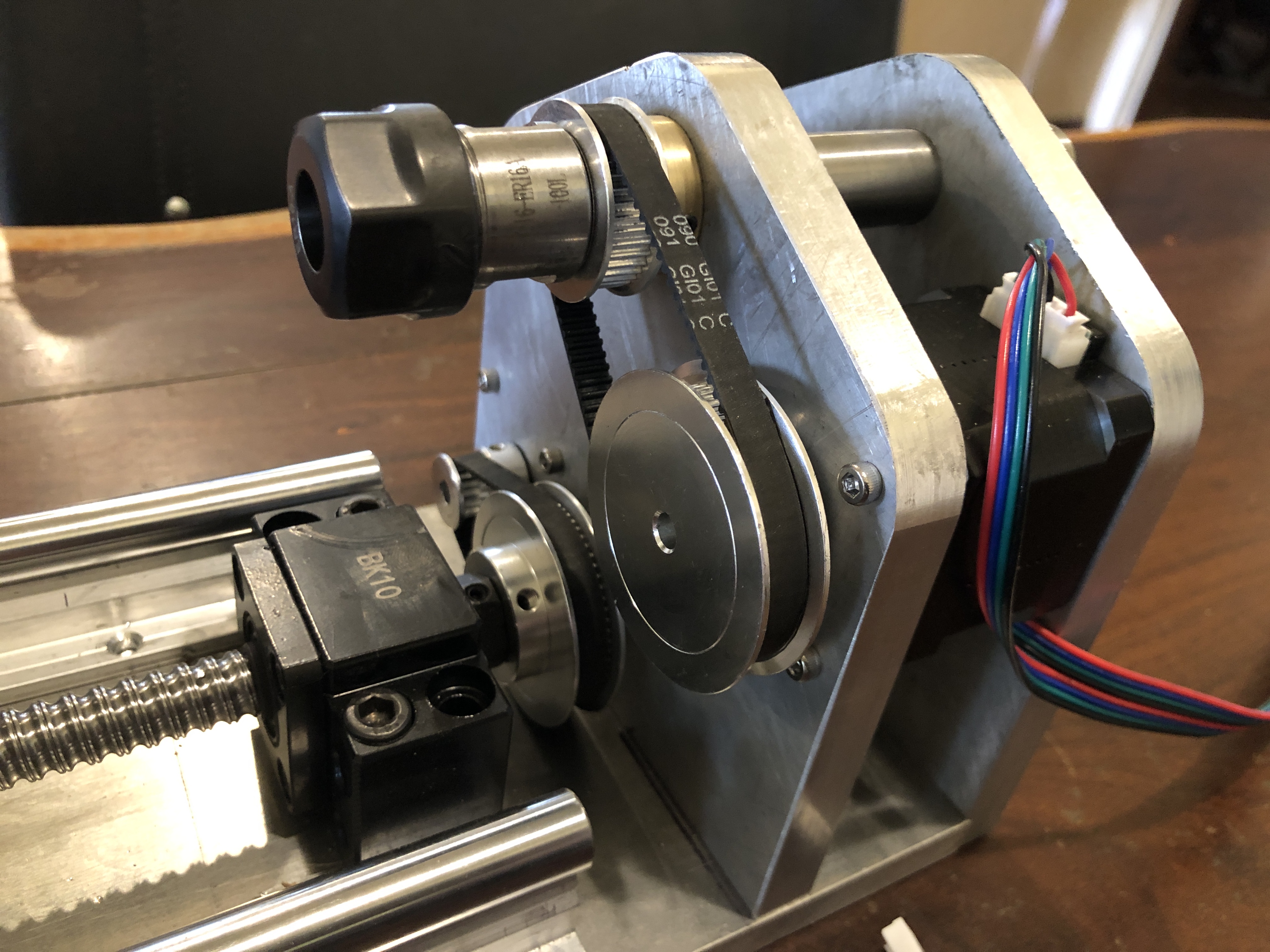
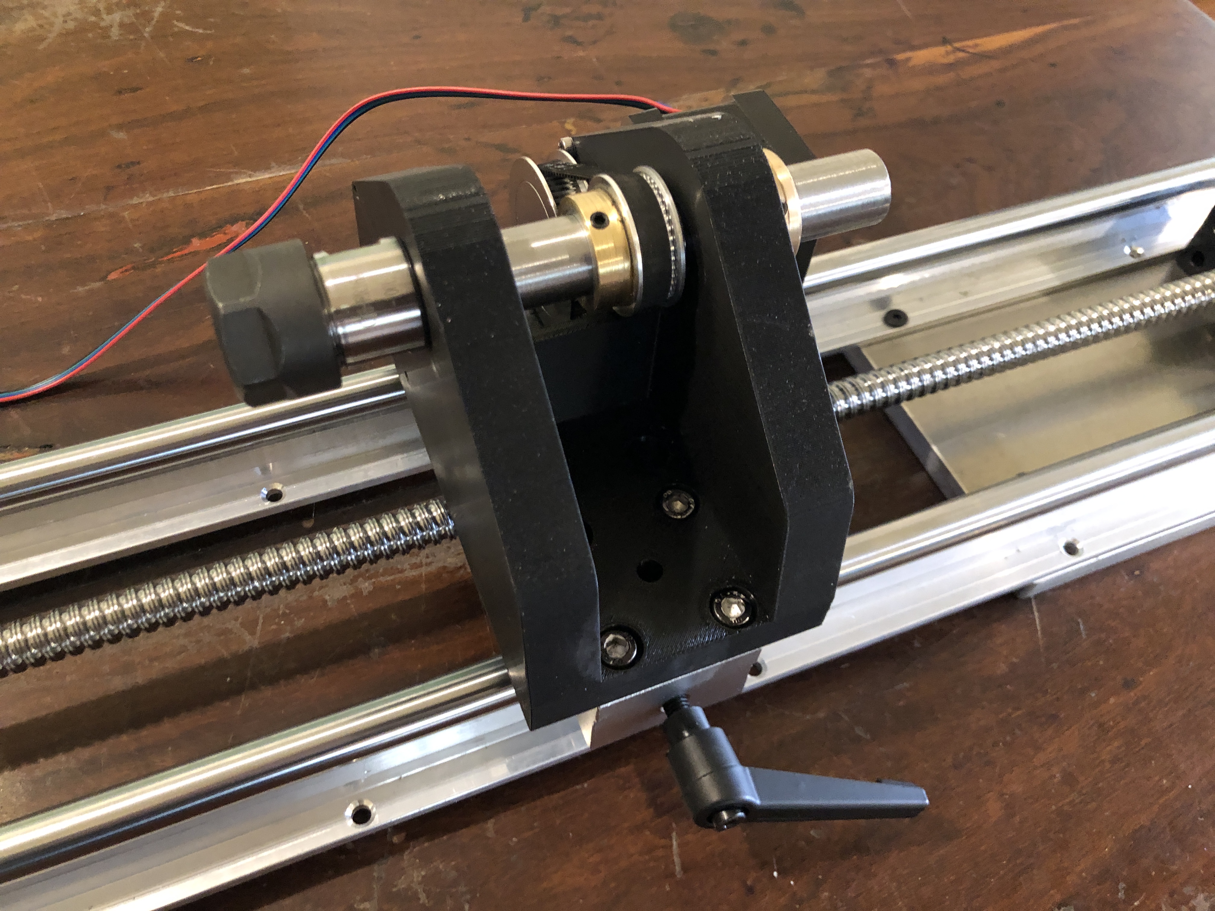
The machine hardware is assembled, ready to hook up to the controls. The rails and ball screw are 1m long. I 3D printed the tailstock and the spool holder. I intended to 3D print the headstock, but had some problems with the print, so I made it from 12mm thick alu.
The electronic controls are set up for Nema 17 motors, which I have used in the mill, and in this machine.
I originally intended to make it to cope with 150mm long ropes, but after some advice from another ship modeller, I expanded the rope capacity to 800mm long.
The headstockThe tailstock.The rope will be stretched between the headstock and tailstock, and supported in the groove beneath the clear cover, and the Gutermann thread is fed through a small hole around the rope. The rope is twisted with Nema 17 steppers at each end, and the assembly is moved at a predetermined rate by the ball screw also powered by a Nema 17 stepper. Fingers crossed that it will work. That is the theory anyway.
I have finished the Mini CNC Mill. It is working, and I am satisfied that it will do the jobs of making small 3D pieces accurately.
Had to sort a few problems. First there was excessive play between the hardened steel 8mm rods and the linear bearings. I had measured the rods at 7.97mm diameter, so placed another order, and eventually received some slightly better rods, at 7.985, but no improvement in the play, so placed yet another order, (different supplier each time), and the final ones were 7.99, and still the play was excessive. Then the penny dropped, and I got some new linear bearings, which solved the play problem.
Next issue was excessive backlash in the acme screw nuts, but that was solved by installing them correctly, after some advice from my engineer friend Stuart. But it did involve a complete tear down of the machine several times before I did it properly.
Finally, I installed all of the boards, switches, power supply, fuse, in the electronics control box. That was fairly straight forward, but I knew that I was not capable of doing the wiring and booked my expert friend Stuart to do the job for me. Despite the fact that he has done the same installation on many occasions, it took him about 4 hours. I was taking frequent photos and making copious notes, so I could post that information here, but frankly, despite having a reasonable understanding of the principles of the workings, when issues arose on first testing, I had no idea how to do the trouble shooting, or how to fix the diagnosed problems. Stuart however sorted the issues quickly and efficiently. ( I imagine that if I was teaching Stuart how to do a Caesarean Section or a hysterectomy, the roles would be reversed.)
So, I am not going post the details of the electronics wiring. But I will post photos of the completed job. (see below).
If anyone does decide to go down a similar path, and is not an electronics expert, my strong advice is to have an expert do that part of the job. It is not for amateurs. The making of the mill, and installation of the electronics components was simple compared to the wiring.
The mill is accurate and adequately rigid for 3d machining of plastic, wood, aluminium and brass parts, using cutters up tp to 3mm diameter.
The final cost of the mill and the electronics control box and manual handpiece, excluding repeat purchases due to quality of some components, was approx $AUD1000. That does not include Mach3 and Vectric V Carve Pro which I had purchased several years ago.
When I make some model ship building components I will post some videos and pics.
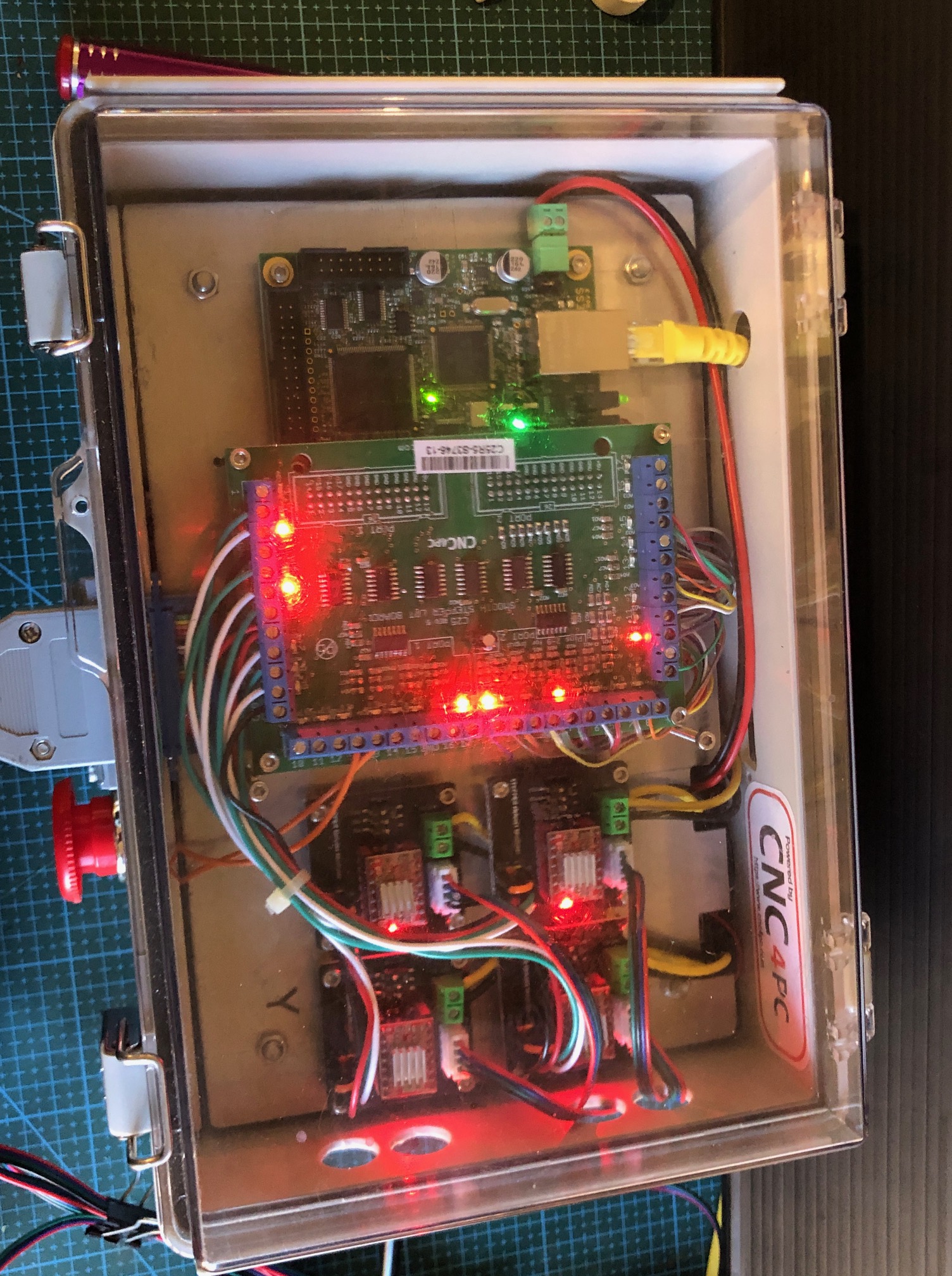
The most expensive component was the electronics box of controls (ESS board, breakout board, stepper motor control modules, switches etc) which was about 2/3 of the total. But with all of those red and green LED’s it is quite a nice display!
Although “finished”, I am planning to add a sacrificial wooden work surface, and a tailstock for the 4th axis rotary table. I think the tailstock will be useful for example for making spars.
And, I will be able to use the electronics box to run the CNC serving machine which is well underway. Again, waiting for components, this time from China.
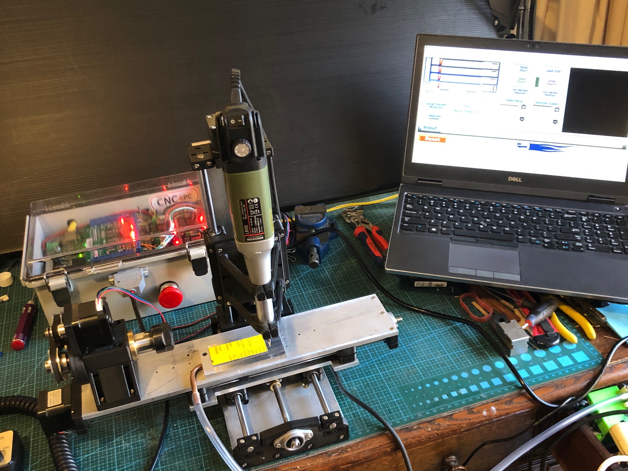
The mini 4 axis CNC mill, electronics control box, and computer running Mach3 and V Carve Pro, sitting on my desk in our TV room at home. The plastic tube is connected to a small aquarium pump which provides suction to the aluminium plate on the mill table and is used to hold down small plastic objects for machining. In this case making name badges. The rotary table will be removed for most CNC machining functions, but I can envisage that it will be used in conjunction with the vertical spindle to make pieces like spars for the Constitution.The electronics box has a lot of appealing flashing lights, indicating various functions. The transparent lid was a must, just for the entertainment.
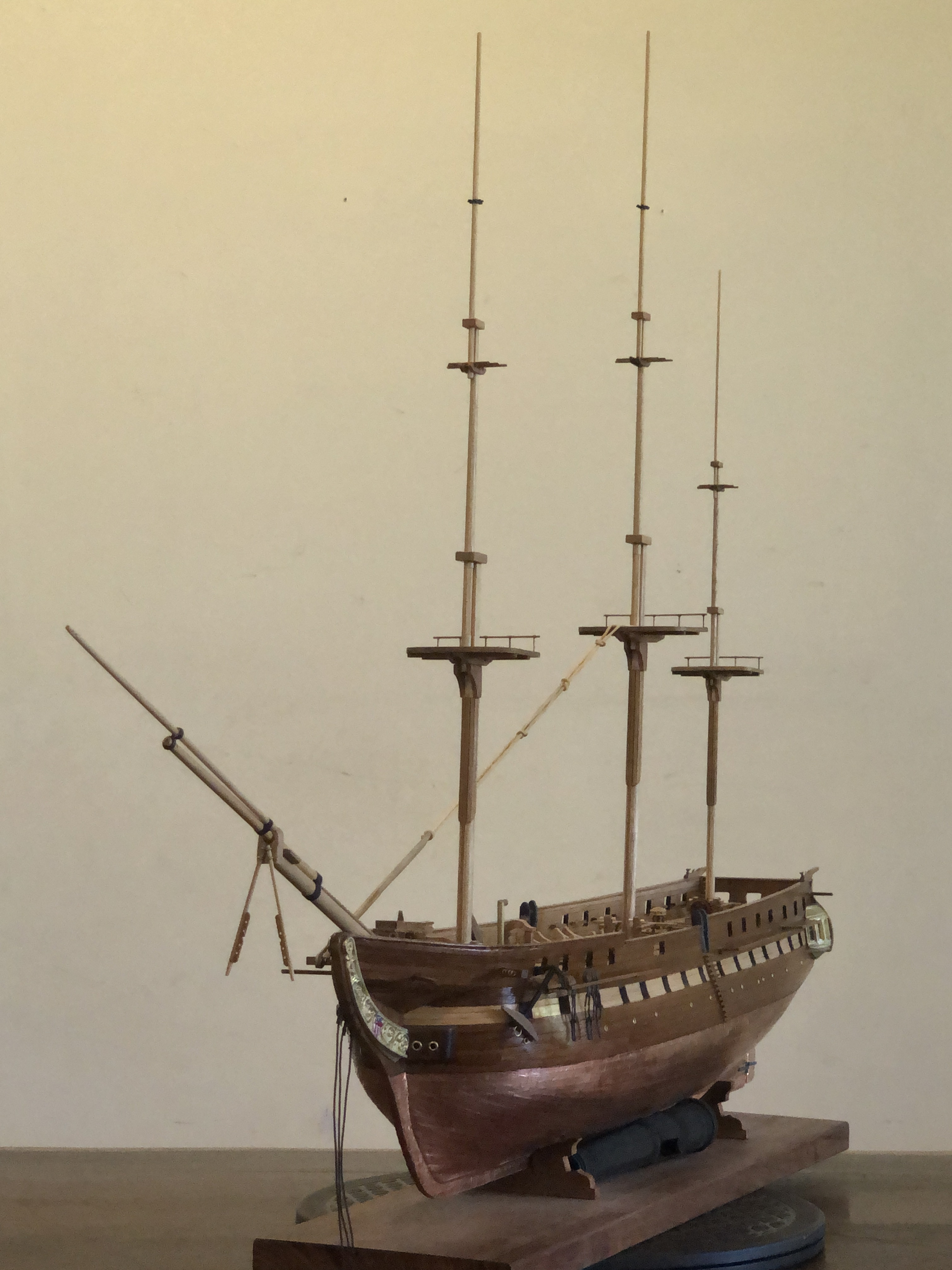
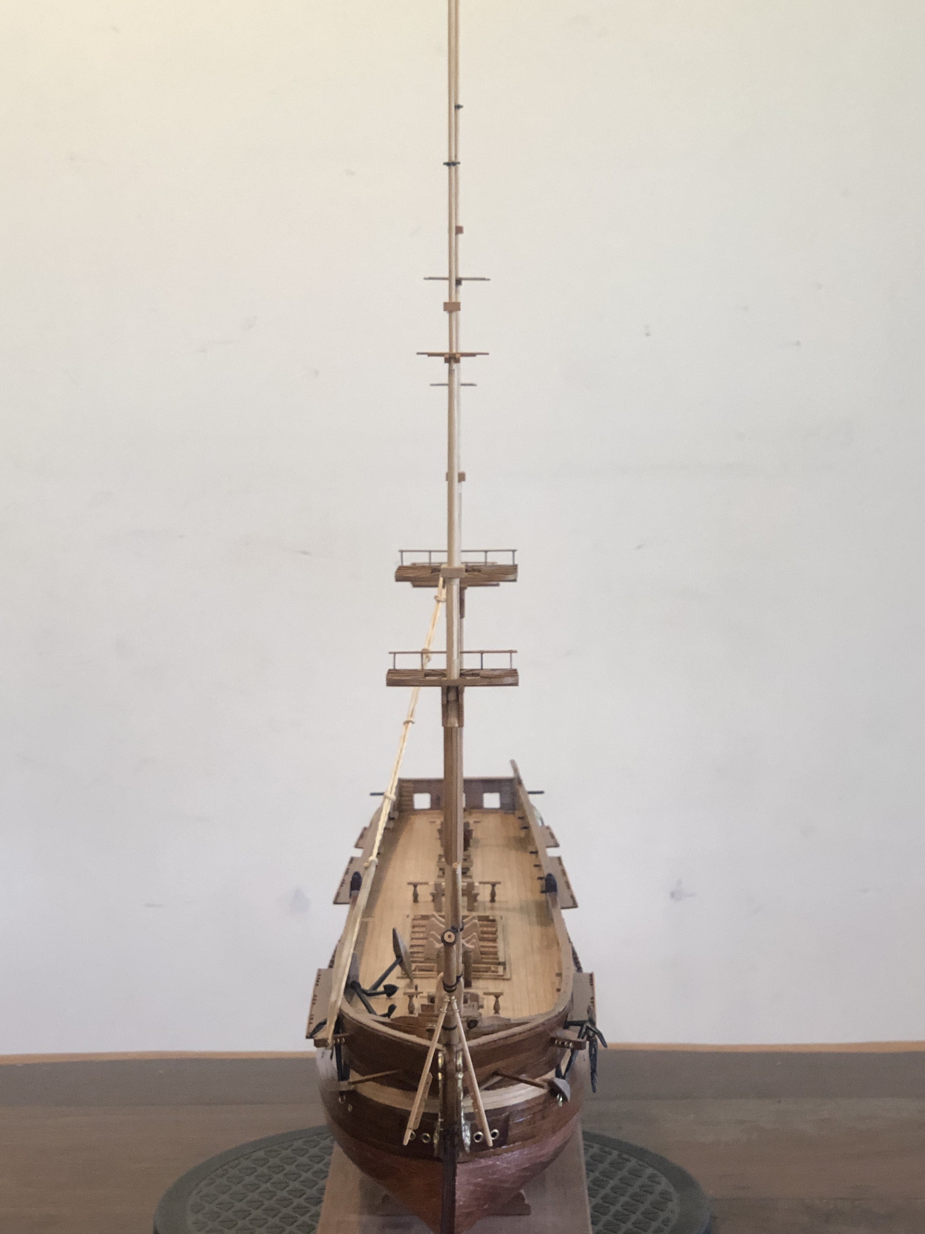
And some progress on the Constitution. I have made the masts and bowsprit, and they are now siting in position, ready for the standing rigging.
Since this photo was taken I have used fine copper wire to temporarily hold the masts in position.Carefully lining up the masts and getting the rakes correct. Sailing ships captains could vary the fore and aft masts angles varied to improve the ship’s steering and handling. I have chosen 2deg rake for the foremast, 3 for the main and 4 for the mizzen.
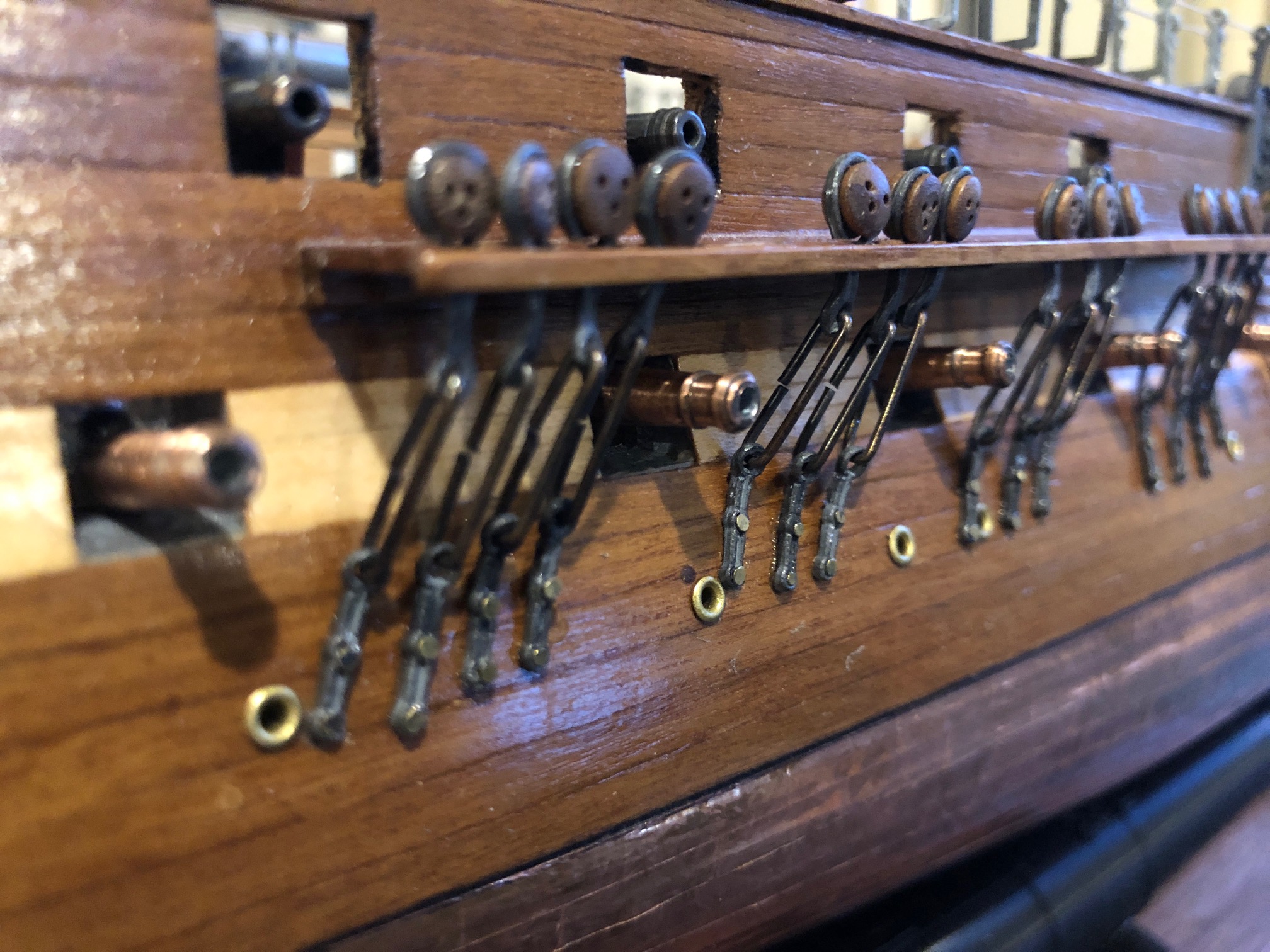
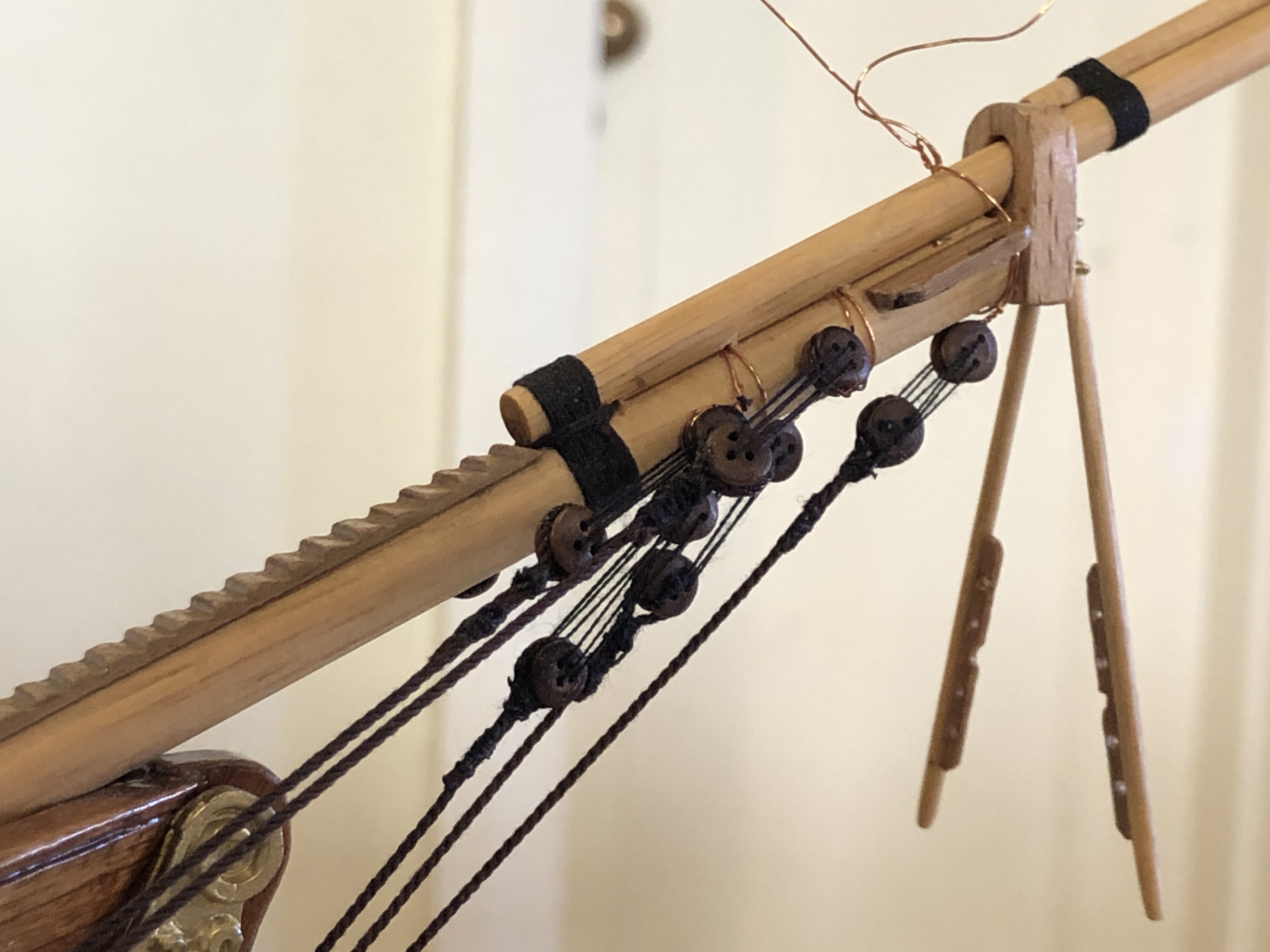
And here is the first standing rigging. On the bowsprit, showing the initial blocks and stays. Also showing the temporary copper wiring. I do wonder about the size of the blocks as supplied in the Mamoli kit. Maybe a bit too big? My seizing has improved a little with experience, but still not good enough, Now waiting until the CNC seizing-serving machine is finished.
The Southworth steam powered boiler feed pump has many gaskets. I have not counted them, but there must be 15-20. All with many 2mm and 4mm holes.
And in the process of making the machine, I have broken quite a few of them with the multiple assemblies and tear downs.
But, fortunately, 2 of the members of my model engineering club have laser CNC cutters, so extra sets of gaskets has not been an impossible ask. (Thank you Brendan and Stuart!)
So, some time ago I asked Stuart, if it would be possible to attach a laser cutter to the CNC mill. His initial answer was NO. But recently, he changed his tune. He attached a laser head to his 3D printed CNC mill and started producing gaskets on request! So, as is a recent pattern, I am walking in Stuart’s footsteps, and I have purchased a 15 watt laser head on Ebay. Chinese of course.
This is the kit. Cost $AuD146.
And this is the 15w laser head. Now I have to work out how to attach it to my mill. Shouldn’t be too difficult, as long as I don’t turn on the spindle while it is attached.
My CNC mill, during the electronics upgrade. Most recent photo. Soon to have a laser head.
Stuart assures me that Mach3 can be configured to operate the laser…. turn it on and off, move the axes at an appropriate speed, etc. I think that some trickery is involved.
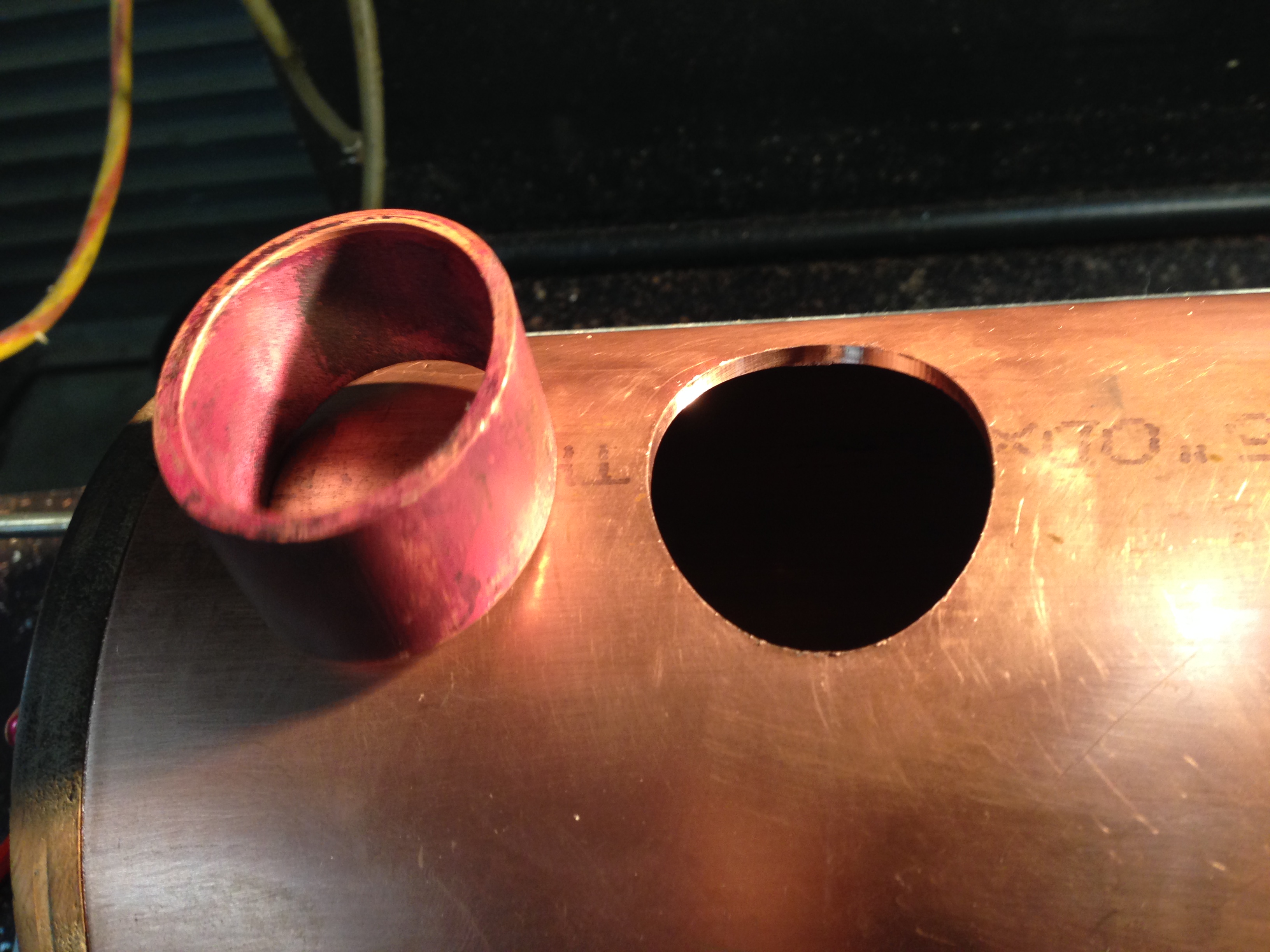
The firehole is the opening where coal is shovelled into the firebox. It is oval shaped, and is exposed to the boiler pressure. It is made from thick copper tube. Oval holes must be formed through the boiler wrapper and the firebox wrapper.
The elliptical hole in the boiler wrapper, and the firehole tube.
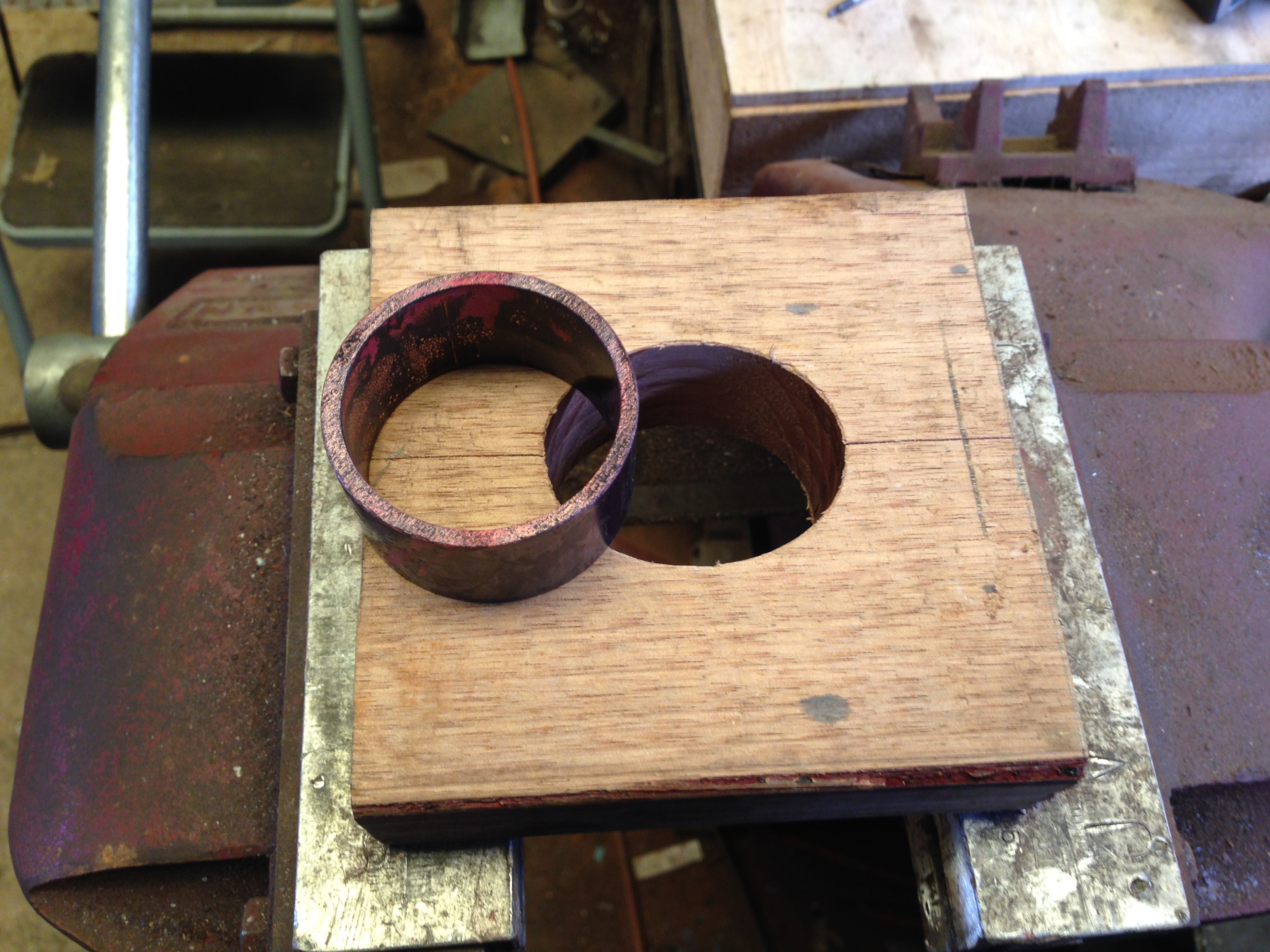
The first task is to shape copper tube which is circular, into oval shaped tube. I decided to make an oval shaped split wooden form and to compress the annealed copper tube with the form.
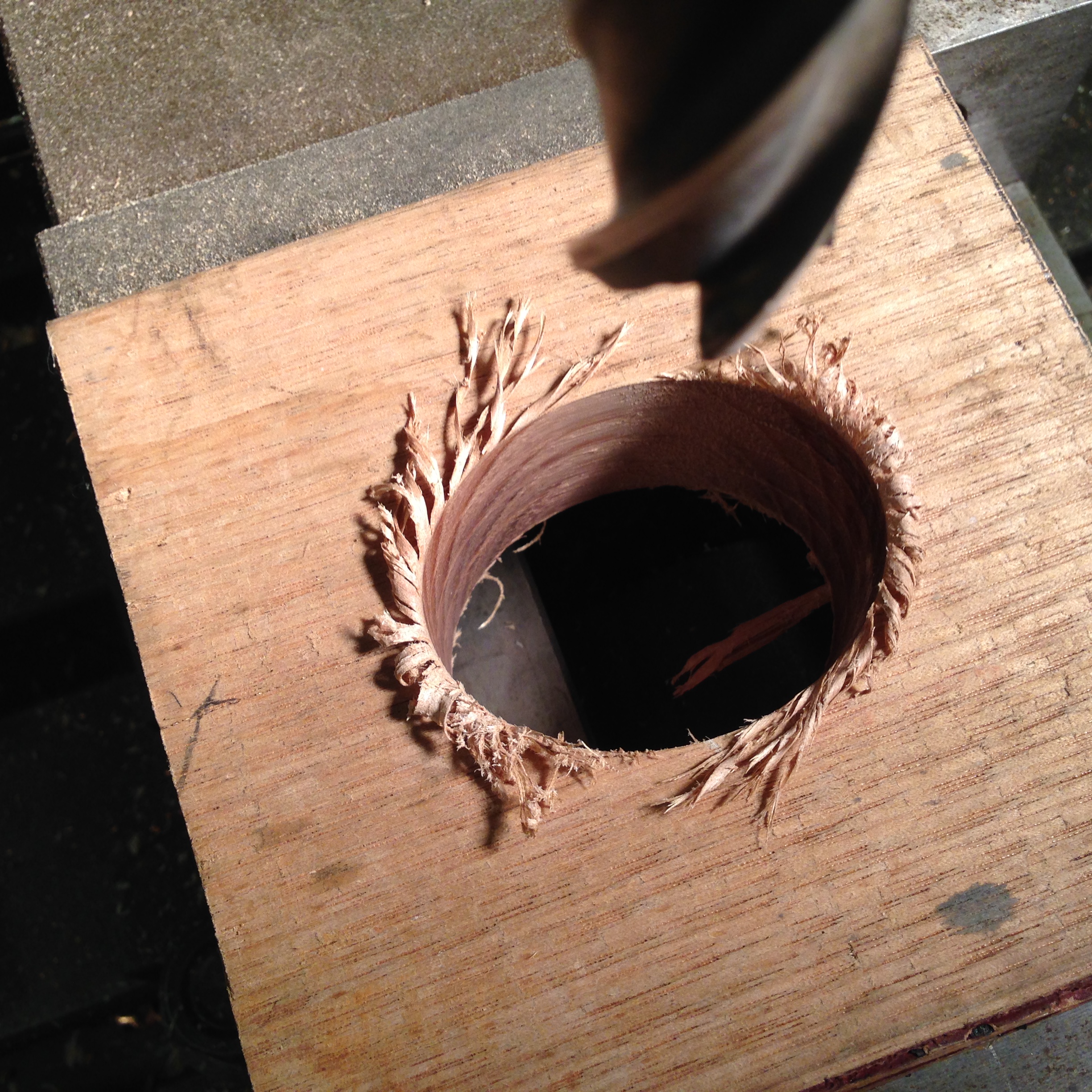
The wooden slab is cut into 2 pieces which are then cramped together, and the oval hole is CNC machined.
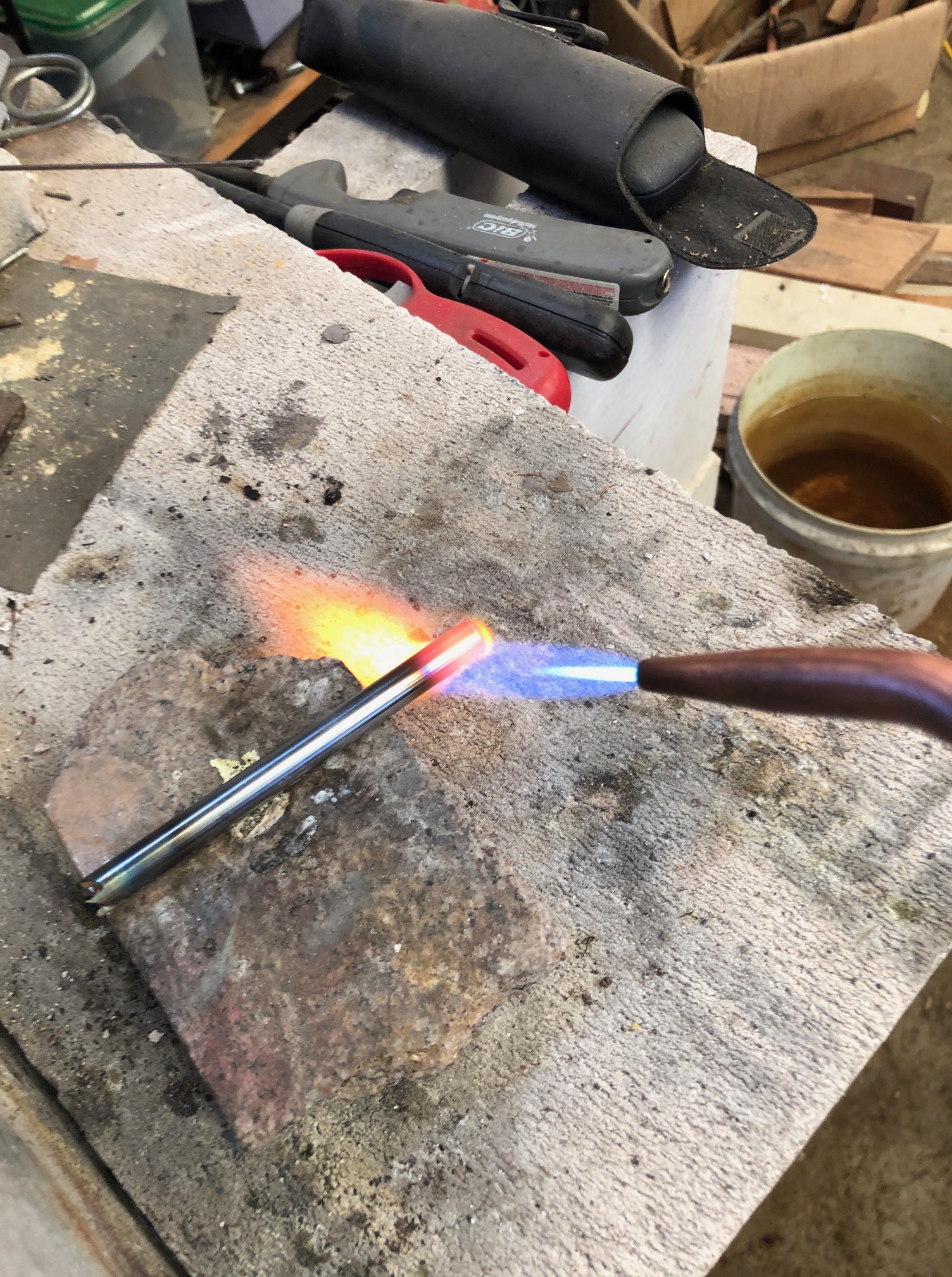
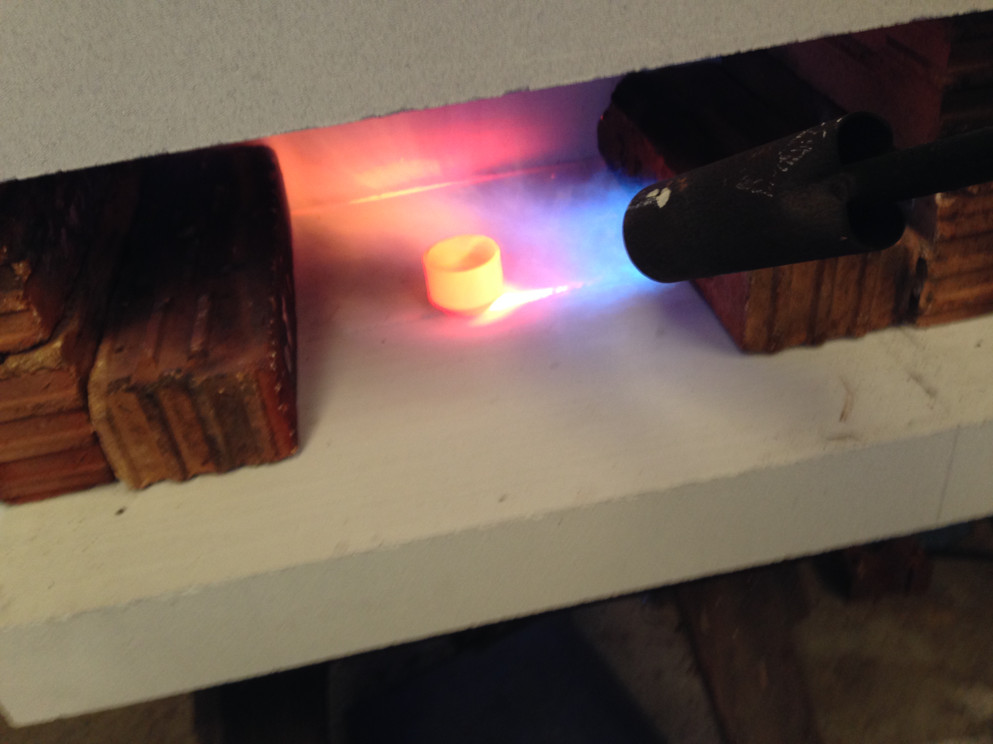
A 1″ 25mm length of 3.2mm thick walled tube is cut off, then annealed. Note that I have upgraded my forge. I bought some aerated concrete blocks (Hebel), and enlarged and encased the forge. The white Hebel blocks reflect the heat and the forge temperature rises quickly. the outside of the forge remains quite cool, testimony to Hebel’s insulating properties. Hebel is quite inexpensive. A 600 x 200 x 100mm blocks costs $AUD4.60. Heating time is 60 seconds, vs 90 seconds with the previous setup.
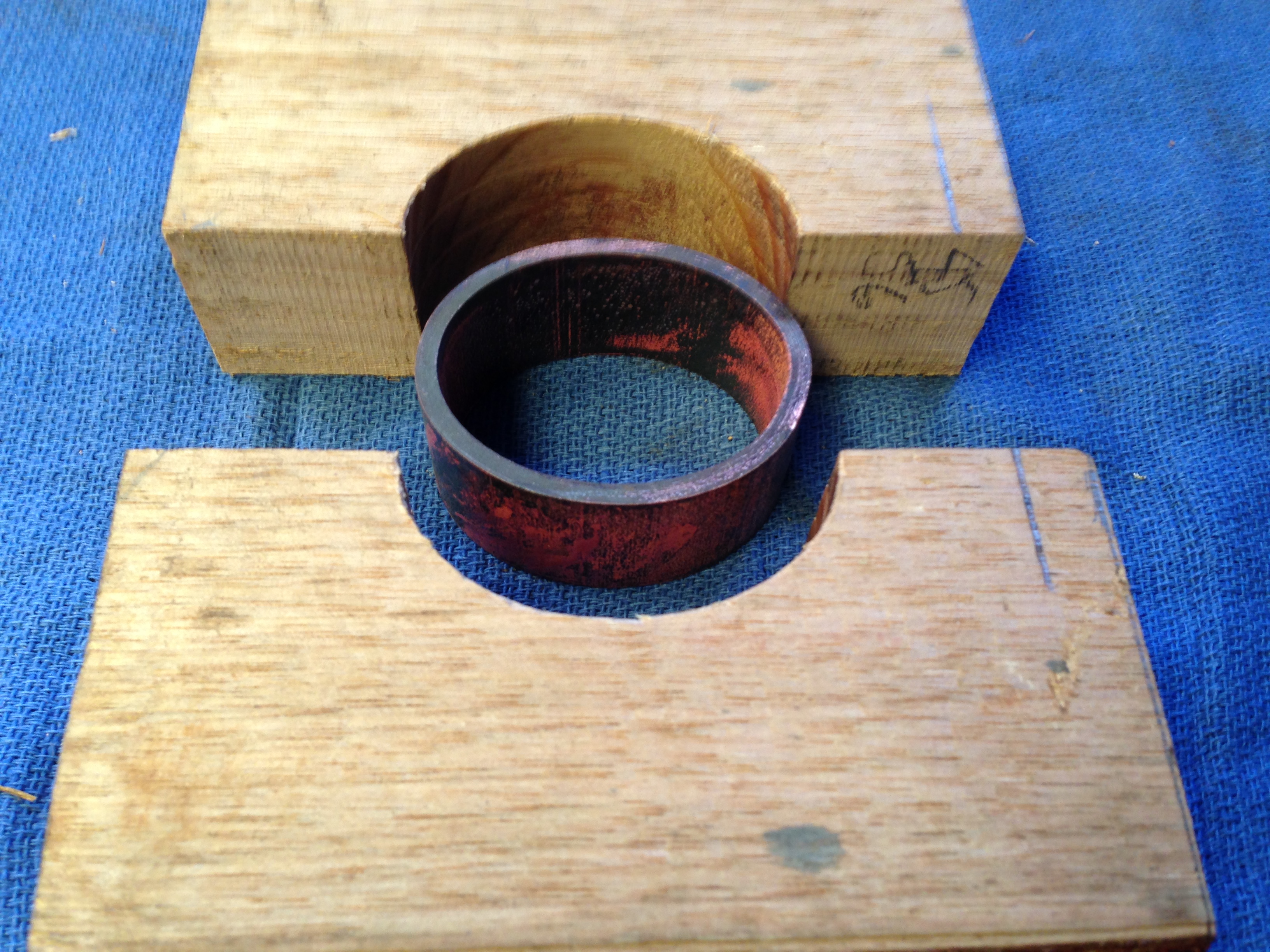
The wooden form and the unshaped thick walled copper tube.
After squeezing the annealed coper pipe in the form, using a 6″ vice. Nice elliptical shape. Note the pencil witness mark.
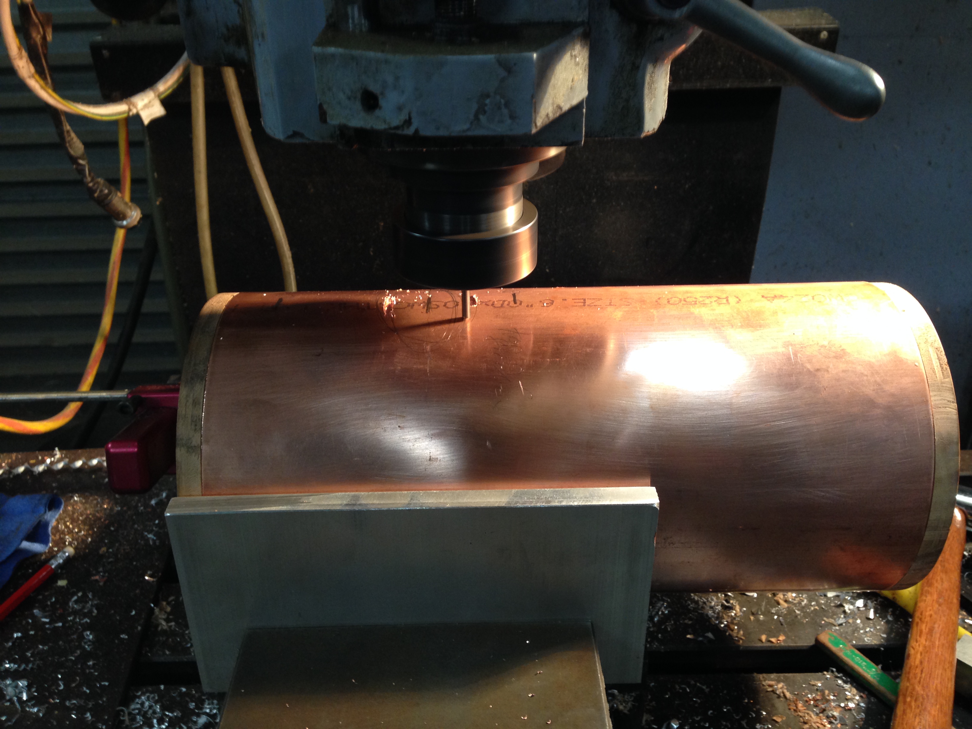
Then the elliptical hole is cut into the boiler wrapper. The vice jaws were replaced by temporary aluminium jaws 4″ high, adequate to hold the 6″ diameter tube. Cutting the elliptical hole on the CNC mill. There are wooden plugs in the boiler tube to prevent the boiler tube from distorting
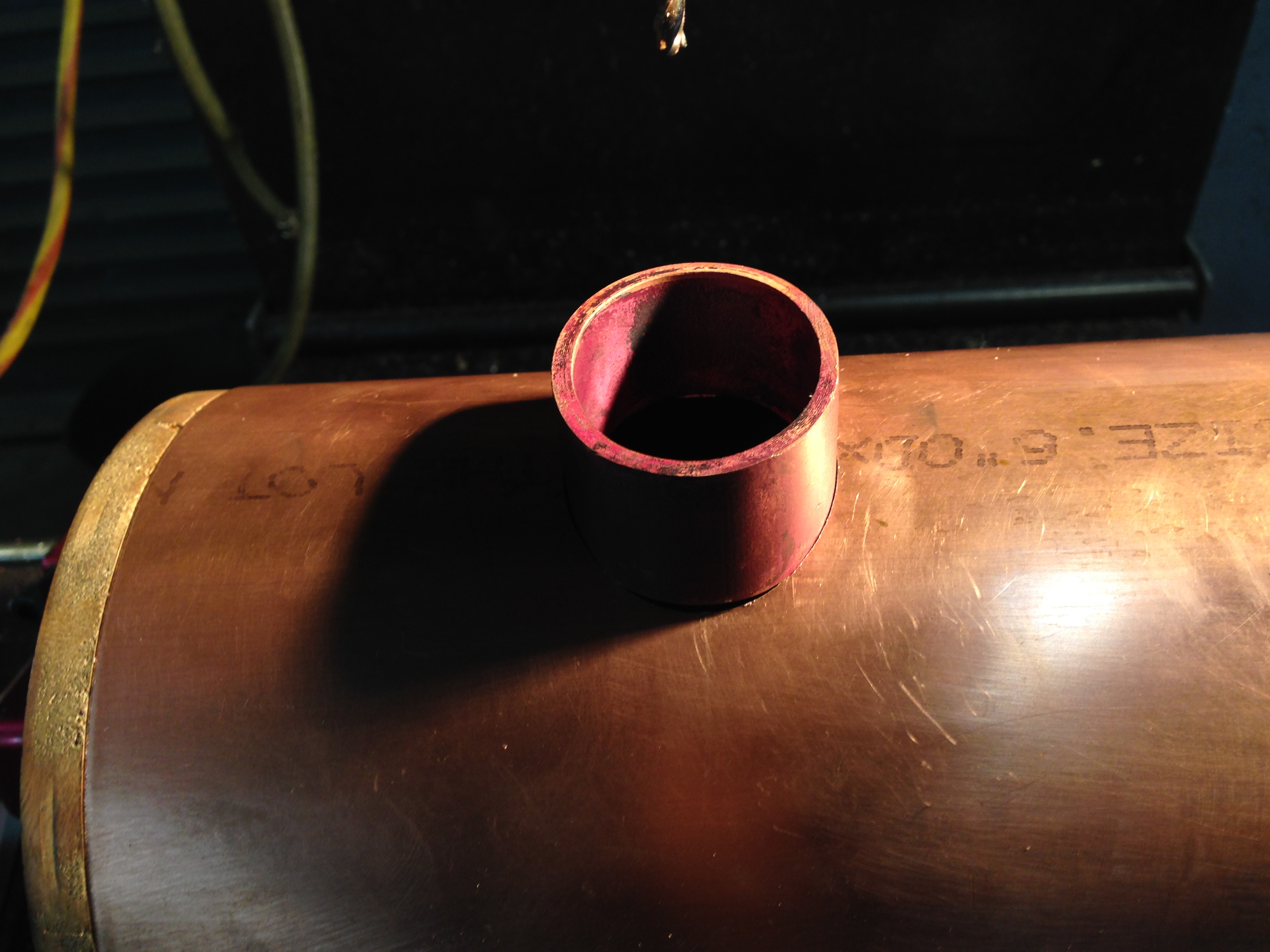
The finished boiler hole and the elliptical insert. This was tense machining.
The fit is a bit too tight. I will take off another 0.1mm so it is an easy sliding fit, suitable for silver soldering. Then to cut the same elliptical hole in the firebox wrapper, but while the main cylinder is set up in this position I can cut openings for the ashpan and safety valve bush.
While finishing the triple expansion steam engine, I have decided on my next project. Actually, based on my past history of procrastination with the triple, I might even put aside the triple to start on this one.
Reading this article in “Model Engineers’ Workshop” gave me the inspiration to convert a rotary table to electronic control.
Dec 2016 MEW article
So I have commenced accumulating the bits and pieces…
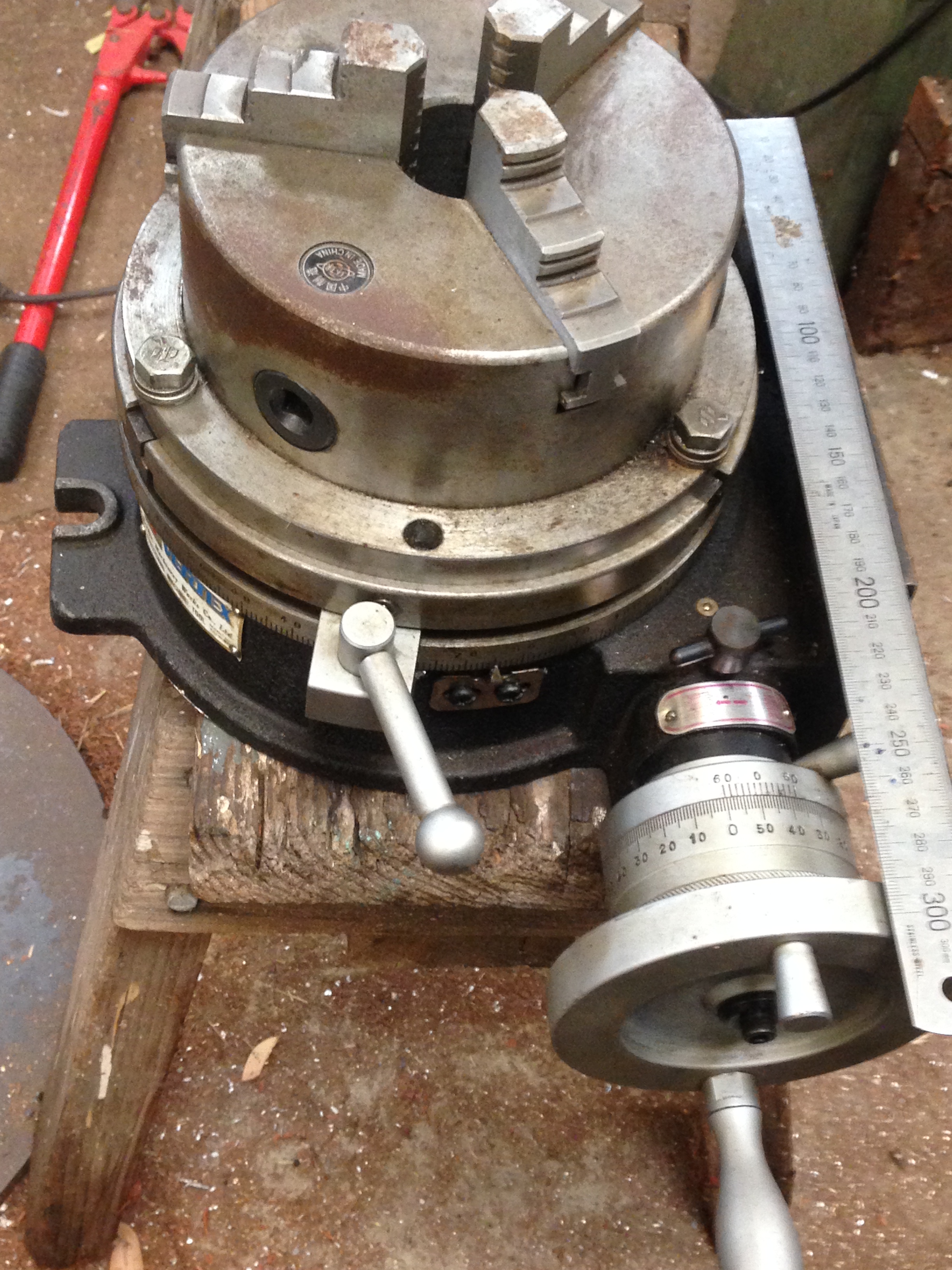
An 8″ Vertex rotary table. I have had this for years, but unused since acquiring a universal dividing head. Should be ideal for this project.
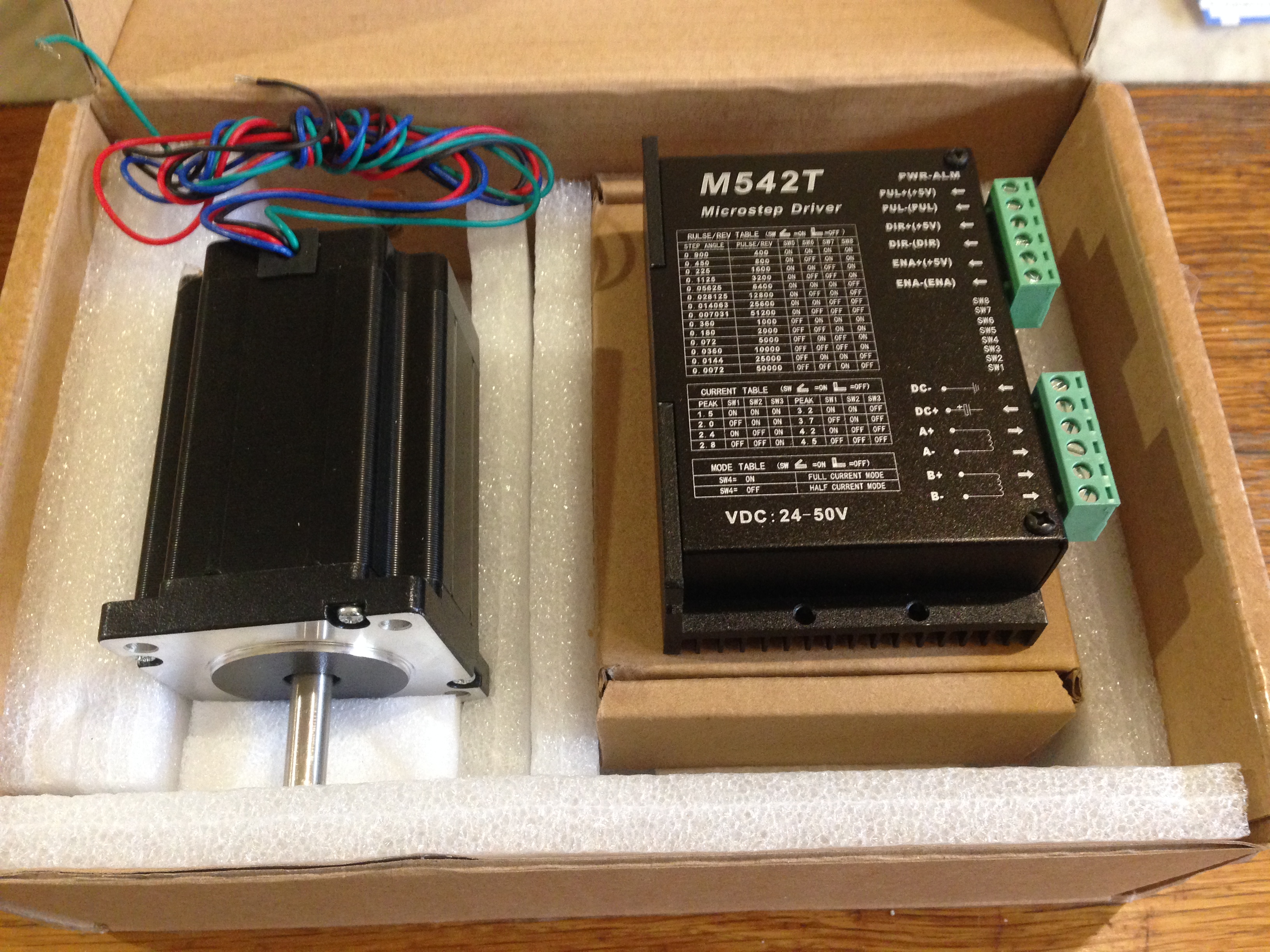
A Nema 24 Stepper motor, shafts at each end, so I can use the table manually as well as electronically. The Microstep driver was supplied packaged with the motor as a kit. $90AUD inc postage.
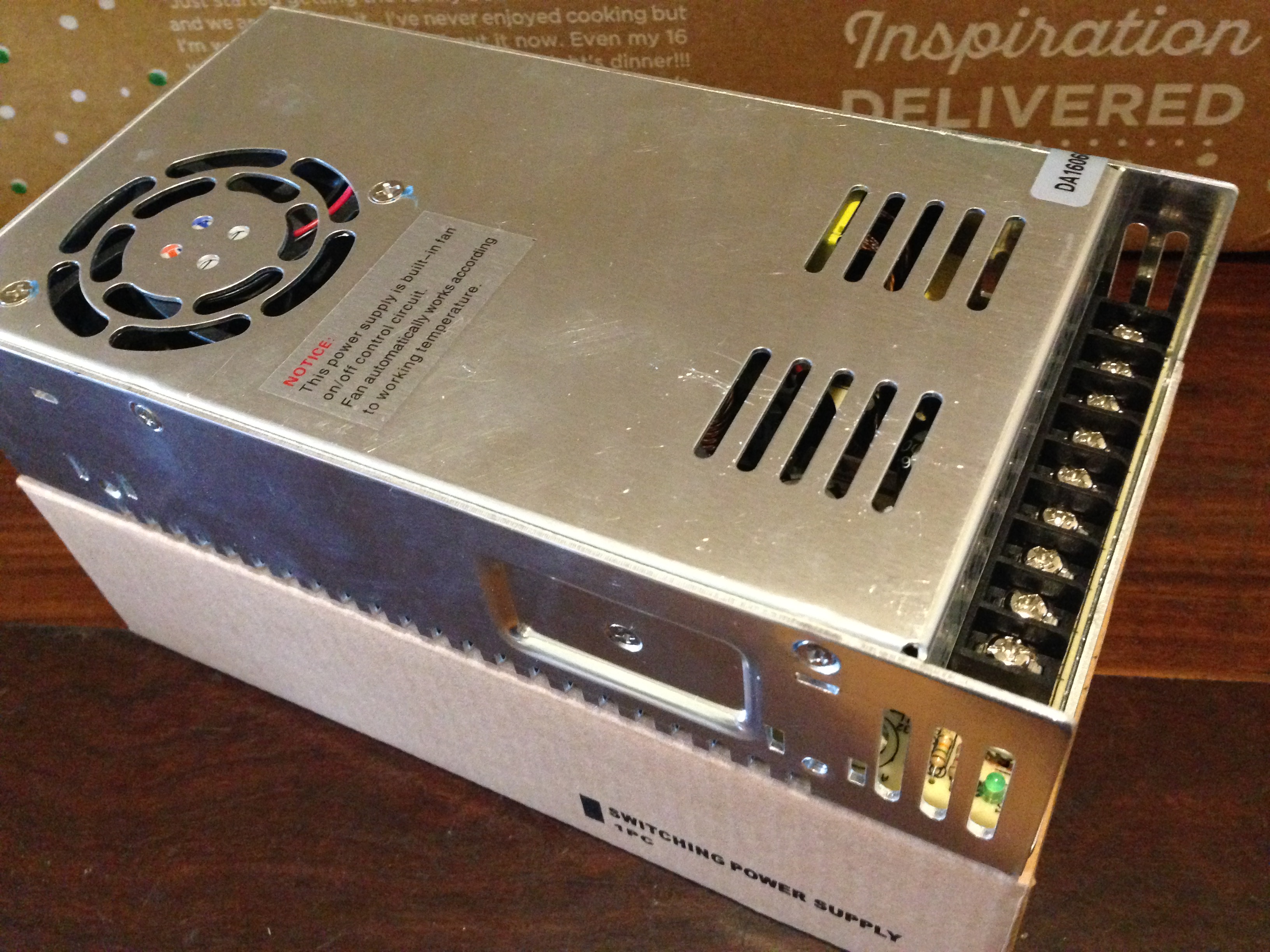
From the same supplier, a 48volt power supply. $38AUD
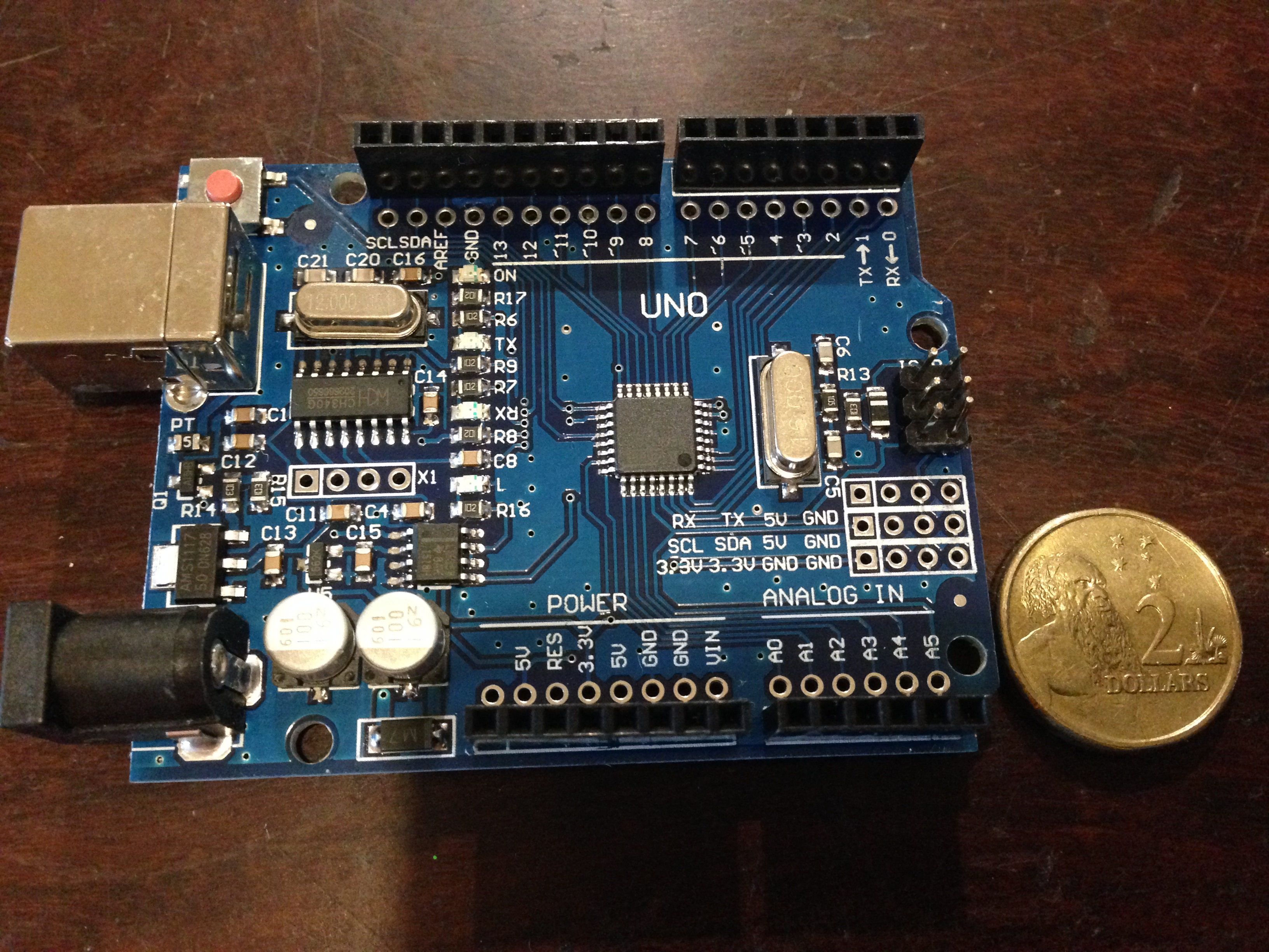
The brain of the system. A programable microcontroller “Arduino Uno”. I bought 5 of these for $20AUD post included.
And an easily attachable display. To attach the Arduino. $19AUD
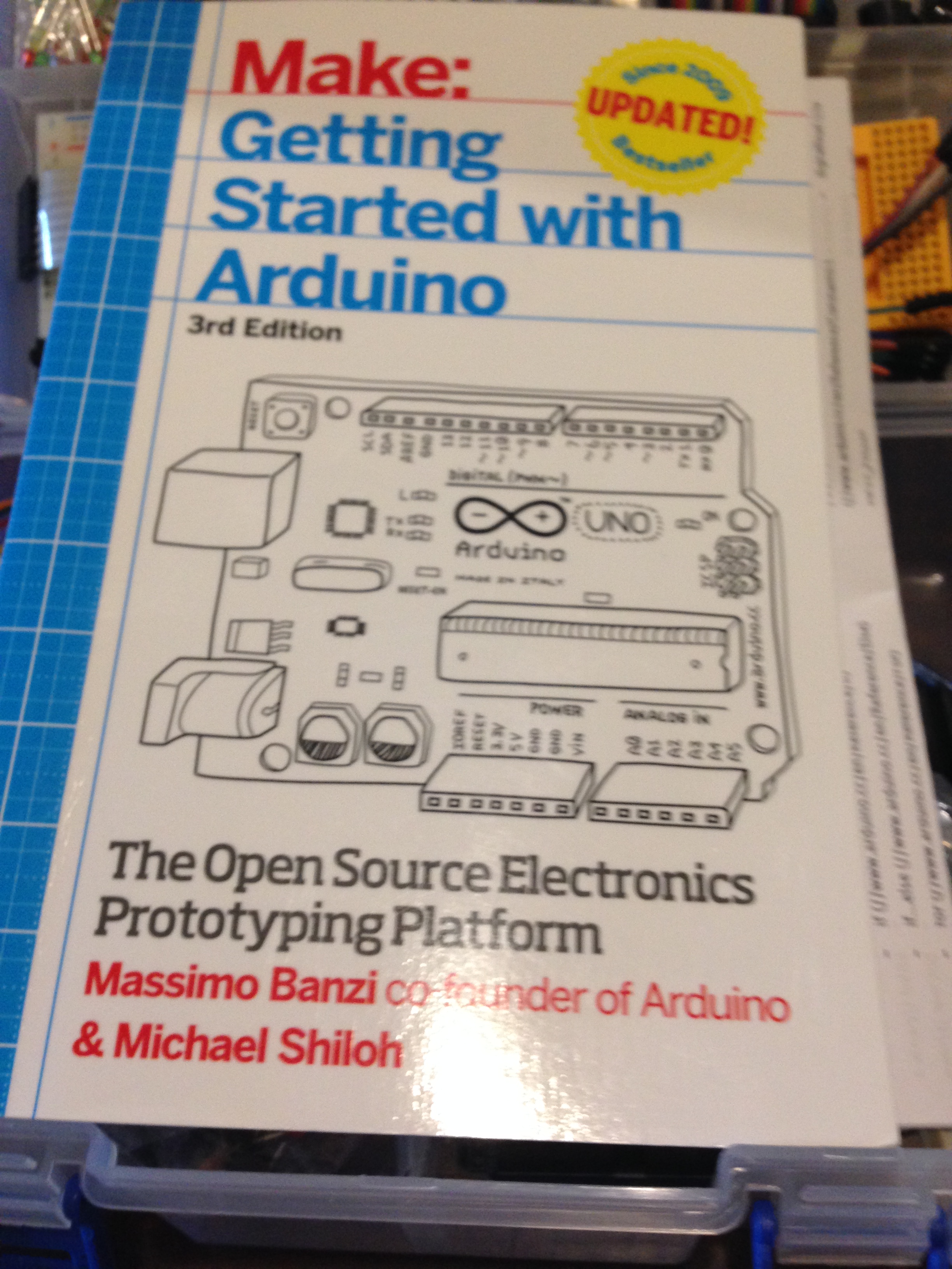
And since I knew nothing about Arduinos, a “Getting Started” book. Excellent. On loan from a friend (thanks Stuart)
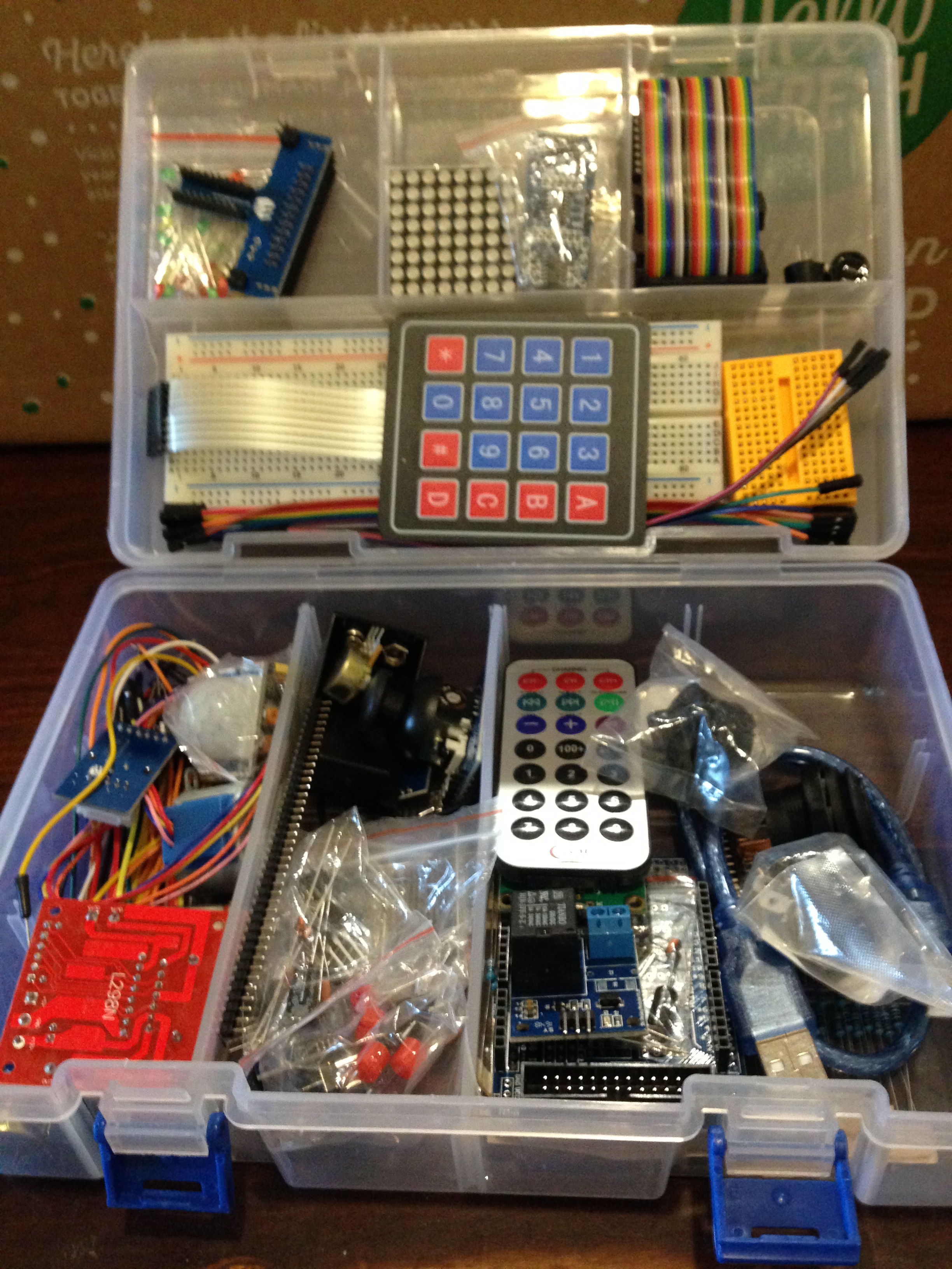
And to practice some circuits and get some idea about the Arduino programming, a starter kit of bits and pieces. $75AUD, but has been very instructive and loads of fun. The program to run the Arduino is downloadable free from the Internet, so this kit might be a bit superfluous.
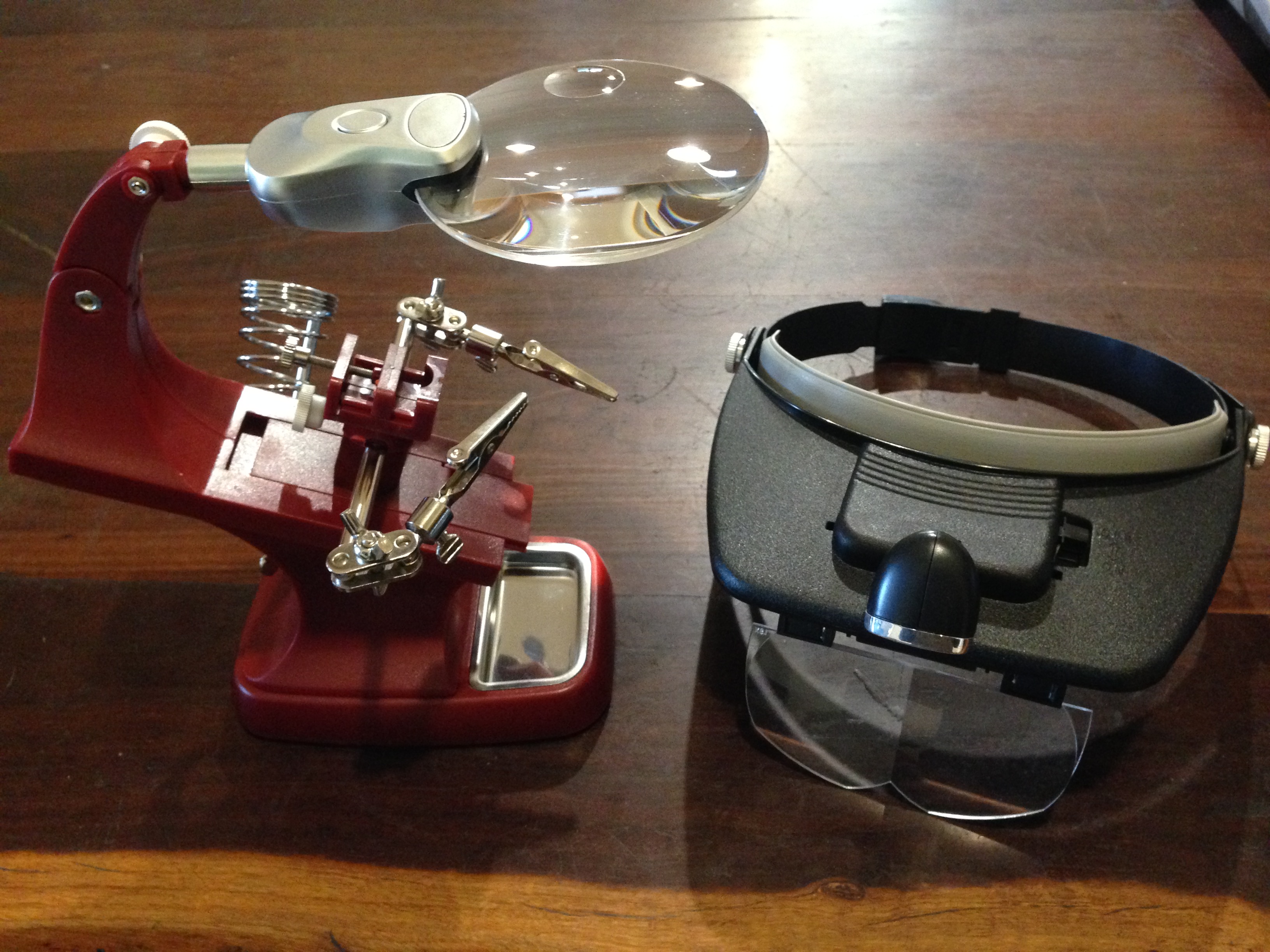
And some items of kit. Each under $20AUD.
A magnifier soldering station, and head light and magnifier
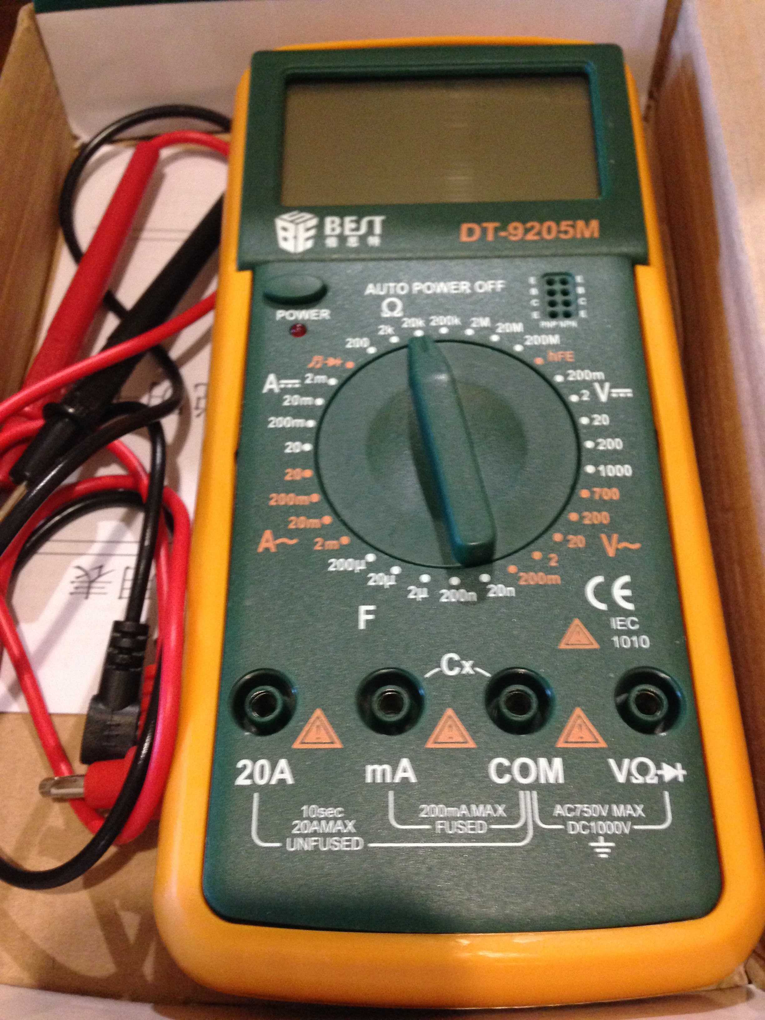
A very cheap multimeter. Previous purchase. Works fine. $10AUD
I have disassembled the rotary table, and ordered a 12/8mm coupler. I am waiting for the coupler before I start designing and cutting the main part to be fabricated which is the piece which joins the stepper and the table.
Also ordered a box to contain the electronics and switches. Havn’t yet thought about cables, joiners etc.
Another session or two, and this project is complete.
Now how do I make a cannon ball 62-63 mm diameter? In wood will be ok? Does not have to be granite. I could make a mould and cast it in aluminium or lead, but stone would be authentic….. thinking.
ps. Re cannon balls. I will cast them, in cement! Now, how to make a mould.
After some test runs without tool or material, I performed some measurements.
500mm movements along the Z axis were reproduced multiple times with a deviation of 0.00mm! (the Z axis has a ground ball screw)
100mm movements along the X axis deviated 0.02mm. (the X axis has a rolled ball screw).
I was delighted to note that the lathe is extremely quiet and smooth. The only noise is some belt slap from the very old belts, and from the stepper motors.
The video below was taken from my iphone, while I was operating the lathe controls, so please excuse the erratic movements.
The steel is 27mm diameter. 750rpm, 50mm/min feeds.
And the guards will be made next step, without fail.
The G code was generated using Mach3 for these very simple shapes. For more complex items I use Ezilathe.
The lathe is 600mm between centres. 38mm spindle bore. Swing about 300mm.
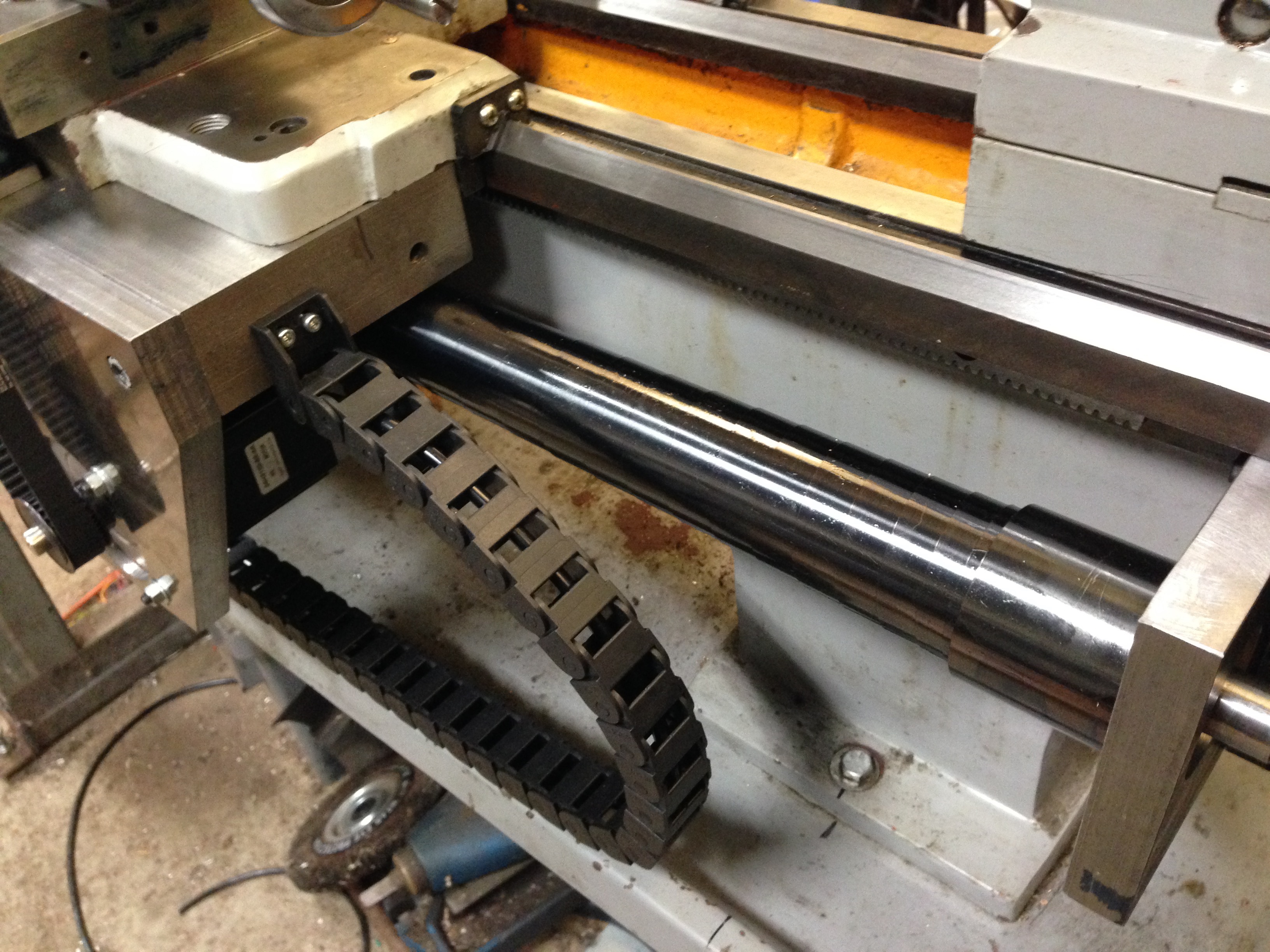
Another couple of advances in the conversion. Today I installed the lead screw cover and the cable protector to the cross slide stepper motor.
The cable protector was easy and straightforward. It flexes in one direction only, and is fixed at the ends after the cable is threaded through it. The length is adjusted by adding or removing links. It was placed so that coolant liquid will drain out of it, and to minimise the accumulation of swarf. The cables themselves have a thick covering and are well protected. The link protector will not kink, further protecting the cable.
It was cheap. About $AUD20 for 2 meters, posted from China. I used about 1.1m.
Showing the stepper motor cable protector, and the lead screw protector (one half of it. The other half is on the other side of the carriage.)
The lead screw protector was another story. It is a spring steel coil, about 50mm wide, and as it is compressed the coils fit inside each other. I made a big mistake in allowing it to spring open before I had installed it (there were no instructions). It immediately opened to a length of over a meter, in coils about 50-60mm diameter. No big deal, I thought. I will just compress it back to its original configuration. Big mistake.
It was what I imagine coiling a live, oily, biting, boa constrictor would be like. (OK, boas constrict rather than bite. How about an anaconda, or a big eel.)
I fought it for about an hour. And eventually succeeded. Minus a few bits of my skin.
So I did not allow the protectors to expand again until after I had them on the lead screw.
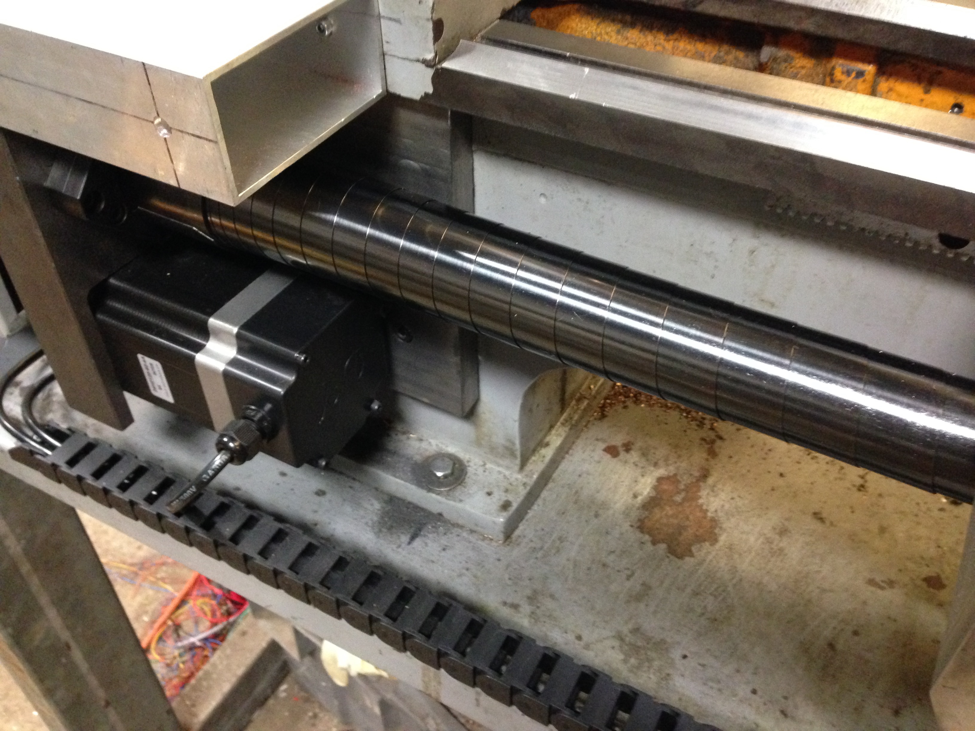
This is what they look like. Pretty cool IMO. They just expanded into position when I removed the restraining clips.
The lead screw stepper motor and protector. The Estop box above will get some ends to exclude swarf.
It was not cheap. The best price that I could find was from South Korea. $AUD200 inc postage. But it is excellent Japanese quality.
The wiring is happening, but the variable speed drive seems to be dead. It has been sitting unused on a shelf for 2 years, so no point asking about warranty. Took it apart to check for broken wires, fuses, burnt out components etc, but nothing visible. Will order another one. About $AUD200. An unexpected expense.
These lathe CNC conversion posts are probably becoming a bit tiresome, but just in case there is someone out there who is interested, I will continue until the job is finished.
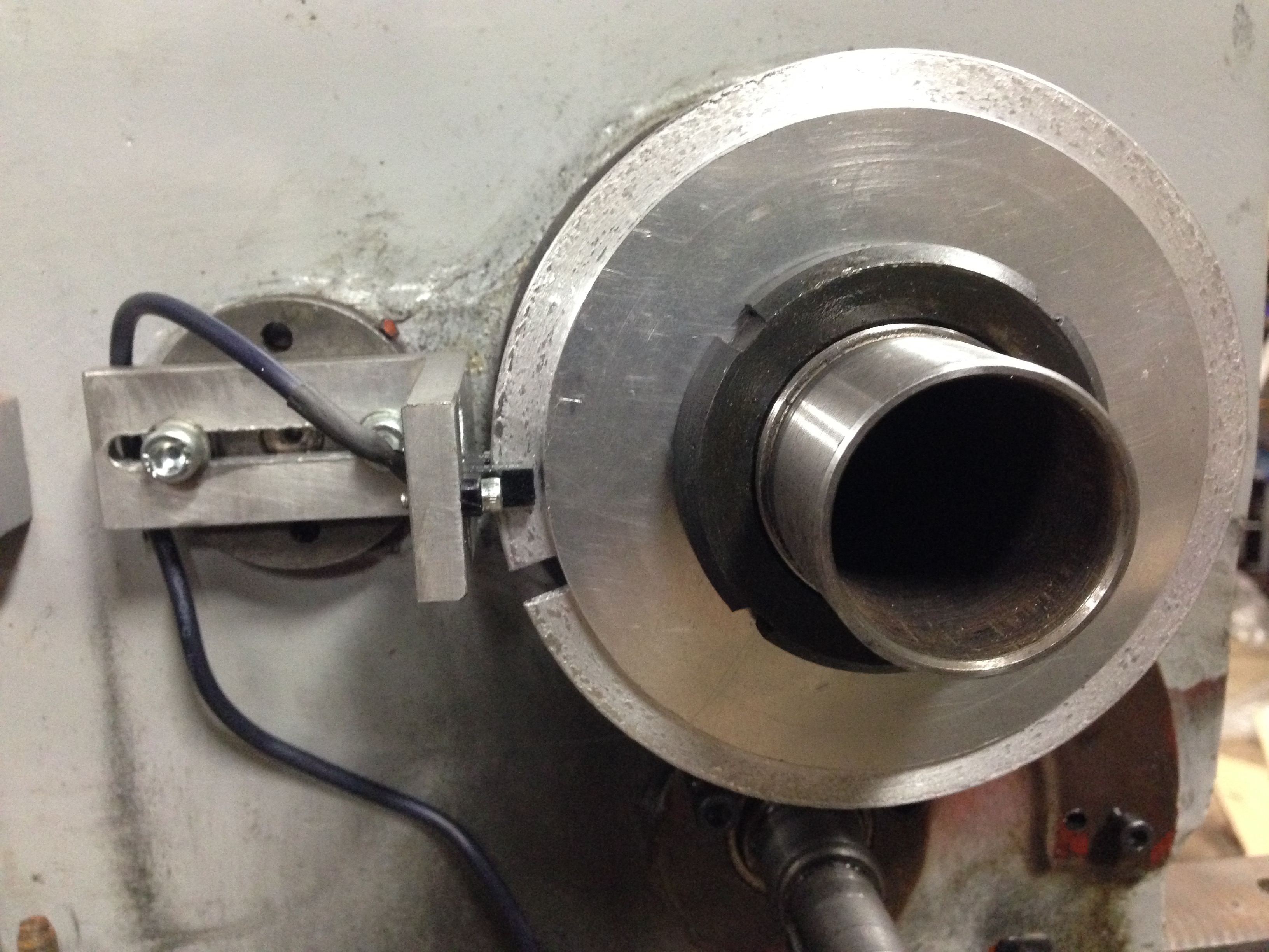
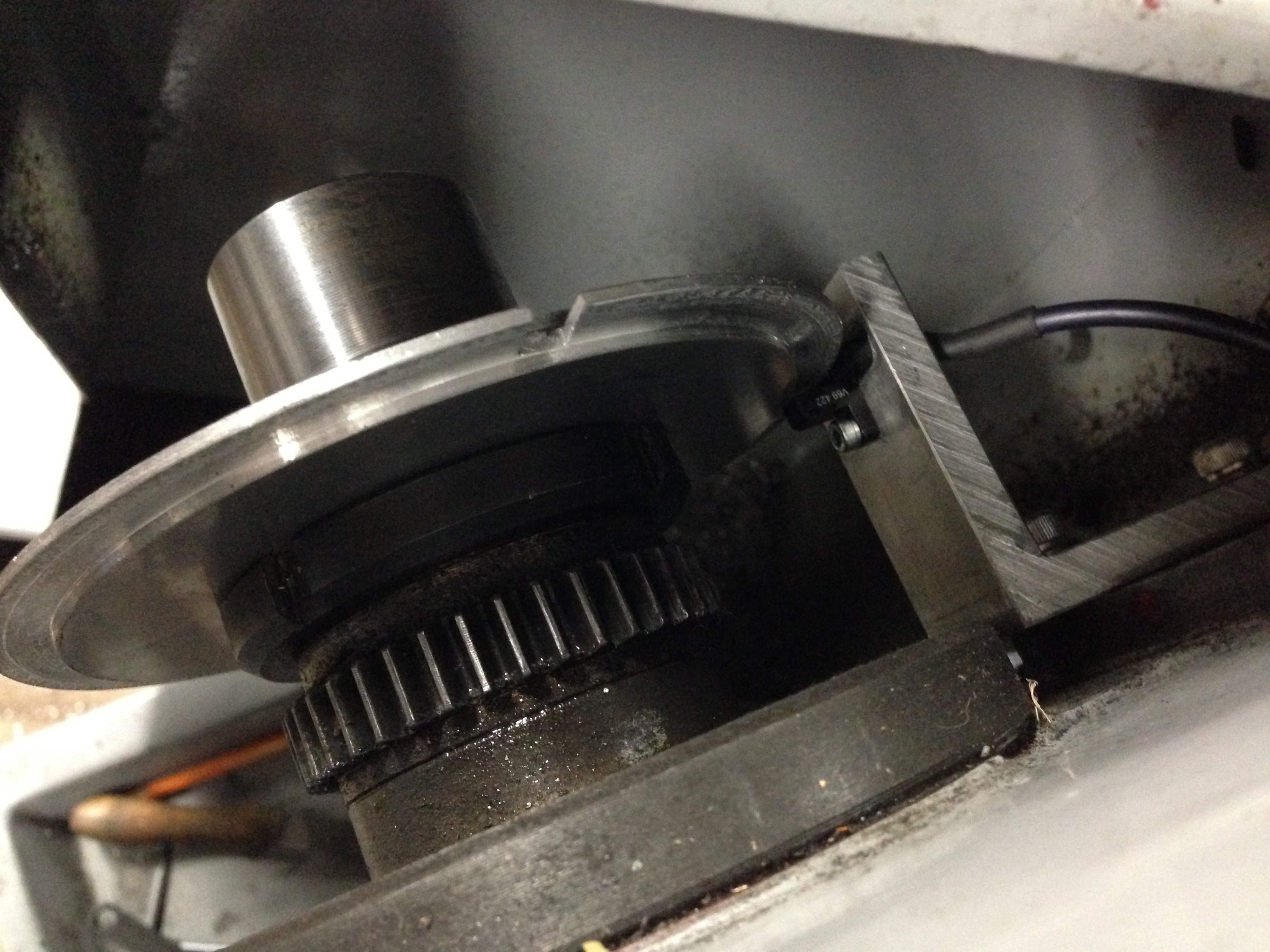
The latest was to make and install a spindle speed (and position – thanks David M) sensor. It consists of a disk with a slot cut in the periphery, attached to the main spindle. And an opto-electronic sensor which is connected to its own electronic board, thence to the breakout board and VSD.
The disc with the slot at 8:30 and the sensor at 9:00. I must have chosen the wrong cutter or turning speed for that disc aluminium… looks a bit rough. (note added 13/7 Stuart T says that I should have used coolant-lubricant).
View from above. Any clearer? That gear is now superfluous except as a spacer.
So there is one electronic impulse per spindle revolution. That is enough to measure the RPM’s. Essential for cutting threads.
The beauty of this system is that there is no gear selection or changing, and ANY thread pitch can be selected… metric, imperial, BA etc… any odd ball thread that your heart desires.
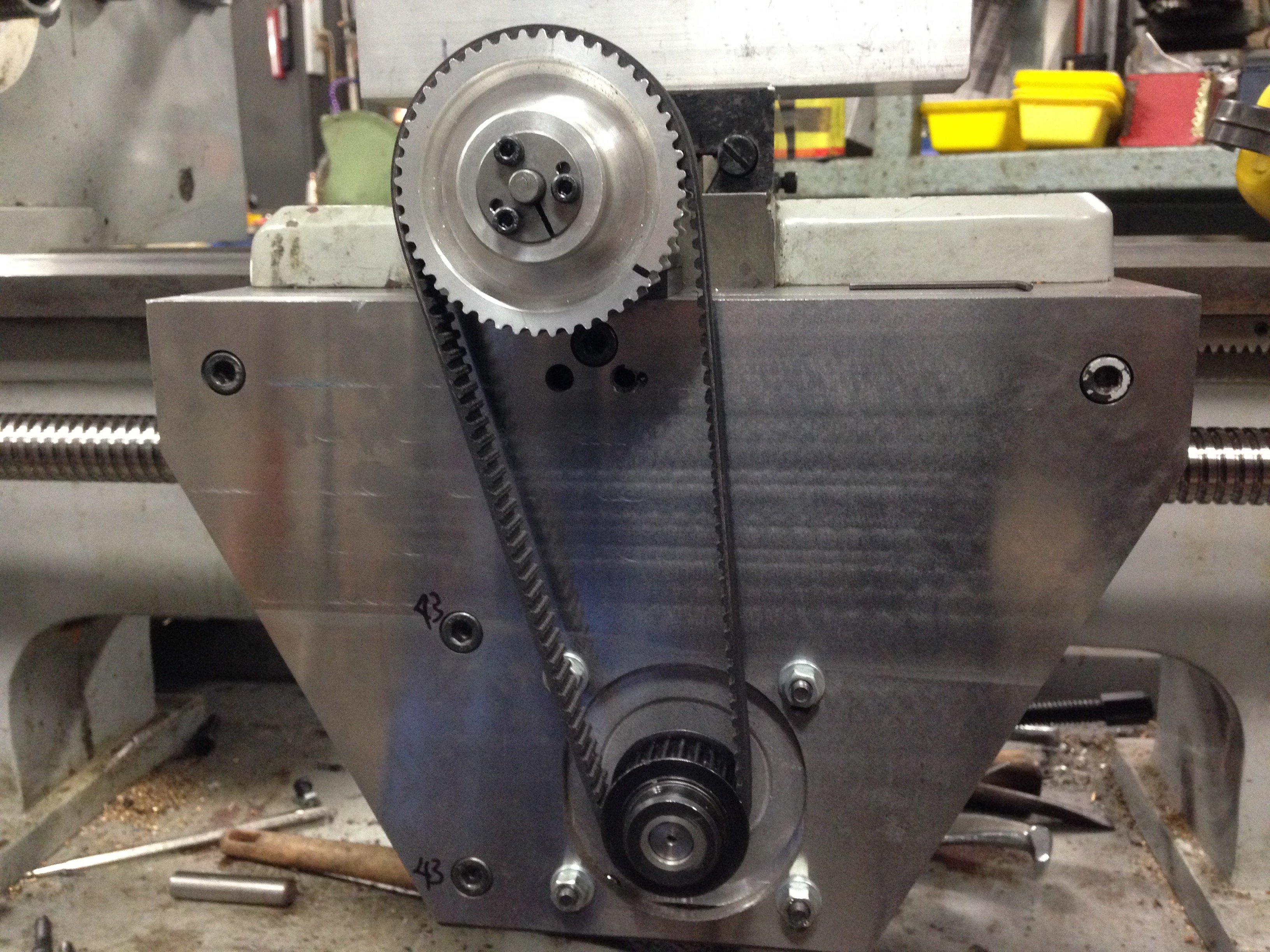
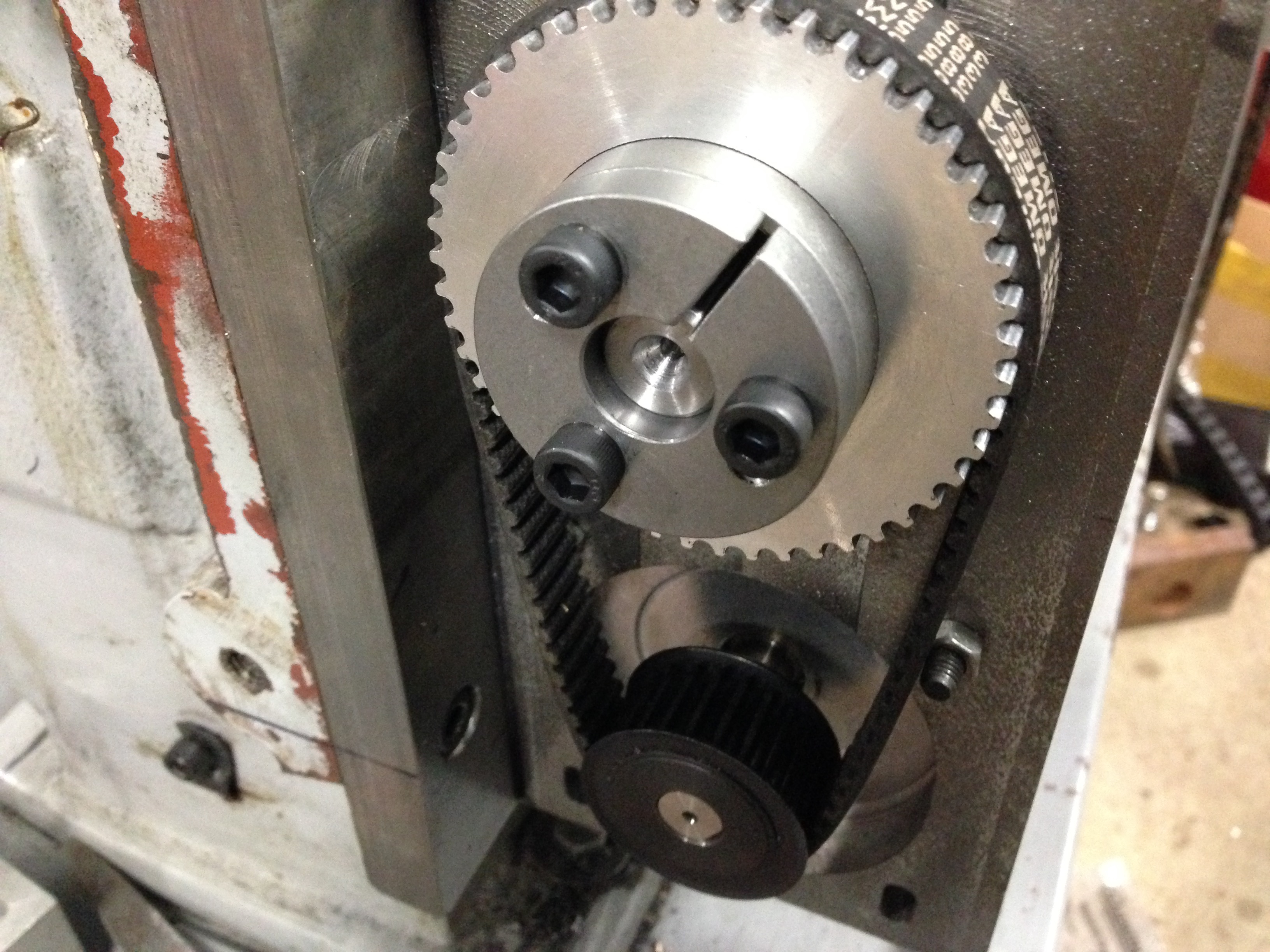
The HTD (high torque drive, I am informed by many readers) pulleys and belts and taper lock fittings. Unfortunately I could not find a taper lock to fit the small pulleys, so when it is all finally, definitely, absolutely, correctly, positioned, I will Loctite them in position. Protective covers yet to be made. I quite like to see the mechanicals in action, so I am intending to make the covers from clear polycarbonate.(Lexan) .
No big deal, I sense that you are thinking. After all, the ends are machined, the bearings fitted, and all waits in readiness.
True, but there is a strict sequence of events. And since it has been 3 or more weeks since it has been together, I had to rediscover the sequence, by trial and error. And each bit of the fitting is very heavy, very delicate, very tricky. So it took me several hours to get to the final photo in this blog.
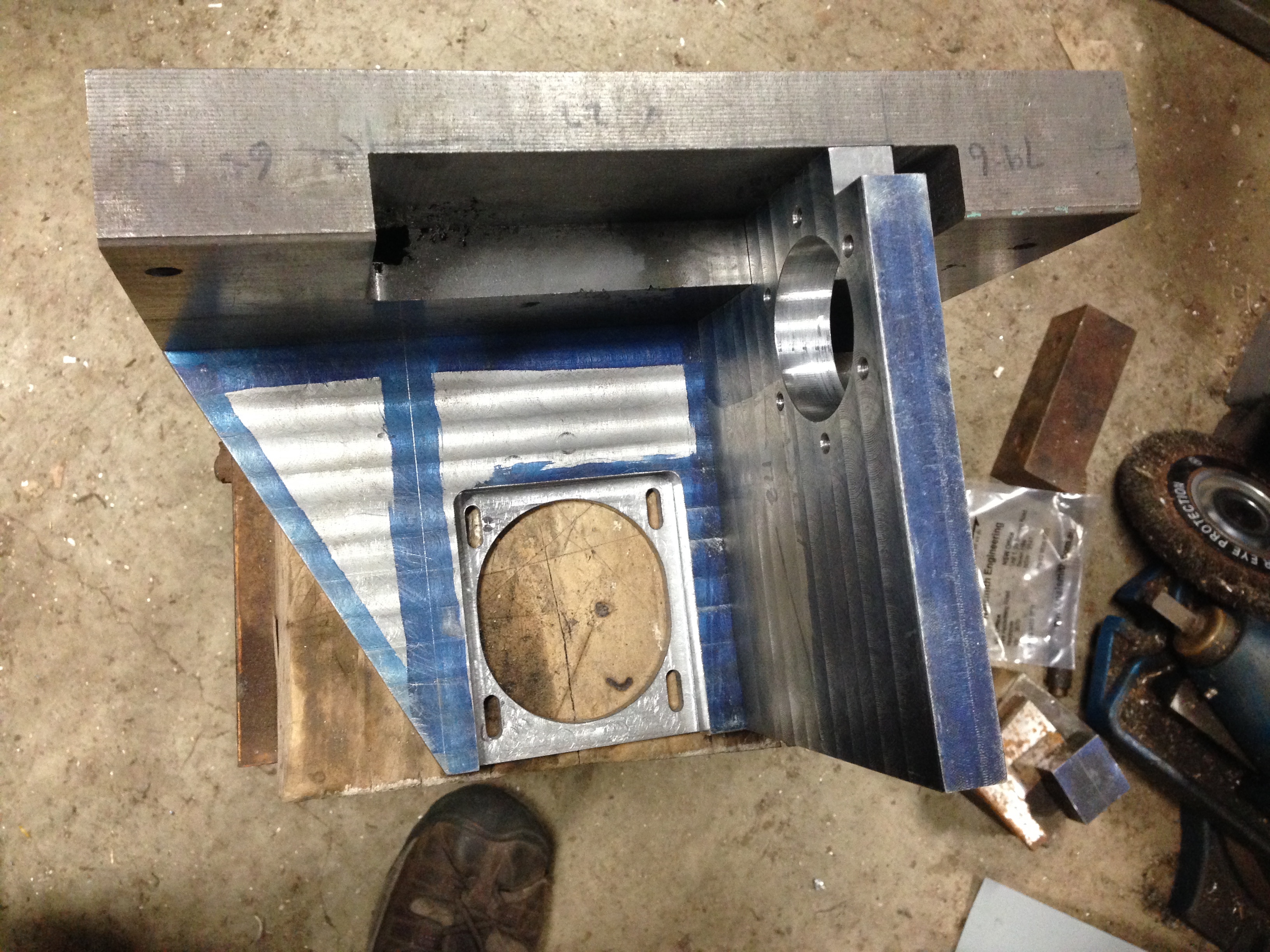
But first a view of the inside of the newly machined apron.
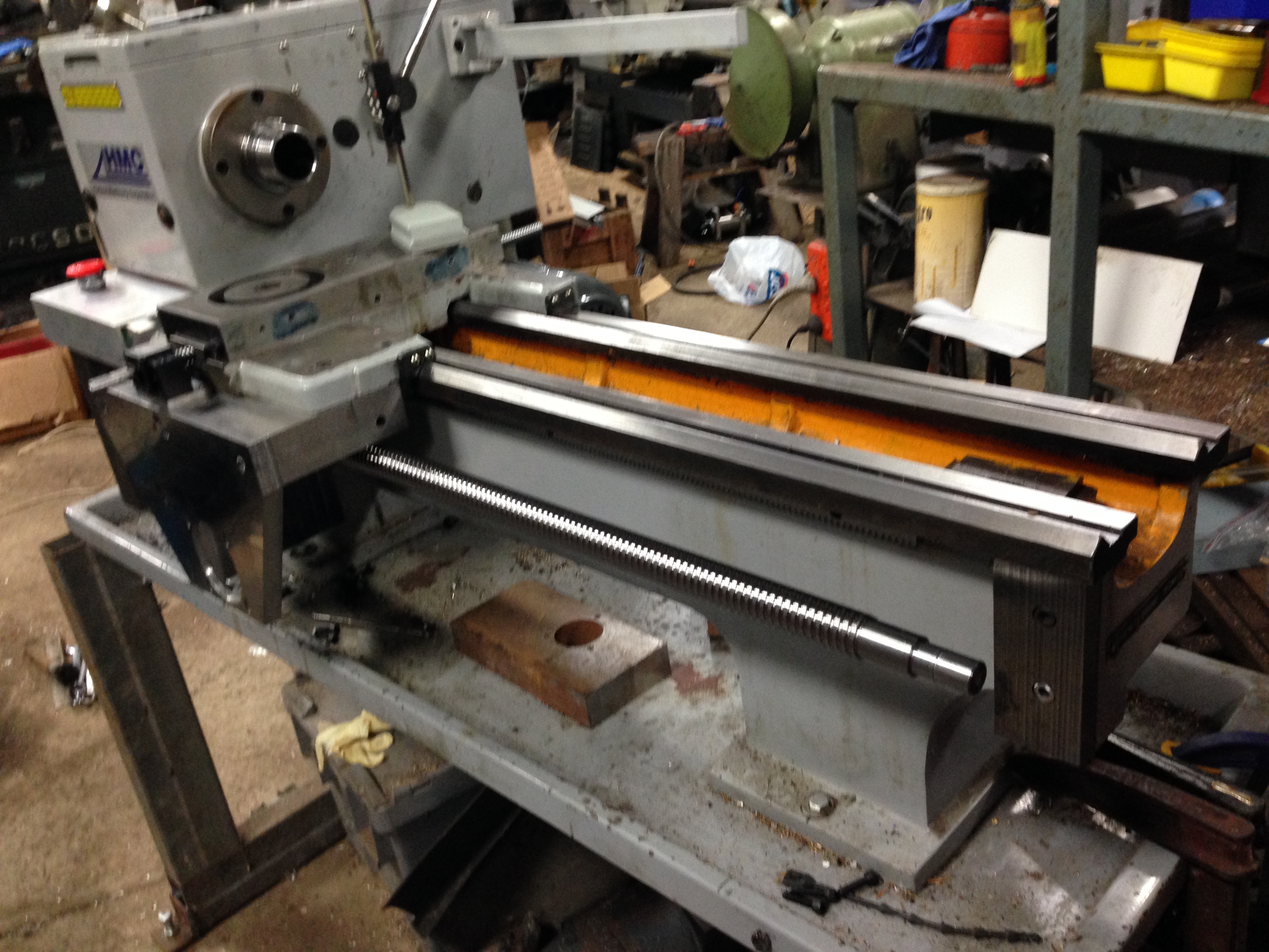
The lead screw fitted. The cross slide screw is also fitted. Note the red E Stop panic button fitted to the left. Next job is to fit a support bearing at the right hand end of the screw. Then to check and adjust parallelism of the screws. A rough check showed that they are within 0.25mm
Today I collected the lead screw after the ends were machined by Statewide Linear Bearings.
I decided to drive the 100km each way to pick it up, in preference to using a courier. I wanted to ensure that all of the small bits were there, and also just to make sure it was handled properly. Mostly freeway, listening to Dan Carlin on the Persian-Greek wars, so it was a pleasant way to have 3-4 hours to myself. (If you do not know about Dan Carlin, Google him and download an episode. If history at school had been like this, we would all be history addicts.)
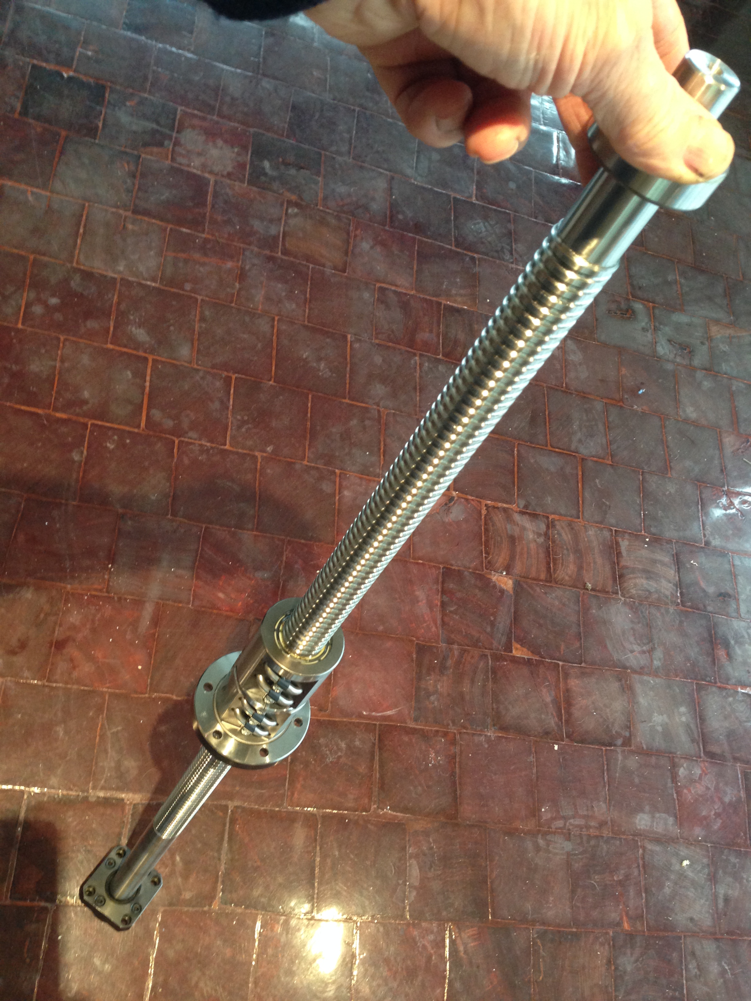
This is the lead screw, ends machined, and support bearings fitted. 1100mm long. 28mm dia
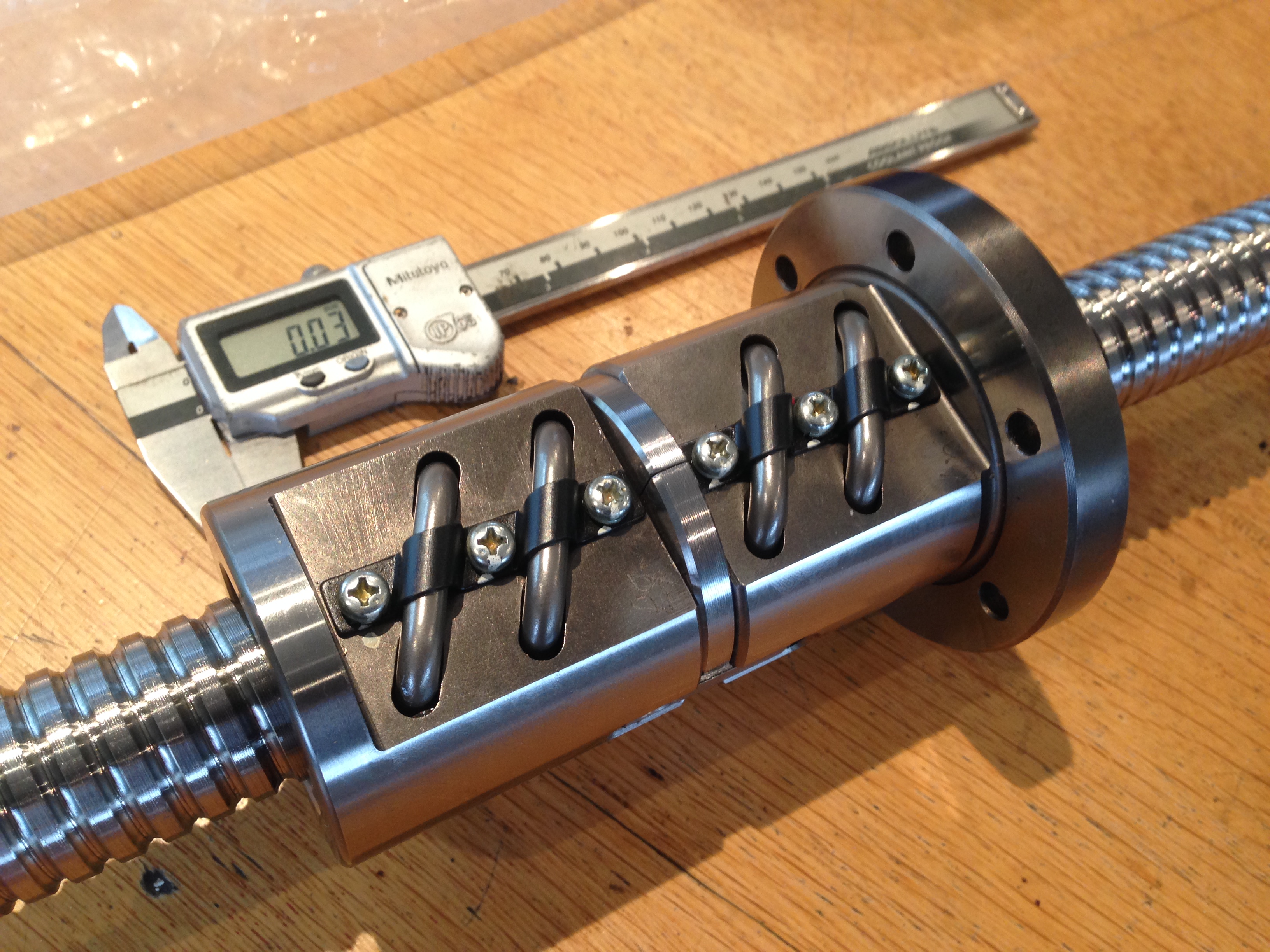
All good, except that the nut was back to front. That nut is pre-tensioned, which means that the 2 halves are separated by a precisely machined washer. I was nervous about removing it and replacing it the correct way around. However I had previously asked the ball screw expert about that aspect, so armed with the technique I made up a sleeve of the correct size, removed the nut and replaced it. No balls fell out. So all good! The above picture shows the nut in its correct position.
The nut. Looks expensive? Is expensive. And beautiful.
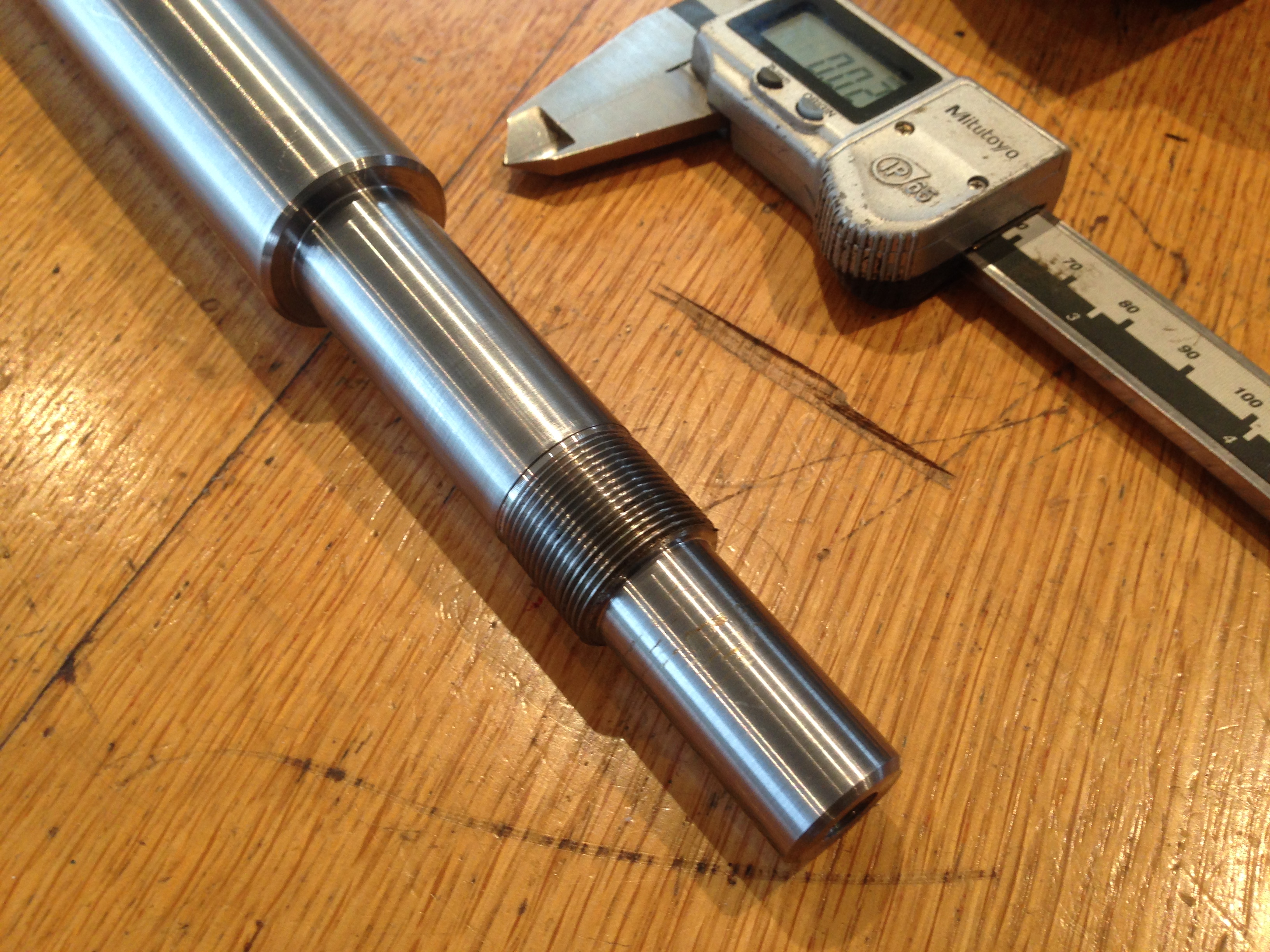
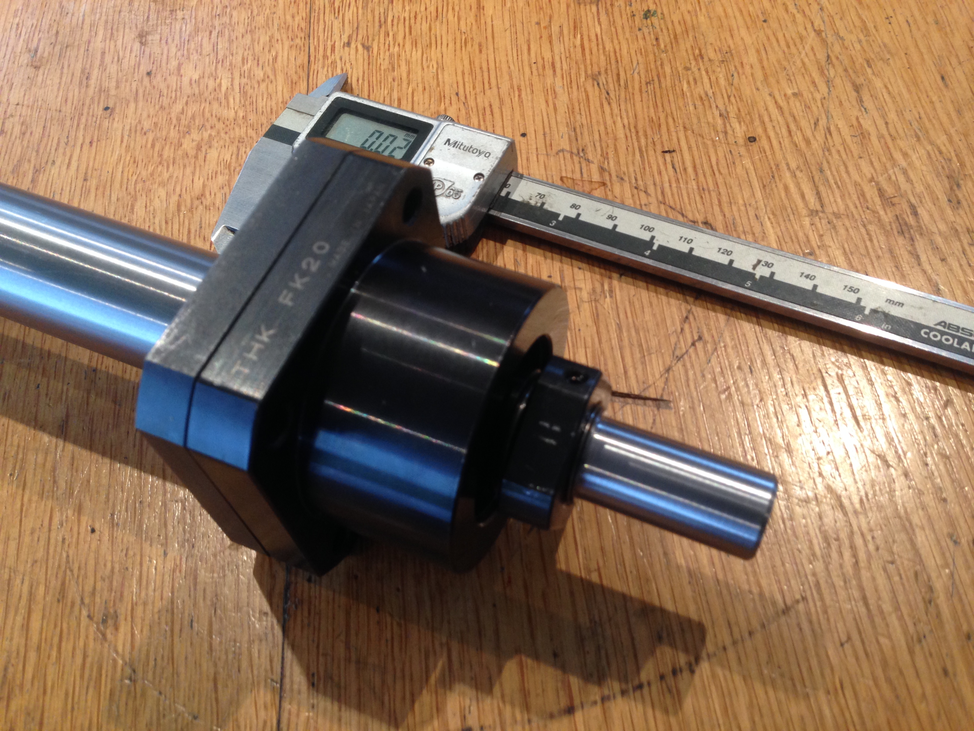
The machined driven end. $AUD250 machining there. But it is perfectly done.
And with the support bearing installed. A pulley for the HTD belt goes on the distal bit of shaft.