johnsmachines

machines which I have made, am making, or intend to make, and some other stuff. If you find this site interesting, please leave a comment. I read every comment and respond to most. n.b. There is a list of my first 800 posts in my post of 17 June 2021, titled "800 Posts"

Category: CNC

Smith’s Screw -3.

Another half day workshop session saw some more small parts made for the Smith’s Elevating Screw at ~1:10 scale. As close to 1:10 scale as possible, but I decided to make the parts about 20% bigger than the dimensions I scaled off the poor quality drawing, to fit with small drill bits and end mills in the tiny end of the range. The smallest end mill which I used was 1.5mm diameter!

CNC Drilling the gullets in the gear with a 1.6mm drill bit, after turning the OD of 15.9mm. I made 2 of these parts, just in case.

This is the gear after completing the gullets with the 1.5mm end mill. 3000rpm, 0.5mm depth of cut, 30mm/min feed rate. (metal working is not great for hand beauty)

The Smith’s Screw square thread, yet to have a hemispherical head turned after sawing off the excess length, the brass half cylinder nut, the gear, the yoke and the shaft bracket. A hinge pin will be inserted first, then some relieving of the hinge edges. The yoke and shaft bracket were CNC’d from 3.5mm brass plate.
and a handle to be added, and a restraining collar. Oh, and the 3 steel driving pins to be silver soldered in the yoke holes.

One more session should see the Smith’s Elevating Screw completed.

Did you notice that I have modified 6 details since drawing this?

Trunnion Mounts -3

I did not expect these mounts to require a third day session, and they are still not finished!

I discovered that two of the drilled holes in each bracket were in the wrong position, by approx 1mm.  That is a really bothersome error, because the correct position includes half of the existing hole.

I managed the problem by threading the errant holes, and Loctite gluing in some threaded rod.  Each rod was trimmed flush with the surfaces.   Then drilling the new hole, partly through the Loctited metal patch.  That fix worked well.

P1074281

Threaded rod glued into the errant hole.  Trimmed flush later.  Then redrilled correctly.


THE TRUNNION PINS.

The pins hold the trunnion caps in place.  And they took another whole day to make and install.   Ah….  just as well I enjoy all of this.  They are tiny, and I spent at least 50% of the time looking for them on the workshop floor after accidentally dropping them on several occasions.

P1074299

Milling the pin handles from 2mm steel.  The handles ended up at 7mm long.  The holes were drilled before the outlines were cut.  Then the tabs were ground off using my newly made belt sander belt.  The belt lasted 15 minutes before the belt itself tore, with the join still intact!

P1074308

Then some delicate silver soldering of a ring to attach a securing chain later, then the pin shaft itself.  The wire through the ring is just to hold it in position during soldering.

P1074309

And that is one of the 8 pins made.  I will polish them in a gemstone tumbler next session.

P1074310

On the model, the pins are jammed into position with a cam action, after some filing-shaping.  On the original cannon there was a small protrusion on the inner end of the pin shaft, which fitted through a slot in the side of the carriage.  I could not figure out a method of making such a tiny slot (1mm wide x 1mm deep) through 4mm of steel plus 2mm of brass, but the cam action seems effective.    I will attach some chain soon, because I do not wish to make any more of these.  And yes, the pins handles are slightly over-scaled, but I think not outlandishly so.

So, apart from polishing riveting and painting, I think that the trunnion mounts are finished.

Now planning to make the gear train for the carriage positioning on the chassis, and the pinion, quadrant gear, and bevel gears for the barrel elevation.  We are currently in level 3 lockdown for Covid containment, with level 4 looking likely any day, so obtaining brass for the biggest gears is difficult.  I am considering workarounds.  Apparently community anxiety and depression, family violence, and even suicides are mounting.  When I am in the workshop I am in a different world, thank goodness.


91 x 4 drilled holes. Yes, counting.

Today I drilled the girders of the chassis under the Armstrong cannon.  Each girder has 91 rivet holes.  Later I will need to drill more for the gear shafts, and for the center pivot bar.

The holes are 2mm diameter.

PANA3767

The mill drill setup. Re- indicating the vices again took me about 45″.

PANA3769

Firstly all of the holes were center drilled, then drilled through.  The rivet confirmed a nice sliding fit.

PANA3770

364 holes, through 5mm of steel done with one center drill, and one 2mm drill.  That is pretty impressive IMO.  More than 1.8 meters of steel with 2 drill bits.  And using my olive oil and kerosene lubricant-coolant.   And the bits still seem to be sharp.

Each girder took about 28″ to drill the 91 holes.   CNC of course.  It has been a while since I said it….. “I love CNC”.


Bronze Casting -2

When I looked closely at the rifling cutters which I had lasered out of a broken Brobo saw blade, I realised that I had boobooed.  I had measured the thickness of the blade at 2.5mm, which was actually a bit thinner than I wanted, but would have been acceptable. But when I measured the cutters, they were only 2.2mm thick.   Reason?  The saw blade had been hollow ground, and the blade inside the teeth was thinner.   Too thin, I decided.

So after some wailing and teeth gnashing I have ordered some 3mm thick tool steel in the form of planer blades, which I am pretty sure will not be hollow ground, and I will ask the laser cutter to cut me some more blades.  So waiting waiting.

And I am setting up the cannon barrel for rifling.  The CNC rotary table (stepper motor hidden behind) will be bolted to the CNC mill table.  The barrel is held in the jig which is held by the mill quill.  The cutter, (not seen in this photo) will be drawn out of the barrel by the mill X axis, while being rotated in the A axis by the rotary table.   That is the plan anyway.  But still waiting for bits to arrive so I can finish the cutting tool.

P1053658

The Armstrong cannon barrel held to the mill quill, and the rifling cutter will be held by the CNC rotary table.

IMG_8537

The rifling tool which I will not be using because the cutter is too narrow.  The cutting edge just peeping out of the slot will be dragged and twisted through the barrel bore.  The cap screw adjusts the degree of protrusion.


BRONZE CASTING

Meanwhile, I am accumulating various bits of gear to do some bronze casting.   An electric furnace with graphite crucible from China, Some jewellery investment material for the moulds, and a second hand pottery kiln for preparation of the moulds, and melting out the PLA 3D printed parts.   I will take some photos when it is all here.

And SWMBO has conscripted me to assemble and install some kitchen cupboards for a property which she is renovating.

P1053684

P1053685

These are flat pack units.  Kaboodle.  Well designed and CNC cut and predrilled.  Not quite finished.  Waiting for the stone bench tops to be made and installed, and for appliances to be wired and plumbed.  Frankly I would prefer to be tidying up my workshop, but hopefully I am gaining some “Brownie Points”.

NBN. At Last!

And about the last.  The fibre optic network was commenced about 3 years ago, and I applied for a connection shortly after.

Despite living in the centre of Victoria’s second biggest city, my house was not connected to the National Broadband Network until today.

Until then I have coped with download speeds as low as 1mb/sec, and uploads as slow as 60kb/sec.  Do you wonder why I upload so few videos?

Today, the NBN was finally connected.  The download speed is a blistering 50mb/sec, and uploads 25mb/sec.  Wow!

Just to celebrate, I am posting some pictures.  Not much to report from the workshop, but I am accumulating some items in readiness for rifling the model cannon bore.

P1053654

This photograph would typically have taken 60-120 seconds to upload previously.  Today it took about 5 seconds!    As you can see it is a cold saw blade which has seen better days.  My bad, unfortunately.   But I saved the pieces,  because these blades are made of high quality tool steel.  I have had some parts laser cut .

P1053653

The laser cutter left the tabs intact so the tiny parts would not be lost.

P1053655

The 2.5mm thick part popped out with a bit of finger pressure.  Not much tidying up required here, but I will sharpen the cutting edge.  This will be the cutter for the rifling of the model cannon.

This is the first time I have had parts laser cut, and I am impressed by the accuracy and smoothness of the cut and the narrow kerf (0.2mm).    Oh, and the cost.  It was surprisingly inexpensive.  ($AUD26).


3D Printing is SLOW

P1053454.JPG

Crealty CR-10s 3D printer.  The machinists parallels were my solution to ensuring that the horizontal arm is parallel to the base frame.

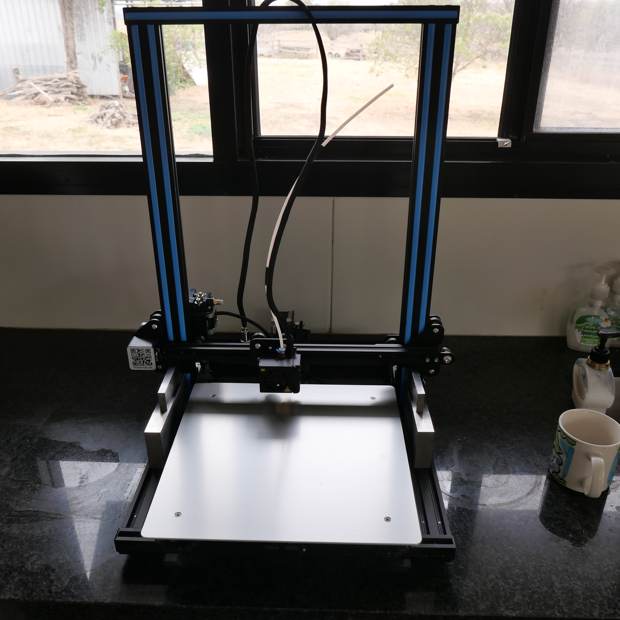
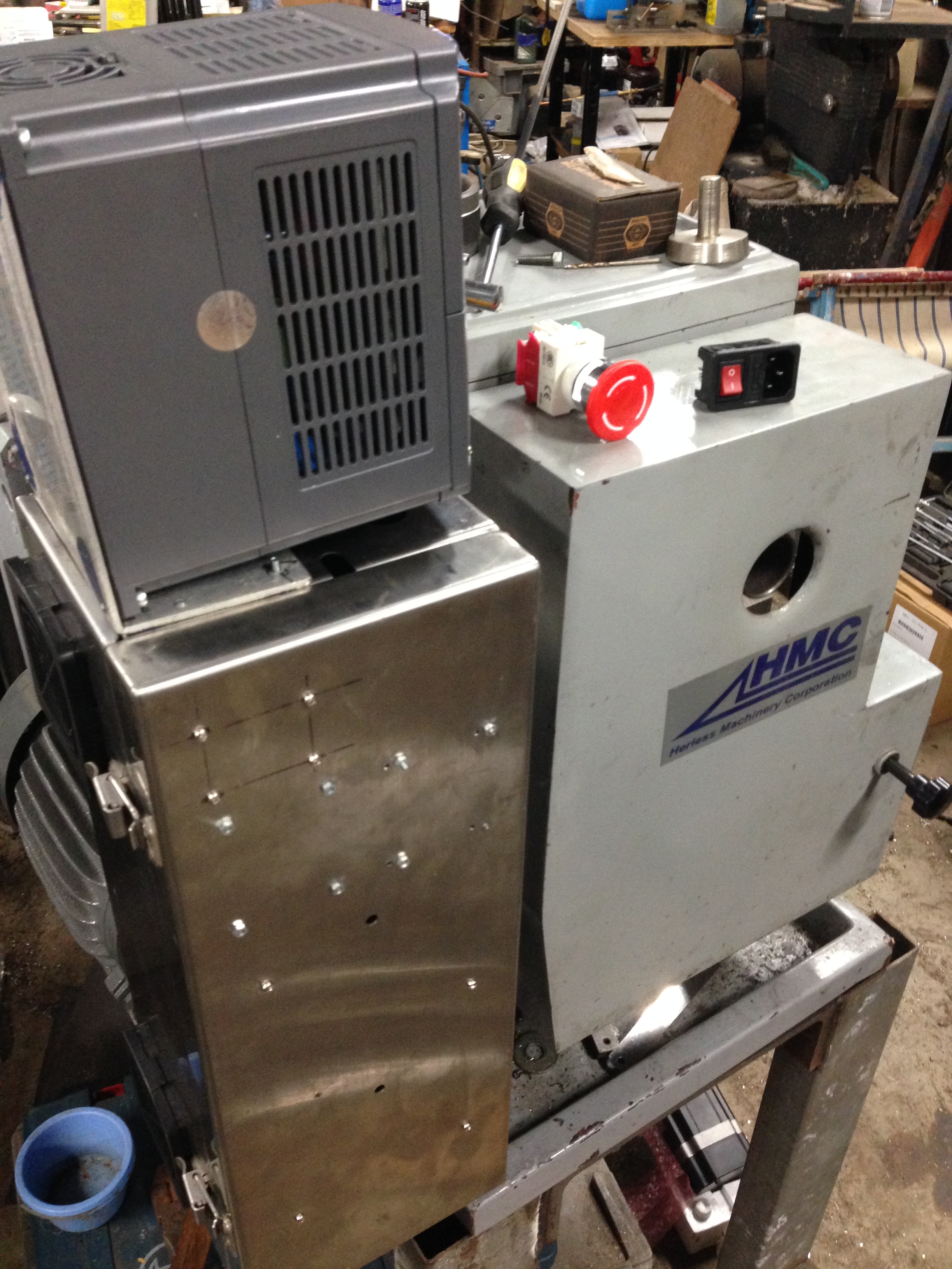
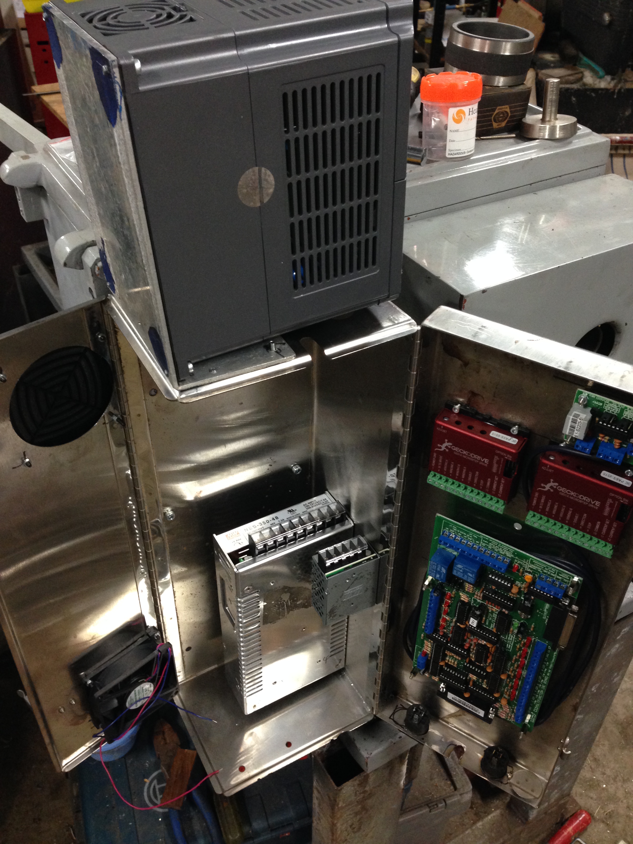
So, I took delivery of the 14kg box, and spent a couple of hours assembling the printer.  It was partly assembled, as delivered, and if I had known what I was doing the final assembly would have been done in a fraction of the time.  The assembly instructions were adequate.  The wiring connections were well labelled.  The wiring connectors were delicate, and I took care not to bend or break them.

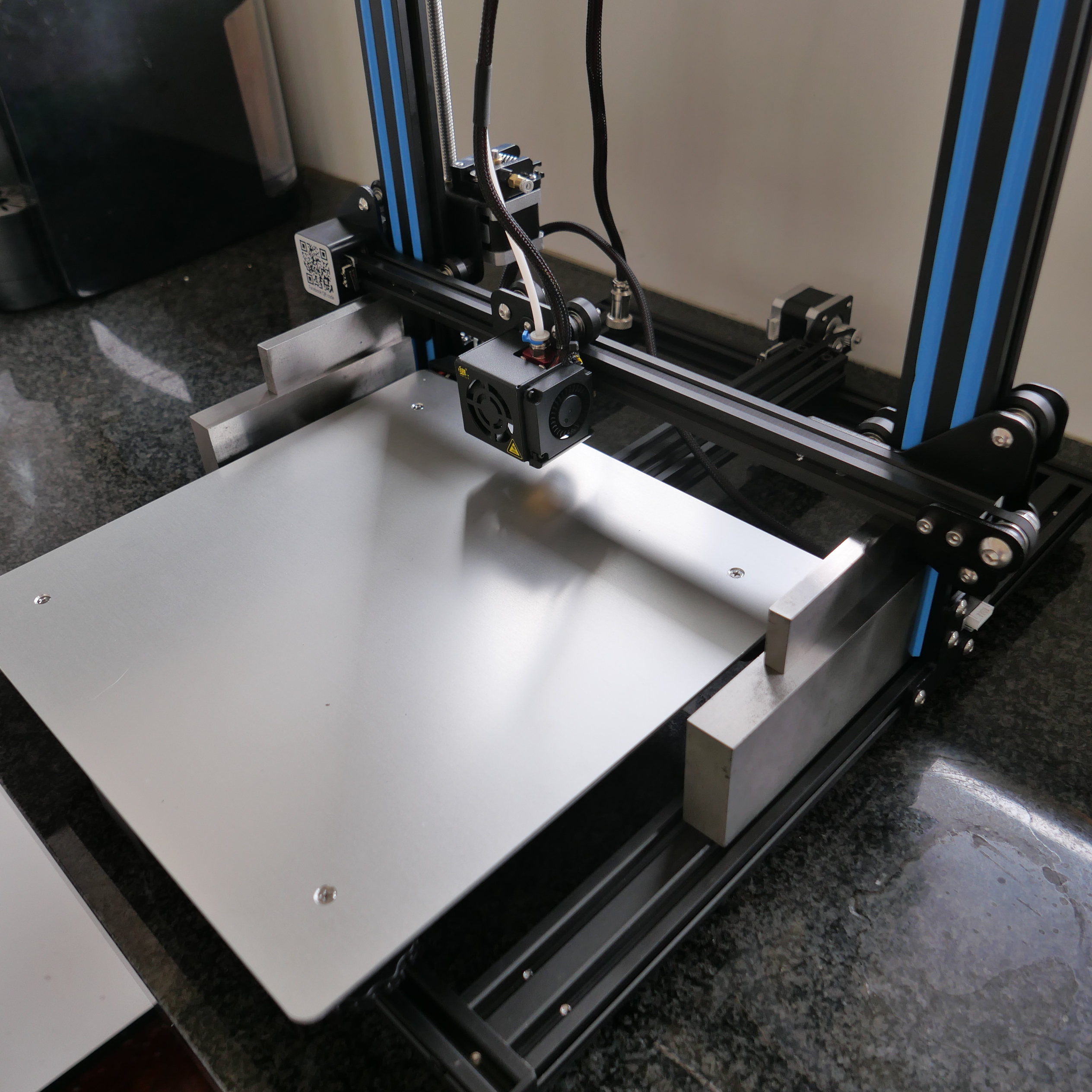
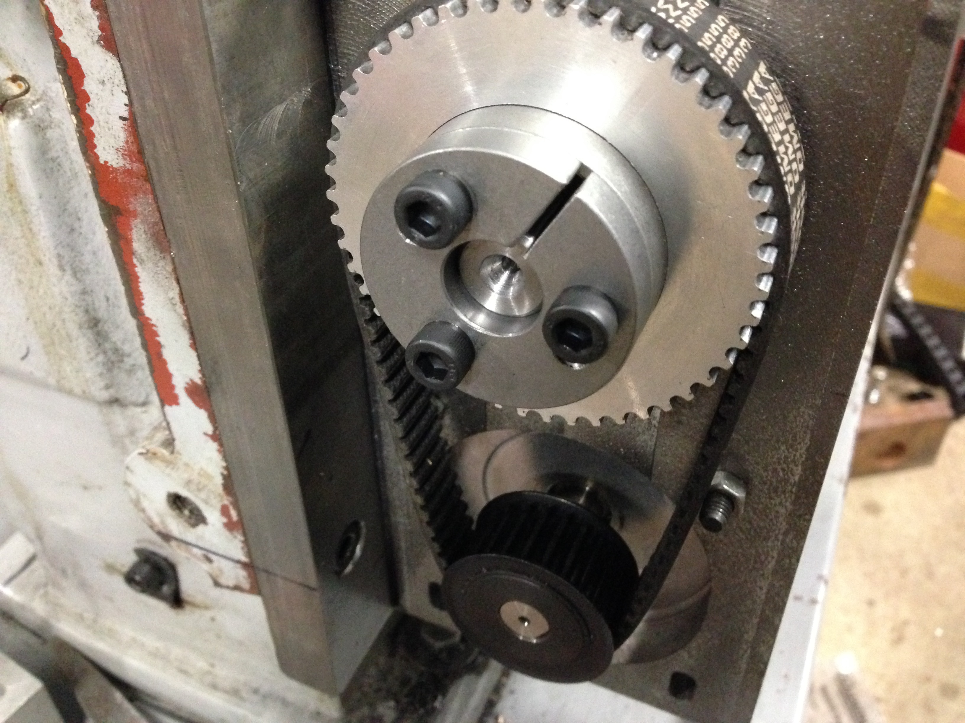
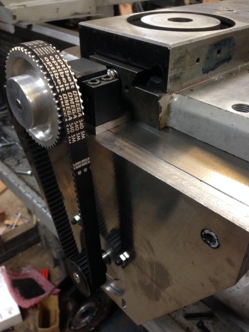
The vertical frame bolts to the base frame, and it is surprisingly rigid.  There are 2 Z axis stepper motors, and when not powered up, they can be individually turned.  It occurred to me that the horizontal arm which the Z axis motors raise and lower should be exactly parallel to the base, so I placed the machinist’s parallels as shown in the above photo and screwed the horizontal arm down onto the parallels to set the horizontal position.  I assume that the Z steppers will move the arm equally. (Hmm… I will check that assumption later.)

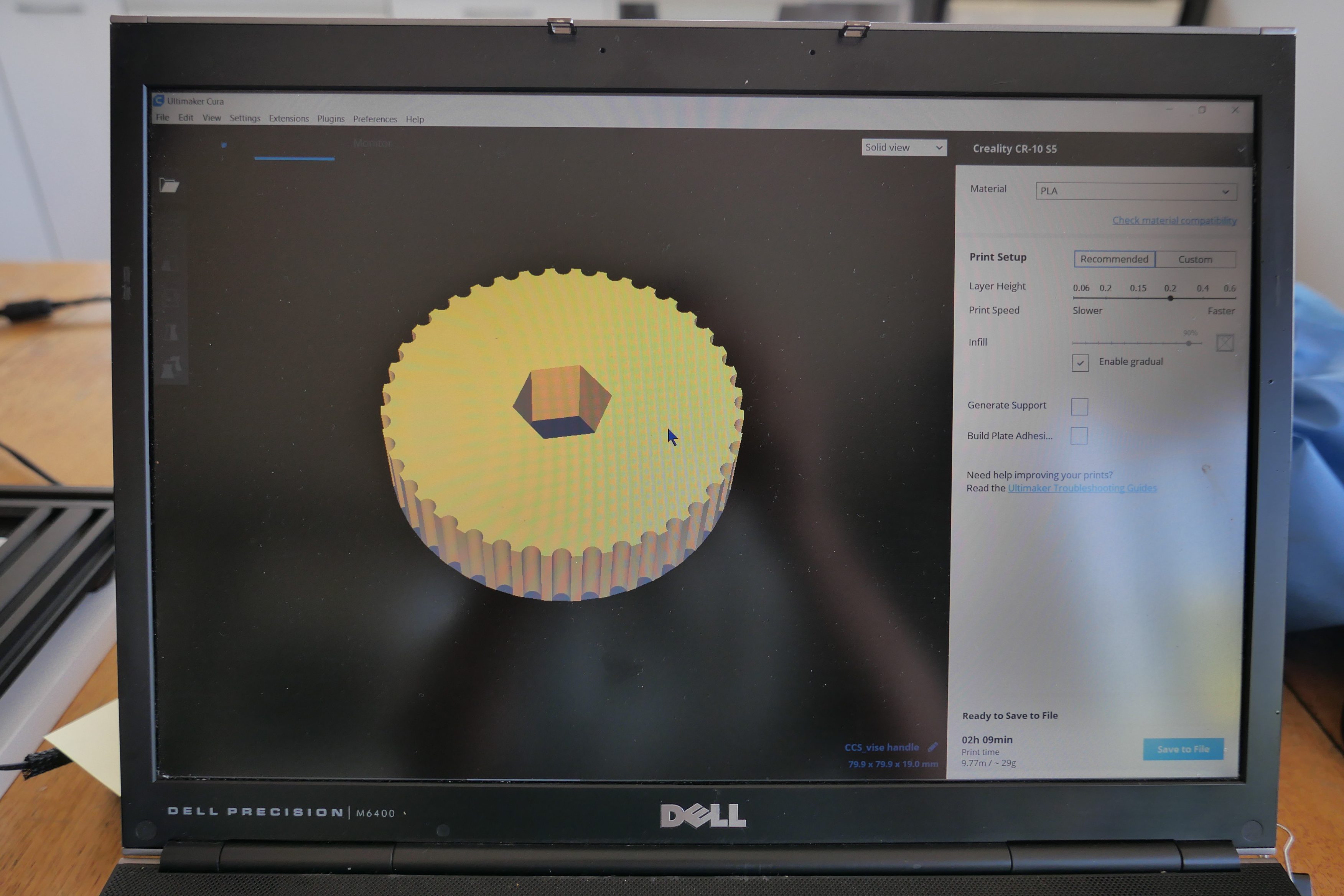
Next day, I downloaded the operating software.  An older version was supplied with the machine, and the newer version would not work on my old XP Pro Windows computer, so I used the old version.

I spent some time manually levelling the bed, then ran the automatic bed levelling software.

The printed operating instructions are very basic.  An Internet connection is assumed, and I did not have one available, so my first printed object was with default settings and the supplied white filament.

Somewhat to my surprise, it worked.

P1053455.JPG

The platten is aluminium.  A glass plate was also supplied, so I used that on top of the aluminium.

The filename was “dog”.  I had no idea whether “dog” was a 3D dog, a picture, or whatever.  Neither did I have any idea of its size.  After an hour, I had printed a disk about 125mm diameter and 1.1mm thick.  Then the disk came off the platten, so I aborted the print.

Today, after getting some advice from Stuart T regarding print adhesion I removed the glass platten cover and applied some special adhesive 3D printer cover.  It is called “3M double coated tissue tape 9080A”.  Then I printed 2 more items.  Neither broke free.  in fact they were difficult to remove at the conclusion of the prints.

P1053466.JPG

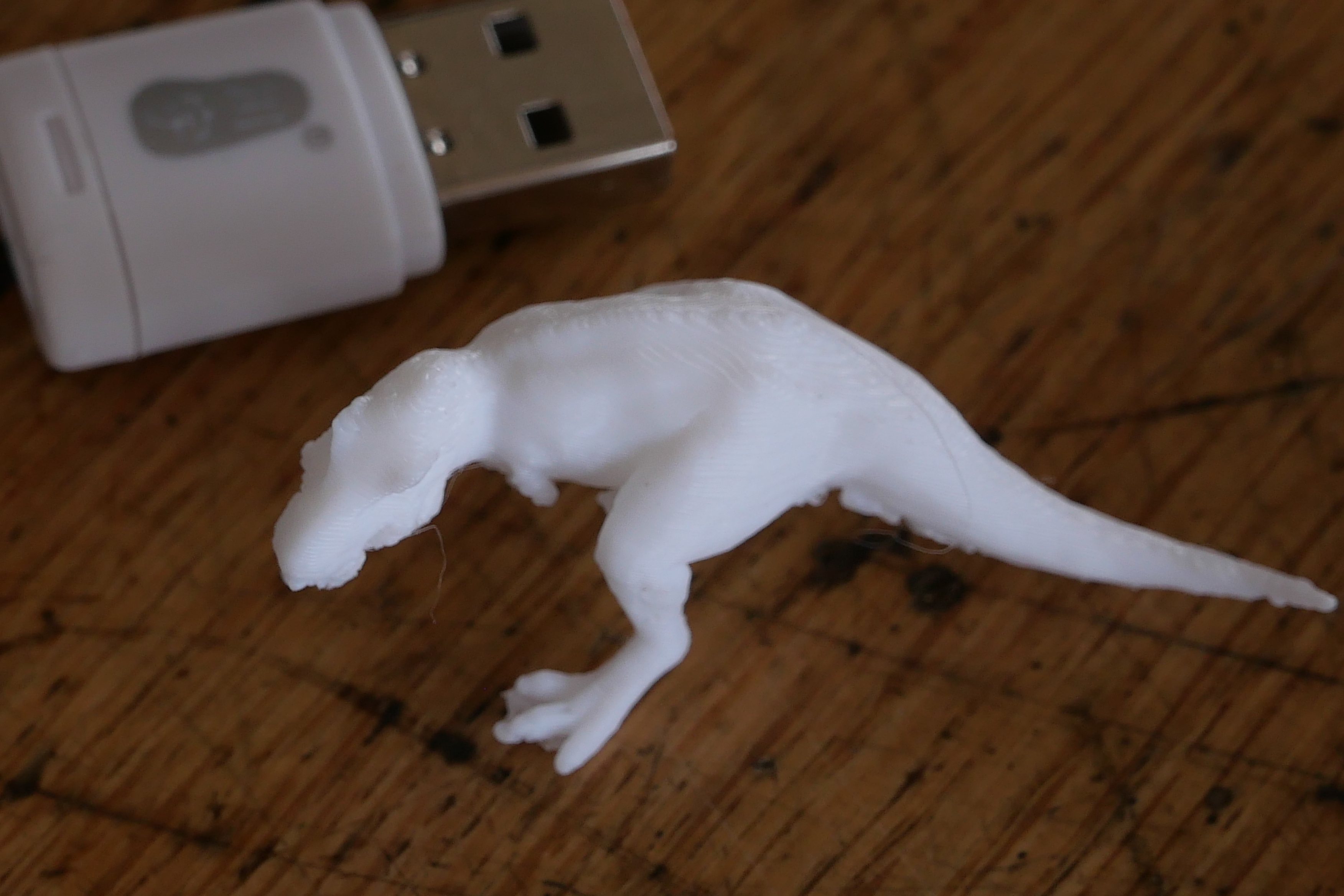
This tiny Tyranosaurus was printed from a 3D file which I found on my computer.  It printed in about 20 minutes.  Default settings again.  The supports were too big for the object, and when I broke them free I also broke off the T Rex arms.  Some settings for supports need to be changed.

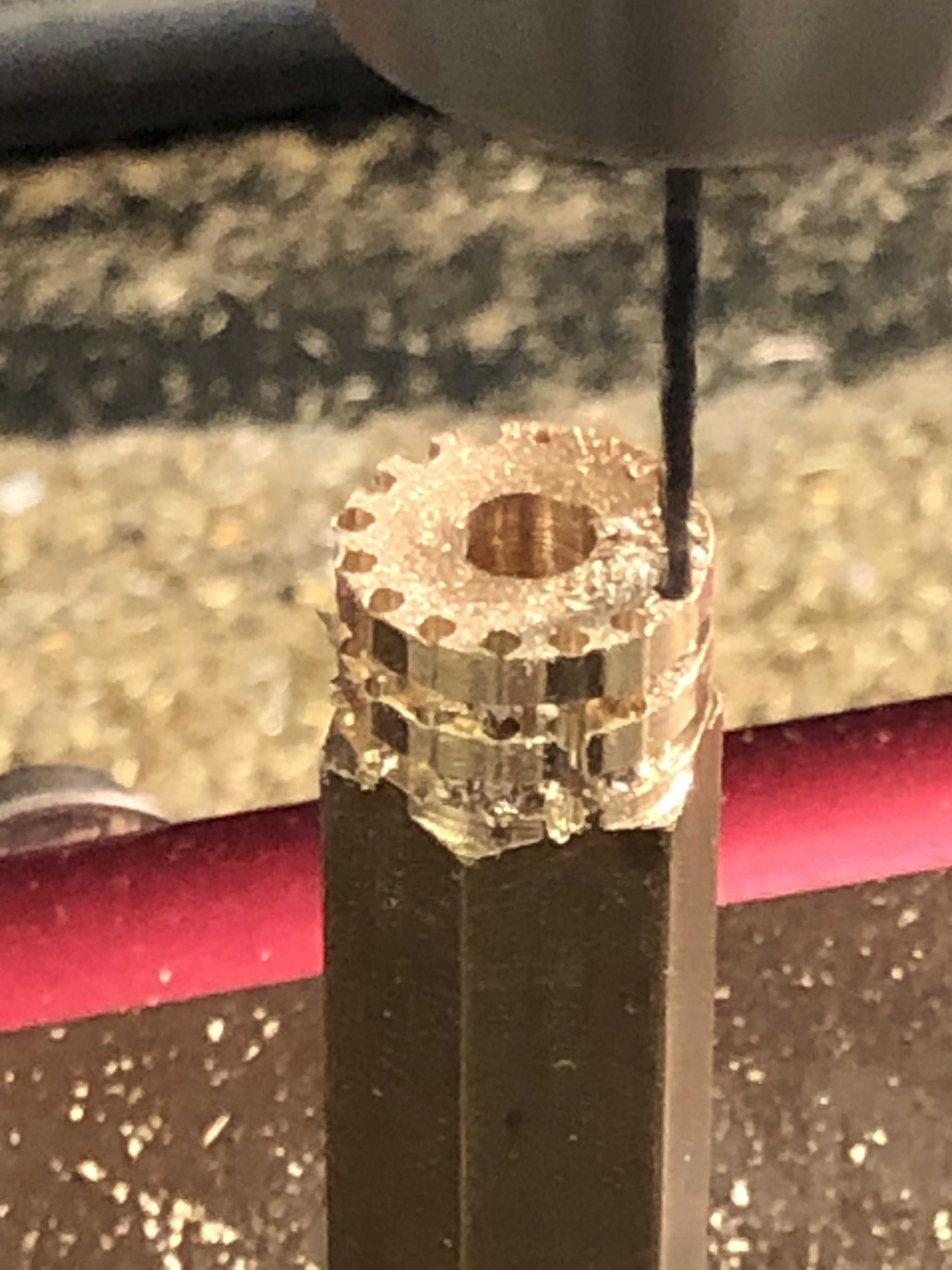
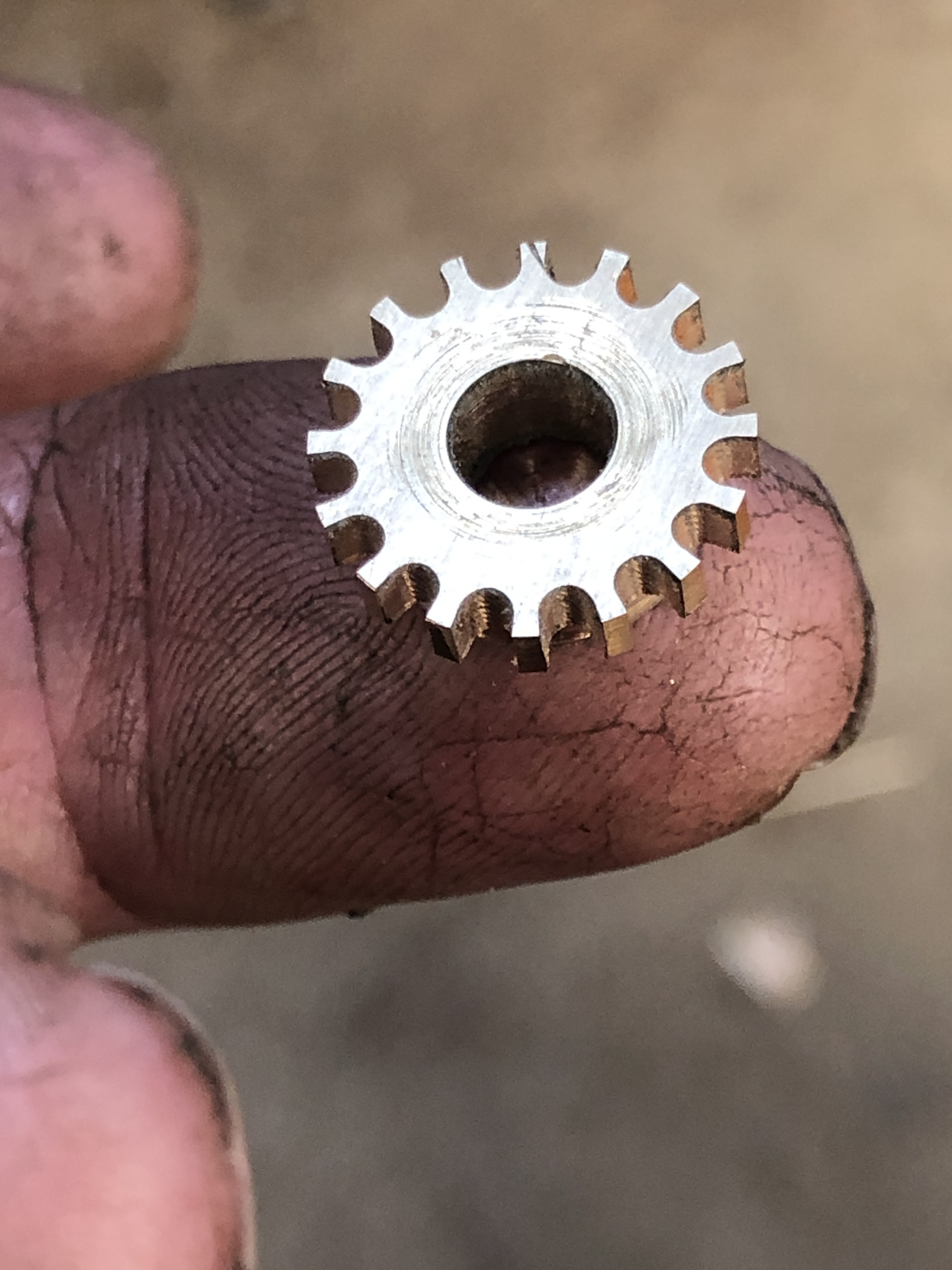
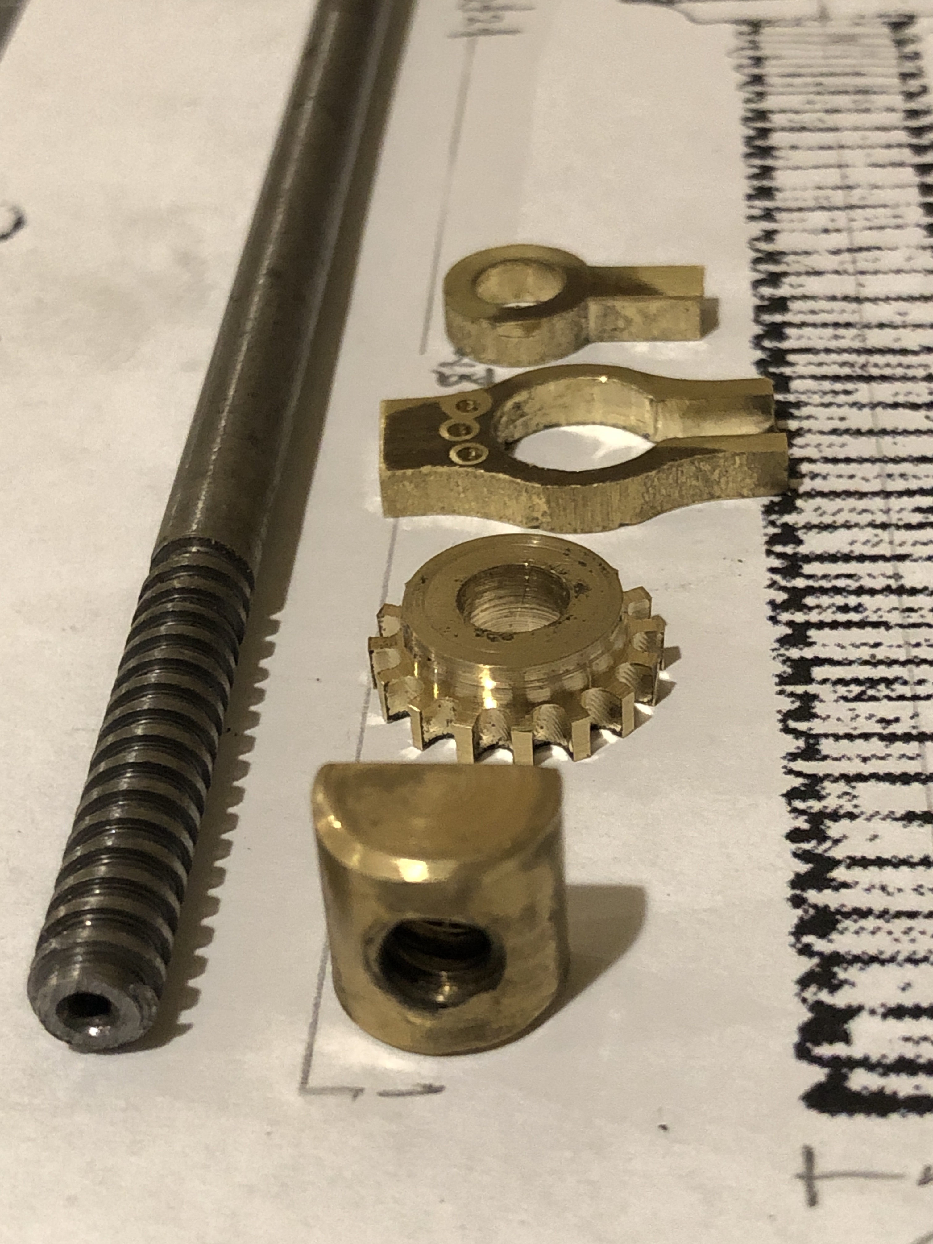
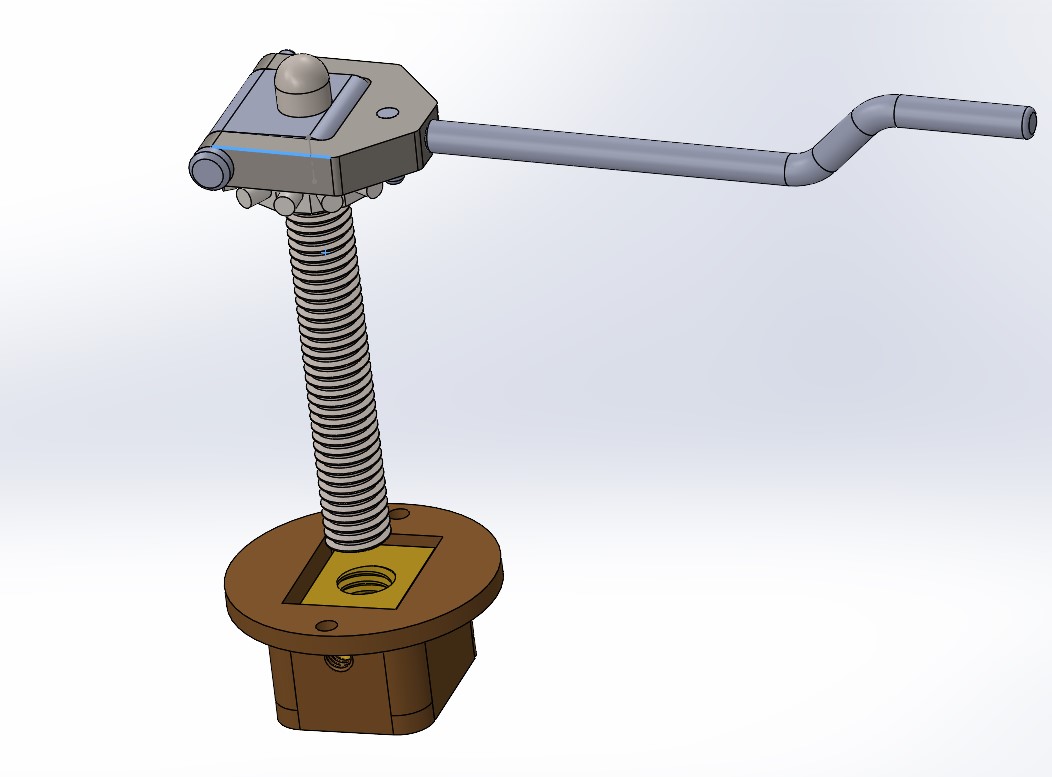
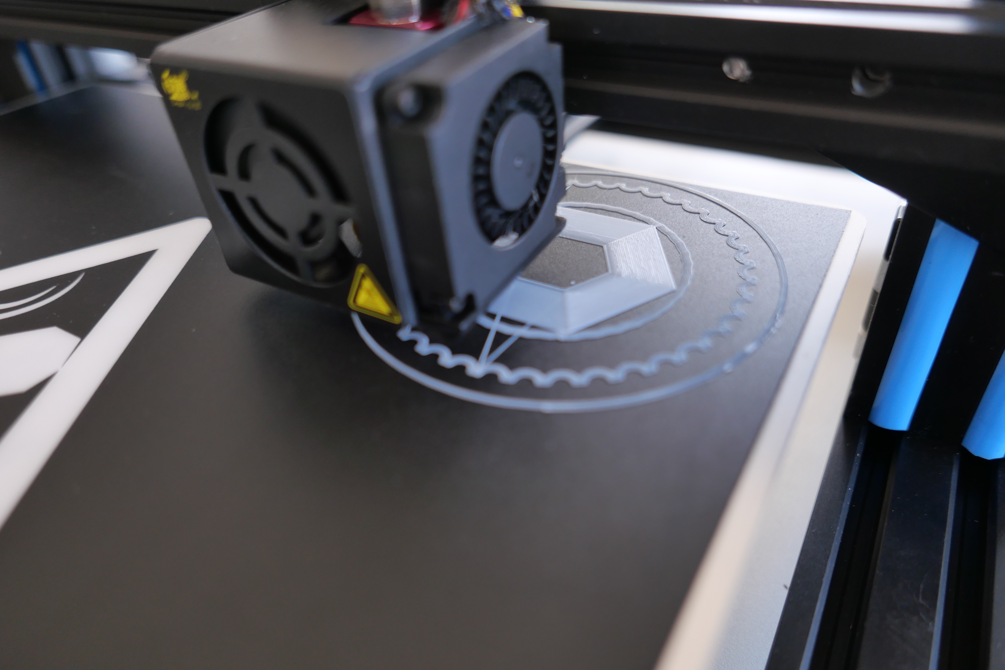
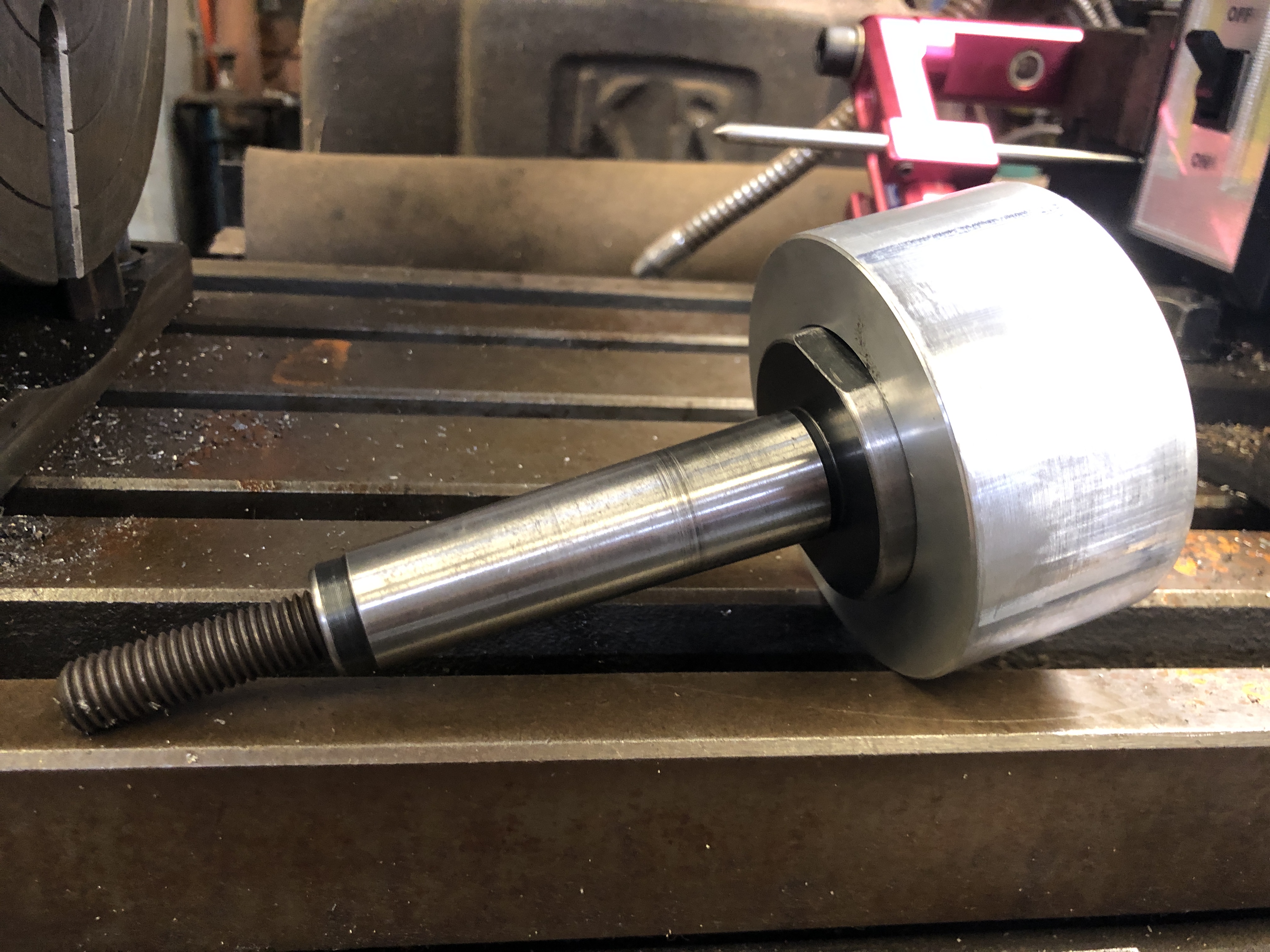
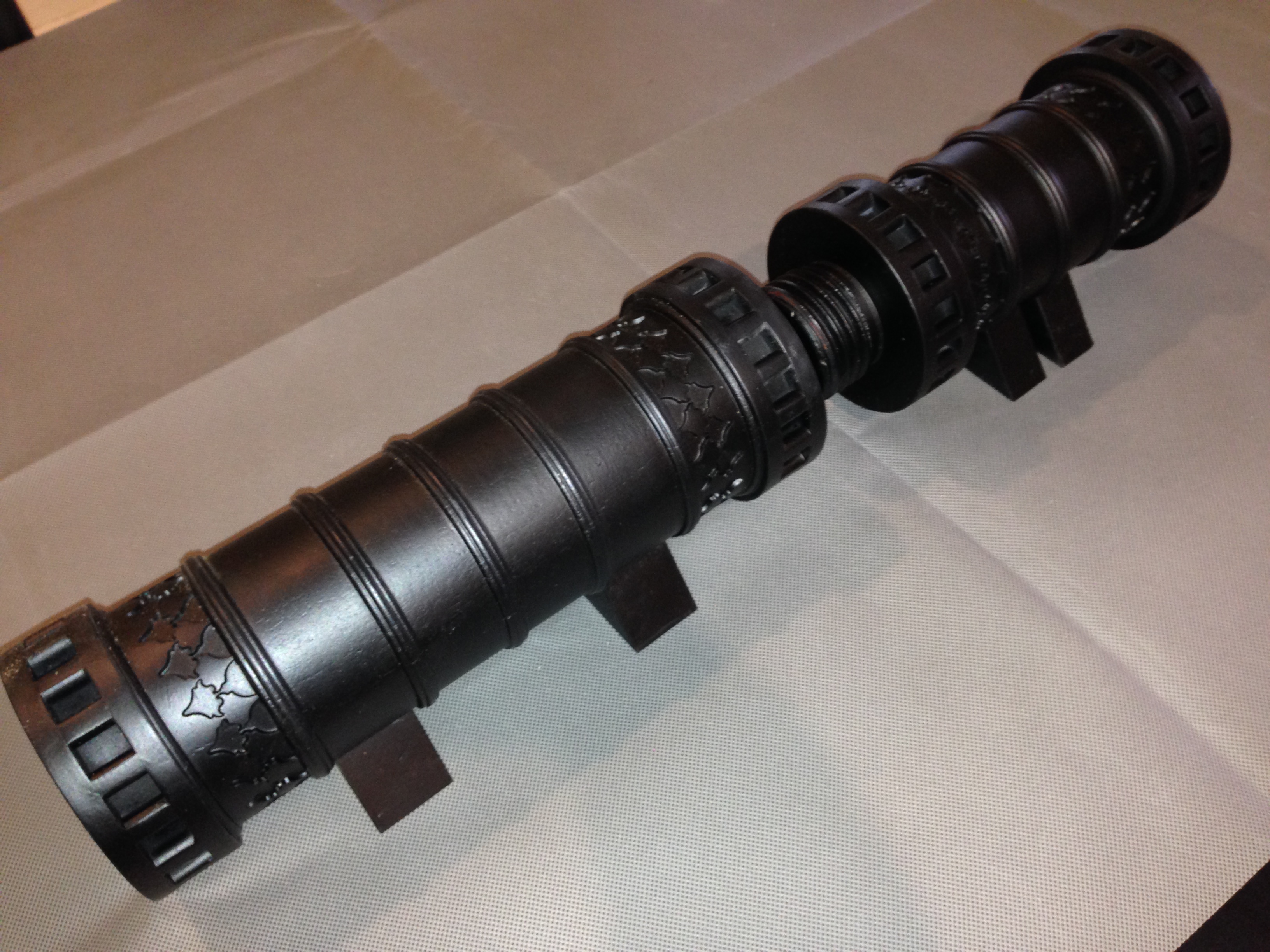
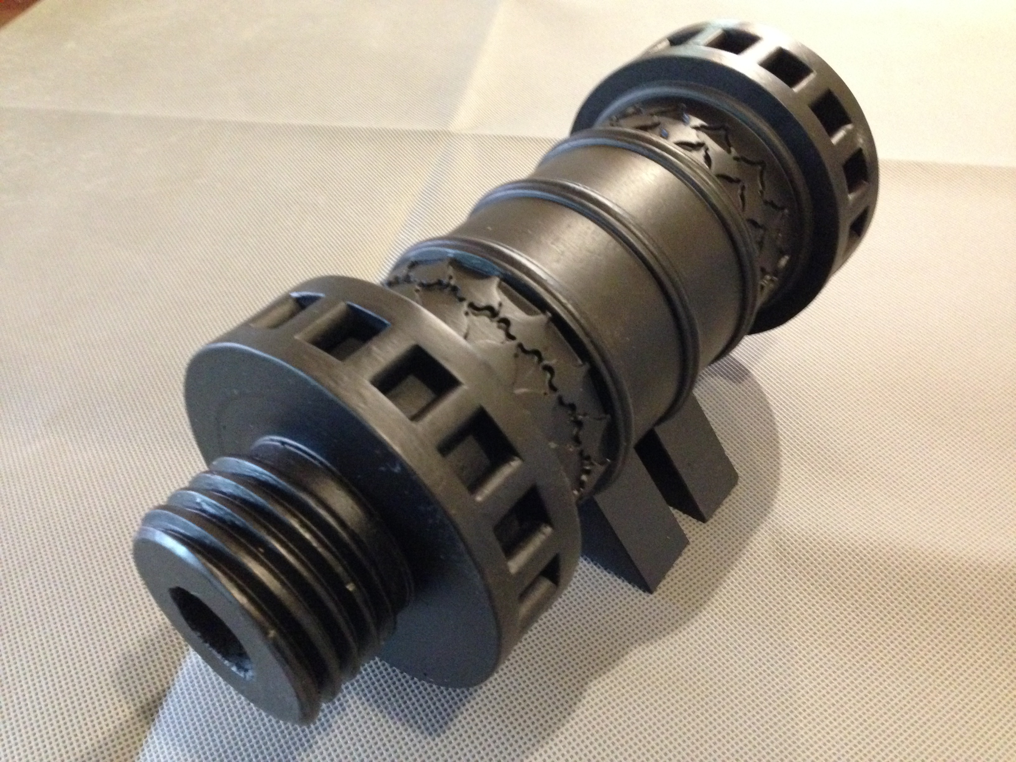
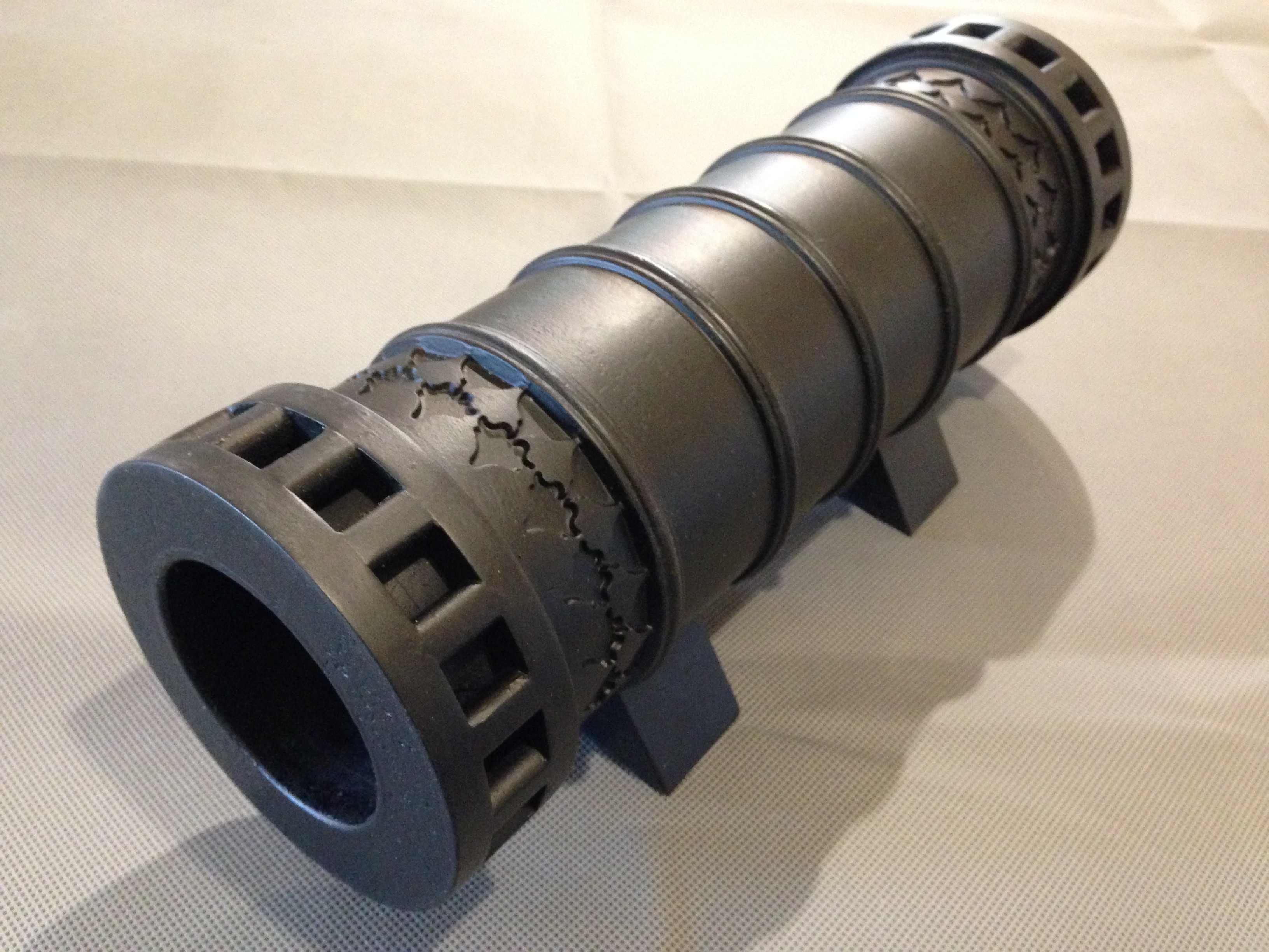
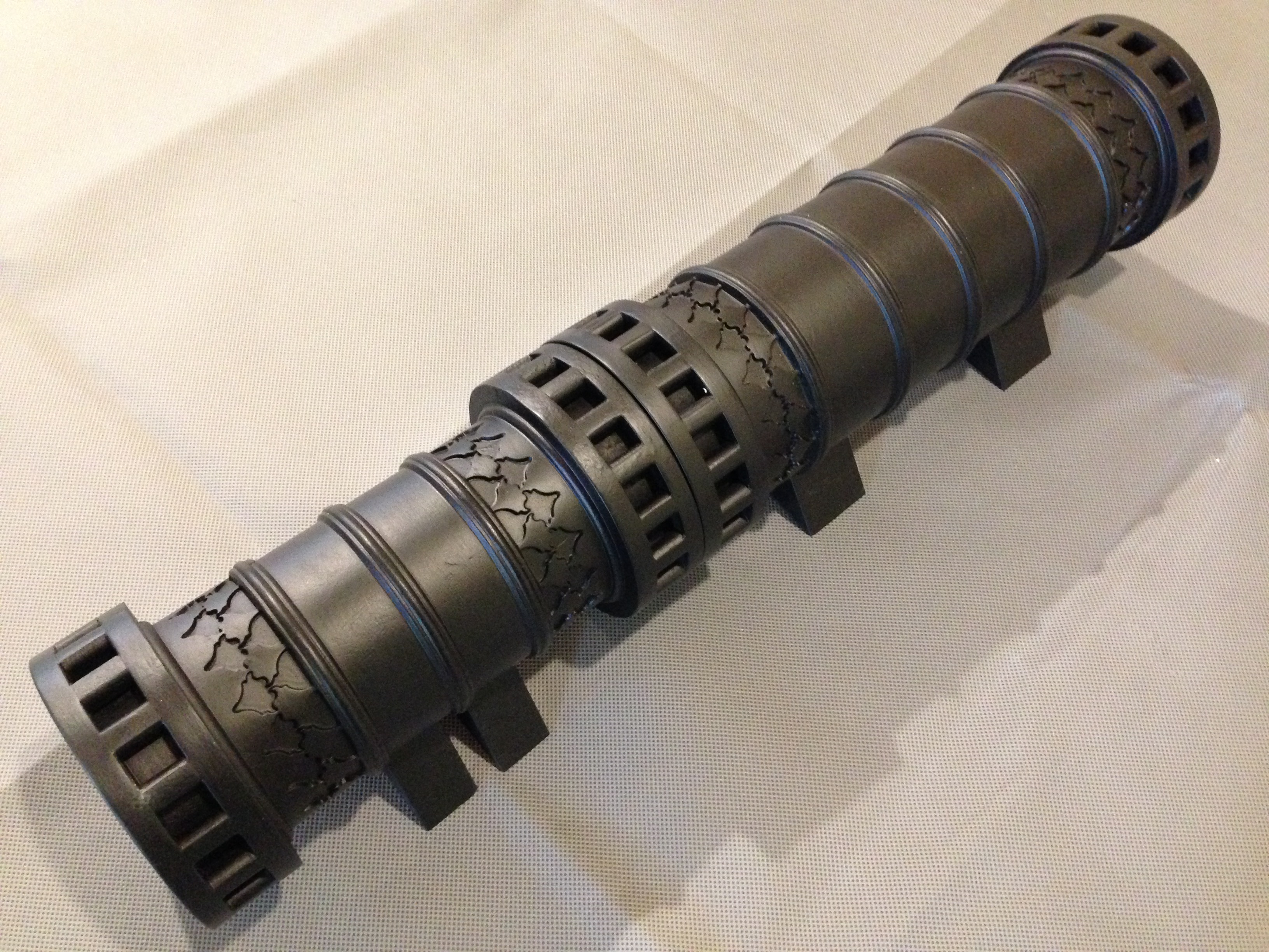
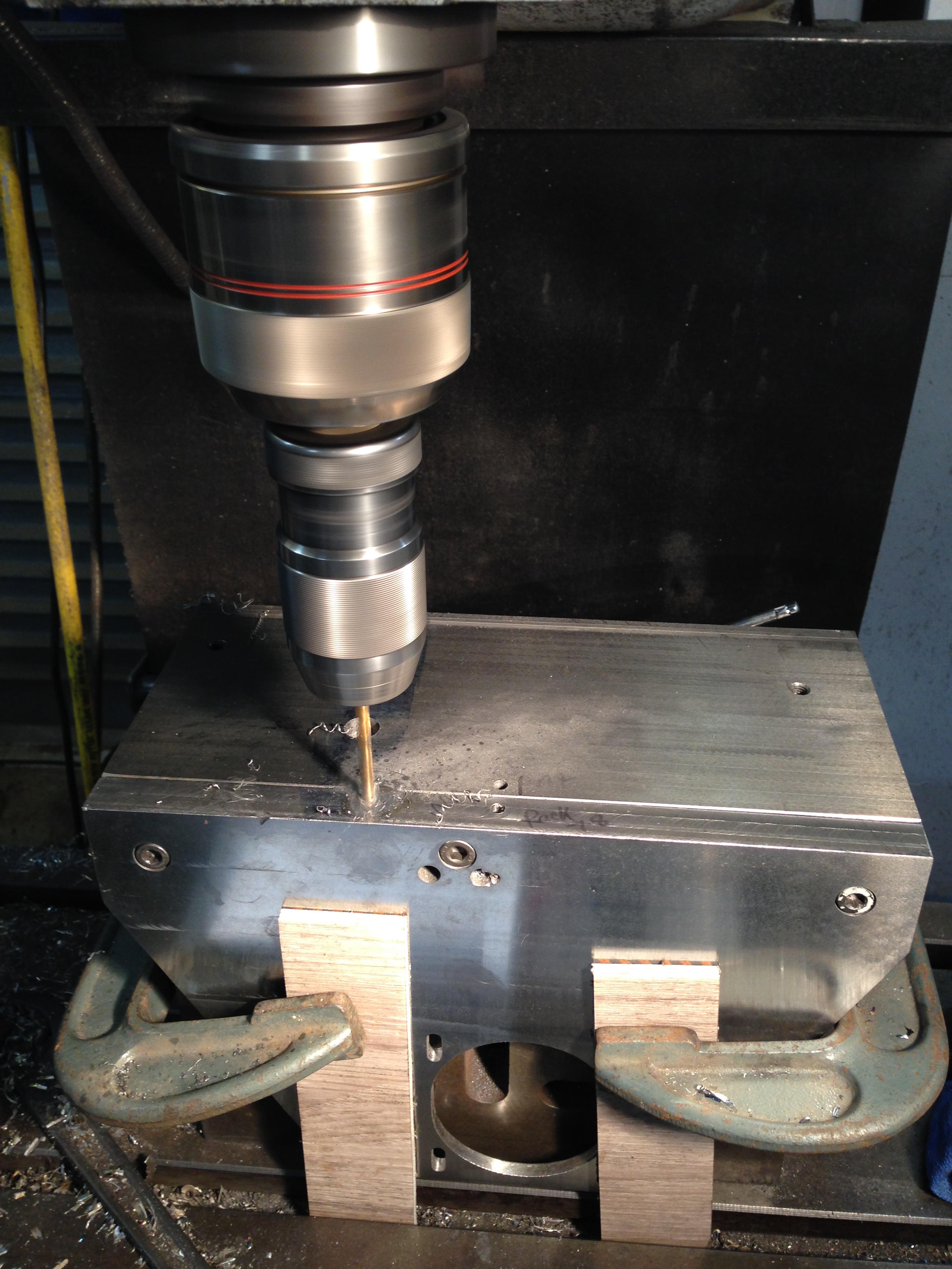
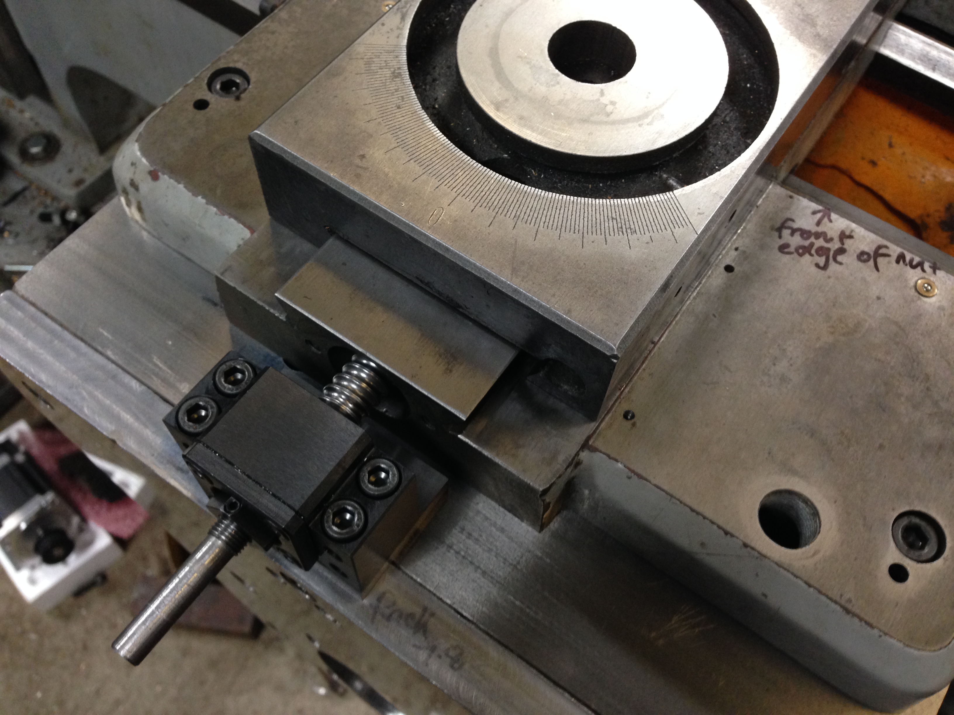
The next print was a tool which I planned for the 3D printer…..

P1053468.JPG

The item is a speed handle for a milling vise.  It is 80mm diameter with some grippy indentations on the circumference.  The tricky feature to make is the hex hole, to fit a 19mm hex shaft.  This is the 3D drawing, imported into the Creality software, so the G code can be generated.

P1053469.JPG

First layers.  Each layer is 0.2mm thick

P1053475.JPG

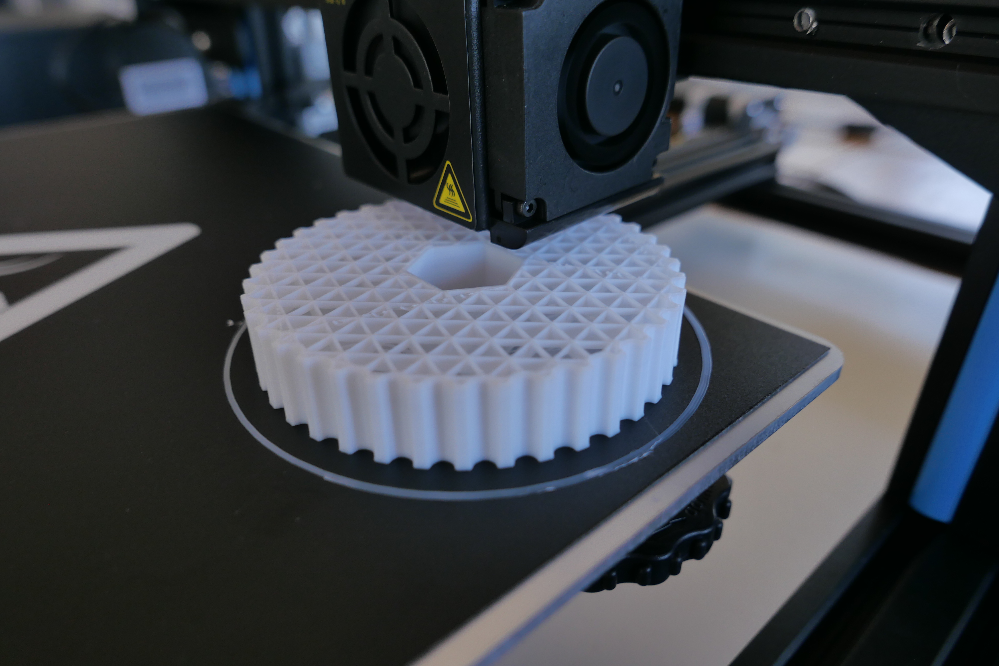
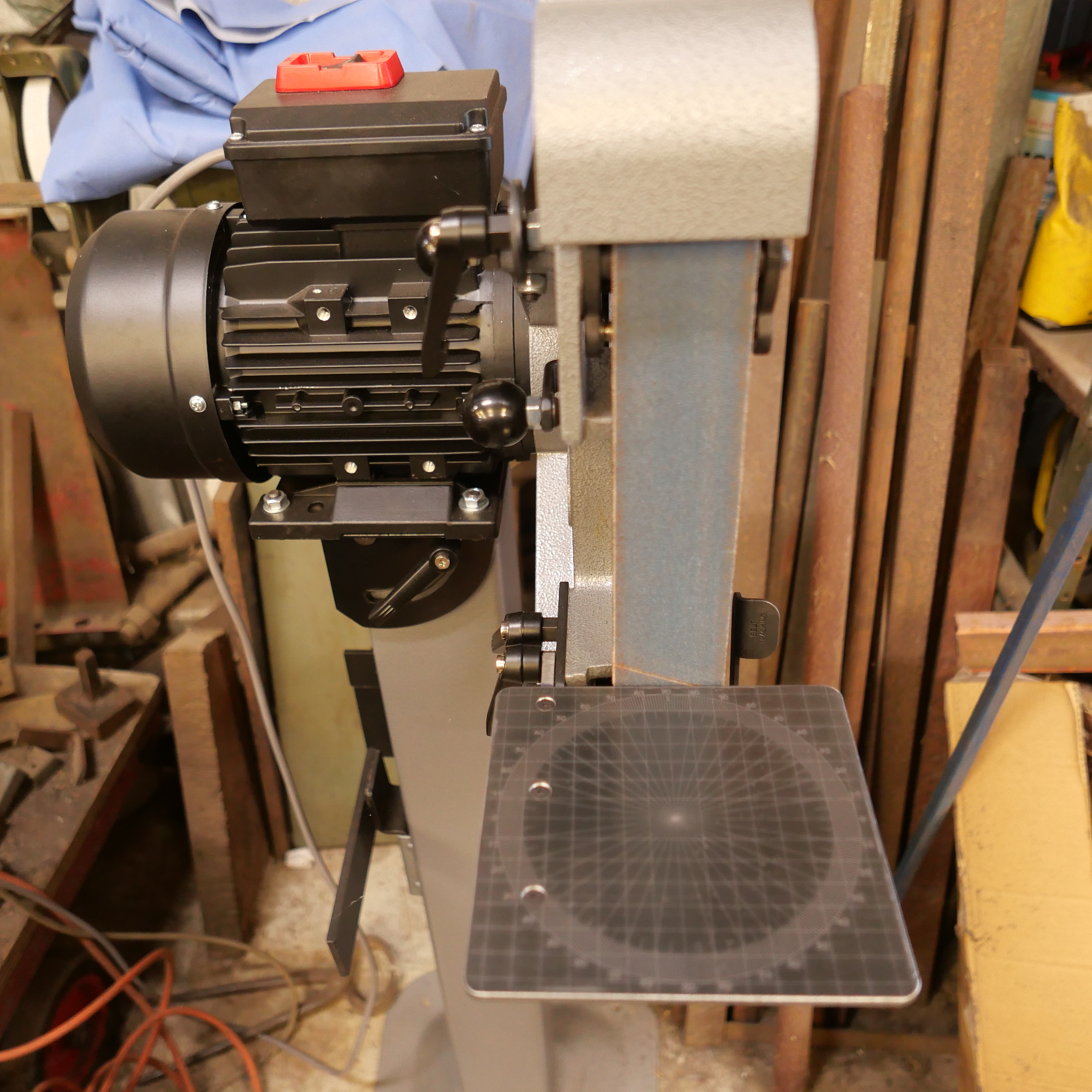
The internal framework is a bit lighter than I wanted.  I thought that I had chosen 90% density.  (ps.  a couple of weeks later.  The speed handle seems to be standing up to the usual rough treatment in my workshop, despite my misgivings about its lightness.)


P1053477.JPG

The speed handle on the vise.  Nice fit.  The print took over 2 hours.

Error
This video doesn’t exist

Not perfect, but too bad at all.


30 watt Laser in action.

Not mine, unfortunately.  This one is Stuart Tankard’s.  It is a Ytterbium generated, 30w, fibre laser, and the wavelength is such that the 0.01mm diameter beam will burn holes in metal.  Ytterbium, for those who can’t be bothered to look it up,  is a rare earth metal, atomic number 70,  Stuart has used the laser to cut parts from a 1.2mm thick hacksaw blade.  And in the following video he is making marks in a work-tool rest which I will use on my Radius Master sander grinder.

P1053243.JPG

P1053242.JPG

It is a 360º protractor, and grid lines at 10mm intervals.   Looks purposeful.  Time will tell if it is useful.

Watch the video.  I am experiencing tool envy.


Listening to my own voice is pretty painful.  I hope that it doesn’t grate too much on you.


Next Tool Project…A CNC Laser Cutter

The Southworth steam powered boiler feed pump has many gaskets.  I have not counted them, but there must be 15-20.  All with many 2mm and 4mm  holes.

And in the process of making the machine, I have broken quite a few of them with the multiple assemblies and tear downs.

But, fortunately, 2 of the members of my model engineering club have laser CNC cutters, so extra sets of gaskets has not been an impossible ask.  (Thank you Brendan and Stuart!)

So, some time ago I asked Stuart, if it would be possible to attach a laser cutter to the CNC mill.  His initial answer was NO.  But recently, he changed his tune.   He attached a laser head to his 3D printed CNC mill and started producing gaskets on request!   So, as is a recent pattern, I am walking in Stuart’s footsteps, and I have purchased a 15 watt laser head on Ebay.   Chinese of course.

Laser kit 15w

This is the kit.   Cost $AuD146.

Laser head

And this is the 15w laser head.  Now I have to work out how to attach it to my mill.  Shouldn’t be too difficult, as long as I don’t turn on the spindle while it is attached.


P1032882

My CNC mill, during the electronics upgrade.  Most recent photo.   Soon to have a laser head.

Stuart assures me that Mach3 can be configured to operate the laser….   turn it on and off, move the axes at an appropriate speed, etc.  I think that some trickery is involved.

And future gaskets will be as simple as ….

So watch this space .

CNC Mill Upgrade -8

Fitted the new VSD Friday.  Ordered Tues pm.  Arrived Thurs am.  Impressive.

$AUD315, inc shipping.   Job cost is mounting.  Still within reasonable limits.

P1032876

The old VSD, top right.  The axis controllers (top left) had not been wired when this photo was taken.

IMG_8151.JPG

The new VSD (variable speed drive) 4kw.  Fitted neatly with some new mounting holes, without any drama.  The rats nest looks less daunting every day.

Now, except for the main spindle motor, there are no more original major electrical components.  All have been updated and replaced, along with the cables.

Yet to be wired are the VSD, coolant pump, oil feed pump, limit switches, homing switches, and the Gecko driver and 48v power supply for the rotary table.   But the mill is useable now.   Video coming up soon.


CNC Mill Upgrade -5

I have been putting quite a few hours into the upgrade, but not much to show photographically.

Finally got the new servo motors installed.  Replaced the X axis belt.  The most difficult servo to access was the Y axis, and of course that was the only one where the alignment of the timing belt was out.   Finally sorted by using a fibre optic camera to see why the belt was climbing onto the flange of the pulley.  The pulley was 1.2mm too far onto its shaft.  I know that, because I solved the problem by inserting washers under the motor mounts.  1mm washers did not work, nor did 1.5mm washers.  But 1.2mm washes did work perfectly.

Today Stuart arrived and removed more of the old wiring.

P1032880.JPG

Stuart, doing another CNC upgrade wiring.

P1032881.JPG

The old 7k computer has been removed, leaving some buttons.  I might be able to use those. The computer enclosure might disappear too.  Not decided yet.

P1032882.JPG

The old CNC mill has lost some weight.  Those cartons are full of old parts.  Note that the floor has been swept.  Stuart was concerned that we might be infested with snakes, but it is winter here, so we should OK until the weather warms up.

P1032883.JPG

The rats nest is disappearing.

CNC Mill Upgrade -2

The major components arrived this week, from China and USA.  Switches, and other components which go “ping” will be bought locally as required.  I am hoping that existing pulleys, belts, brackets will be adaptable.

The motors to drive the X, Y and Z axes are 1.2kW AC servo motors which can be connected to single or 3 phase power.  Each one weighs 6.7kg (14.7lb) .  From China, they are nicely finished.   Substantially shorter than the old servos which they are replacing and slightly larger diameter.  I am hoping that the slightly larger diameter will not cause major problems.

IMG_8088.JPG

AC servo.  There are 3 of these.  Kitchen knife to open the box and for scale.

IMG_8115.JPG

Old Y axis servo on the right, and the new AC servo left.


And each servo motor came with a controller and cables and connectors.

IMG_8093.JPG

And the electronics came from USA.

img_8096.jpg

C11 breakout board.

img_8097.jpg

C10 breakout boards x2

img_8098.jpg

And the Smooth stepper control board.  It is tiny, but the most expensive electronic component.

All up cost so far is ~$AUD2100, of which shipping is about 25%.

Next step is to swap over the servos.  The old shafts are 16mm and the new ones are 19mm.  I intend to machine the bores of the pulleys.  Hope there is enough meat  Tofu to allow that.

Cutting the Gear

Today Swen and I started cutting the gear.  Here is the setup.

IMG_8068.JPG

The gear was centered on the rotary table with an aluminium bush, which fitted the outside of an ER40 collet chuck.  The chuck had an M3 shaft which fitted neatly into the spindle of the rotary table.  3 bolts secured the gear blank to the T slots on the rotary table.

IMG_8085.JPG

This photo was taken after the setup was broken down.  Showing the M3 taper ER 40 collet holder, which I used to centralise the gear blank on the rotary table.

I started the mill conservatively at 200 rpm and a 0.5mm deep cut, but gradually increased the RPM to 450, and the depth of cut to 2mm.   Later adjusted to 300rpm, 1mm cut.

The CNC table performed flawlessly, with rapid advances between the 360/77º degree cuts (about 4.6º each tooth).  The feed rate was controlled by manually winding the X axis feed on the mill.

IMG_8074

We initially used water soluble cutting fluid, but changed later to raw Tap Magic, which seemed to work better.

As you can hear in the following short video, the cutter teeth are slightly off centre, but working well.  Didn’t quite finish the gear teeth in this session.  Some sparks later on, indicated that a cutter sharpening was required before the finishing run.  That will happen tomorrow.

The smoke is evaporation of cutting oil.

The setup will be left undisturbed by removing the gear cutter for sharpening.

I changed my mind about sharpening the cutter in the middle of the job, and continued cutting.

Instead, I lowered the spindle rpm, and the feed-rate.  The sparks stopped.  Maybe I was just pushing too hard, or maybe there was a hard spot in the metal.  Anyway, I finished the cuts.

IMG_8077.JPG

The finished gear cut.  Are those teeth looking a bit skinny at the peaks?

IMG_8078.JPG

Showing the setup from the operator’s view.  The CNC table worked brilliantly.


IMG_8080.JPG

Removing the burrs with wire brush and file.

IMG_8082.JPG

And testing the fit with a trial run in the headstock.  Thanks Swen, for helping (actually directing) the trial run.  The new gear on the left.

I made a video of the gear being rotated through 360mm, perfectly, but for some reason it will not upload.  (did upload eventually.. see below).    It looks perfect, with a tiny amount of backlash.   Full installation in a day or two.  I was quite surprised that making the gear to the specifications worked so well.

IMG_8084.JPG

Me, testing the backlash.

And afterwards, sharpening the cutter on the Quorn T&C cutter grinder which I made a few years ago.  An amazingly versatile tool.

IMG_8086.JPG

IMG_8087.JPG

Just in case I need to make another.

The lathe headstock will be properly reassembled in a couple of days.  But I am finally feeling a bit confident about this job.


New Spindle Motor for the Boxford 125TCL CNC lathe.

Reader Ben asked about the spindle motor replacement on the Boxford.   This is a small CNC lathe, and was often used for teaching in secondary schools in Australia.  Mine was made in 1985, and I replaced the electronics a few years back because they were obsolete and not functioning.  The mechanicals of the lathe were beautifully made and in excellent condition.  I did replace the ball screws, but in retrospect, that was probably unnecessary.   I also installed new and bigger axis stepper motors.

I was still getting some unreliable results, despite the the upgrades, and wondered whether the spindle motor was lacking power.  I was taking lighter cuts to try and cope but clearly a new spindle motor was required.

The space that the motor occupies is fairly tight, and initial searches for a suitable replacement were fruitless.  The new  ClearPath motors looked promising, but enquiries to the manufacturer indicated that the required power and rpm’s were not available.  Then my expert friend (or should that be “friend who is an expert”?), spotted the Ebay ad below, and bought and succesfully installed the servo motor in his 125TCL, so I did likewise.  I am afraid that the electronic aspects remain a mystery to me, so I cannot help with those.  It is a 0.75kW motor, substantially more powerful than the original, but very compact.


Servo Motor.jpeg

Do an Ebay search on the code on the controller.  I paid $AUD339 but it is now plus postage and GST, so close to $AUD400


IMG_6912

The new spindle motor and servo controller


IMG_6910.JPG

A new motor pulley was required.  There is still a high and low belt ratio available, but with the extra power and torque I never use the low ratio.  RPM range is 300-3200.

IMG_6913.JPG

This has been a very successful modification.

Many thanks to Stuart Tankard for his generosity in time, expertise and advice in getting it going.


Project in the Wings.

While finishing the triple expansion steam engine, I have decided on my next project.  Actually, based on my past history of procrastination with the triple, I might even put aside the triple to start on this one.

Reading this article in “Model Engineers’ Workshop” gave me the inspiration to convert a rotary table to electronic control.

IMG_4926.JPG

Dec 2016 MEW article

So I have commenced accumulating the bits and pieces…

IMG_4876.JPG

An 8″ Vertex rotary table.  I have had this for years, but unused since acquiring a universal dividing head.  Should be ideal for this project.

IMG_4908.JPG

A Nema 24 Stepper motor, shafts at each end, so I can use the table manually as well as electronically.  The Microstep driver was supplied packaged with the motor as a kit.  $90AUD inc postage.

indexer pwr.JPG

From the same supplier, a 48volt power supply.  $38AUD

Arduino uno.JPG

The brain of the system.  A programable microcontroller “Arduino Uno”.  I bought 5 of these for $20AUD post included.

arduino display shield.JPG

And an easily attachable display.  To attach the Arduino.  $19AUD

arduino book.JPG

And since I knew nothing about Arduinos, a “Getting Started” book.  Excellent.  On loan from a friend (thanks Stuart)

arduino kit.JPG

And to practice some circuits and get some idea about the Arduino programming, a starter kit of bits and pieces.    $75AUD, but has been very instructive and loads of fun.   The program to run the Arduino is downloadable free from the Internet, so this kit might be a bit superfluous.

And some items of kit.  Each under $20AUD.

magnifiers

A magnifier soldering station, and head light and magnifier

multimeter

A very cheap multimeter.  Previous purchase.  Works fine.  $10AUD

I have disassembled the rotary table, and ordered a 12/8mm coupler.  I am waiting for the coupler before I start designing and cutting the main part to be fabricated which is the piece which joins the stepper and the table.

Also ordered a box to contain the electronics and switches.  Havn’t yet thought about cables,  joiners etc.


Model Ottoman Bombard – Painting

I would have preferred that the title of this blog was “Finishing the Ottoman Bombard”, but I am still waiting for the vectors of the barrel mouth decorations and Arabic (?) writing, and the touch hole.

But I have at least painted the bombard, and the pictures follow.  You will notice that I have not attempted to reproduce the bronze or copper colours of the orginal in Fort Nelson.  Partly because I doubted my ability to make painting such variegated patterns realistic, and partly because the cannon would not have looked like that in its heyday of 1464.  It would probably have been either black, like most SBML cannons (smooth bore muzzle loading), or possibly gaudy golds and reds and blues like other medieval items.  So I painted it black.  I like it.  If I get evidence that it should be more colourful I can change it later.

IMG_4429.JPG

First coat – Primer.  Hmmm… interesting colour.

IMG_4434.JPG

Next coat – matt black brushed on, to fill the hairline wood cracks.  Incidentally, the (dirty) parquetry floor is also made from the red gum house stumps from which the cannon is made.

IMG_4447.JPG

final two coats –  matt black, from a spray can. 

IMG_4458.JPG

So there it is, finished except for the barrel mouth engraving, and the touch hole.  Now what to do with it…   SWMBO says it might be useful as an umbrella stand.

IMG_4460.JPG

The breech.  25mm diameter explosion chamber.  1:10 scale

IMG_4461.JPG

The barrel, 63mm bore.

IMG_4462.JPG

Assembled.  The model is 520mm long.

IMG_4464.JPG

It does need some decoration

turkish-bombard-plan

A Matter of Scale

Before I get onto a brief reflection about scale, the photo below shows 2 cannon barrels.

The big one was what impelled me to converting a manual lathe into a CNC lathe.  That time consuming, costly, and ultimately very satisfying project, started because the CNC lathe which I used to turn the big barrel could only handle the job by doing it in two stages…. doing the breech first then the muzzle.  That was due to the big barrel being too long for the lathe, at 300mm (12″).

The small barrel was a test for the CNC converted lathe just finished, being the first complicated shape which I have made.   To save on material, I made it at exactly half the scale of the big one, ie 150mm long (6″).

IMG_4291.JPG

Comparing the two barrels reminded me, that if an object is twice as big as another, in all 3 dimensions (height, width, depth), it is 8 times as heavy.   And any projectile, and weight of black powder, would also be 8 times the weight.  But the wall thickness of the explosion chamber is only TWICE as thick.

My point is, that if scale is maintained, the smaller the cannon, steam engine, boiler, whatever…..  the less likely it is to explode.

Not that these cannons will ever be fired.  Just hypothetically.

CNC Lathe Conversion – 17

First Test Run

After some test runs without tool or material, I performed some measurements.

500mm movements along the Z axis were reproduced multiple times with a deviation of 0.00mm!  (the Z axis has a ground ball screw)

100mm movements along the X axis deviated 0.02mm.  (the X axis has a rolled ball screw).

I was delighted to note that the lathe is extremely quiet and smooth.  The only noise is some belt slap from the very old belts, and from the stepper motors.

The video below was taken from my iphone, while I was operating the lathe controls, so please excuse the erratic movements.

The steel is 27mm diameter.  750rpm, 50mm/min feeds.

And the guards will be made next step, without fail.

The G code was generated using Mach3 for these very simple shapes.  For more complex items I use Ezilathe.


The lathe is 600mm between centres.  38mm spindle bore.  Swing about 300mm.

CNC lathe conversion -15

Another couple of advances in the conversion.  Today I installed the lead screw cover and the cable protector to the cross slide stepper motor.

The cable protector was easy and straightforward. It flexes in one direction only, and is fixed at the ends after the cable is threaded through it.  The length is adjusted by adding or removing links.  It was placed so that coolant liquid will drain out of it, and to minimise the accumulation of swarf.   The cables themselves have a thick covering and are well protected.  The link protector will not kink, further protecting the cable.

It was cheap.  About $AUD20 for 2 meters, posted from China.  I used about 1.1m.

cnc lathe - 2.jpg

Showing the stepper motor cable protector, and the lead screw protector (one half of it.  The other half is on the other side of the carriage.)

The lead screw protector was another story.  It is a spring steel coil, about 50mm wide, and as it is compressed the coils fit inside each other.  I made a big mistake in allowing it to spring open before I had installed it (there were no instructions).  It immediately opened to a length of over a meter, in coils about 50-60mm diameter.   No big deal, I thought.  I will just compress it back to its original configuration.    Big mistake.

It was what I imagine coiling a live, oily, biting, boa constrictor would be like.  (OK, boas constrict rather than bite.  How about an anaconda, or a big eel.)

I fought it for about an hour.  And eventually succeeded.  Minus a few bits of my skin.

So I did not allow the protectors to expand again until after I had them on the lead screw.

This is what they look like.   Pretty cool IMO.  They just expanded into position when I removed the restraining clips.

cnc lathe - 3.jpg

The lead screw stepper motor and protector.  The Estop box above will get some ends to exclude swarf.

It was not cheap.  The best price that I could find was from South Korea.  $AUD200 inc postage.  But it is excellent Japanese quality.

The wiring is happening, but the variable speed drive seems to be dead.  It has been sitting unused on a shelf for 2 years, so no point asking about warranty.  Took it apart to check for broken wires, fuses, burnt out components etc, but nothing visible.  Will order another one.  About $AUD200.  An unexpected expense.


CNC lathe conversion -14

These lathe CNC conversion posts are probably becoming a bit tiresome, but just in case there is someone out there who is interested, I will continue until the job is finished.

The latest was to make and install a spindle speed (and position – thanks David M) sensor.  It consists of a disk with a slot cut in the periphery, attached to the main spindle.  And an opto-electronic sensor which is connected to its own electronic board, thence to the breakout board and VSD.

cnc lathe - 1.jpg

The disc with the slot at 8:30 and the sensor at 9:00.  I must have chosen the wrong cutter or turning speed for that disc aluminium…  looks a bit rough.  (note added 13/7    Stuart T says that I should have used coolant-lubricant).

cnc lathe - 4.jpg

View from above.  Any clearer?   That gear is now superfluous except as a spacer.

So there is one electronic impulse per spindle revolution.  That is enough to measure the RPM’s.   Essential for cutting threads.

The beauty of this system is that there is no gear selection or changing, and ANY thread pitch can be selected…  metric, imperial, BA  etc…  any odd ball thread that your heart desires.

cnc lathe - 2

cnc lathe - 3

The HTD (high torque drive, I am informed by many readers) pulleys and belts and taper lock fittings.  Unfortunately I could not find a taper lock to fit the small pulleys, so when it is all finally, definitely, absolutely, correctly,  positioned, I will Loctite them in position.  Protective covers yet to be made.  I quite like to see the mechanicals in action, so I am intending to make the covers from clear polycarbonate.(Lexan) .

IMG_4112

The CNC lathe has 3 belts. There is a V belt from the 3 phase motor to the main lathe spindle.  Although I changed the motor and the pulleys, the old belt fitted, which was good.  No hassle. But the stepper motors driving the lead screw and cross slide screw, and their pulleys were all […]

CNC Lathe conversion – 9

The CNC lathe conversion has been happening, despite no posts on the blog.

I have mounted the electronics enclosure, and mounted the various components inside.  No wiring yet.

IMG_4110

This stainless steel tool box is the electronics enclosure.  It fits the space quite nicely, and is adequately big.  The back gear cover to the right will be retained, although the back gears have been discarded.  The main switch and emergency stop will be mounted somewhere on this cover.

IMG_4109

The Variable speed drive (VSD) sits on top.  That will control the spindle speed.  The transformers, stepper motor drives, and Breakout board (the heart of the system) are positioned inside.  Plus cooling fan and filters.  Ready for wiring.

IMG_4107

Drilling the apron to attach the cross slide ball screw bearing.  One chance only at this one, so the setting up took a couple of hours.  The apron is clamped to a large angle bracket on the milling table.   M6 threading followed.

IMG_4108

The end result.  The bearing as attached to the apron and the ball screw is in place.  I machined the end of this ball screw to fit the bearing, cut a thread (M10x1), and machined the end to accept the pulley.  All good.  There is 0.25mm adjustment available if required, but it all seems pretty correct.  The bearing sits on a carefully machined block which is 7.85mm thick.   Still waiting the lead screw machining.(!!)

NOT MUCH GOING ON TODAY

IMG_4092

This is my workbench after I had almost finished tidying it.  Really.  


Then I thought about machining the ends of the cross slide ball screw.

IMG_4095

So I mounted the collet chuck and checked the runout.   0 to o.01mm.  Then I did a test cut in the ball screw.   Hard hard hard.  But it did cut.  Then I chickened out and decided to finish it another day.

So, looking around the workshop for something else to do, I decided to pretty up the new CNC lathe apron.

IMG_4087

Before (milled surface).

IMG_4093

During


And I forgot to take a photo of the after, but it did look nice and smooth and shiny (look at the mirror finish behind the wheel).

Being retired is great!

CNC Lathe conversion-7

I am still waiting for the replacement ball nut for the lathe cross slide to arrive.

Meanwhile, I have been busy machining the supports for the lead screw.

IMG_4054.JPG

Drilling the holes for the support bolts for the lead screw nut

IMG_4055.JPG

And gradually drilling the hole to 49mm!

IMG_4059.JPG

That is a 49mm drill!  First time that I have used it!  Thank goodness for the  FS Wizard app, to give me some idea about feeds and speeds.  Following this I used a boring head to enlarge the hole to 55mm.

IMG_4063.JPG

Gradually enlarged the hole in 20mm steel to 55mm diameter.  and here is the lead ball screw, sitting roughly in its proper position.

IMG_4064.JPG

So this is where I am at.  The lead ball screw is sitting approximately in its correct position.  Considerable adjustment required.  And I am yet to turn the ball screw ends to their correct dimensions.

CNC lathe conversion-6. EBay problem

My first hitch occurred today.

I was very excited to receive the nut for the cross slide ball screw.  If you have been following these posts you might recall that the ground ball screw for the cross slide came from Taiwan, and arrived in 3 days.  But I had to order the nut from a seller in USA.  The nut was advertised as new old stock, but with no packaging.  That was OK, but the postage cost for such a tiny item was ferocious.

It was the last item to arrive from overseas.   However when I looked at it, it was obviously NOT new.

IMG_4043.JPG

The cap screws holding the ball recirculating tube were different from each other, and the washers underneath were too big for the screws.  Obviously not the way that TNK made it.  Somebody has had the nut apart.  And the ball retaining tube was very scratched  and loose.  Again, not TNK standard.

But no biggie.  If it works — fine.

So I turned up a retaining tube to remove the previous nut from the ballscrew, and it came off without any drama.

cnc lathe - 1

But when I tried to fit the “new” nut, it just would not go on.  Tried reversing the direction.  No go.  Bugger bugger.

Somebody has altered or changed the “new” nut.  Maybe installed balls which are too big, or maybe damaged the entry thread.  I do not know.

What to do.  I have been waiting 2 weeks for this to arrive.

First, Ebay email to the seller.  See what the response is.  Ask for a refund.  The postage was almost as expensive as the nut. If unsatisfactory response, they will get the worst Ebay feedback ever.

There is one other seller of these nuts on Ebay, also in USA, and 50% more expensive, and the postage is also 50% more expensive. (how DOES ebay come up with the postage charges.  It seems more related to the cost of the item rather than the weight-size etc.)  But the nuts are in original packaging.  And I want to get going with this, so fuck it.  Pay up and get it.

I will report in a later post.  (if the bad language in this post seems to reflect my state of mind, well, yes it does.)


PS.  Next day.  After sending photos of the issue, the seller accepted responsibility, and I am getting a full refund.  That restores my faith in Ebay/Paypal.   I hope that the next one is in better condition, and comes a bit more quickly.  Sorry for the bad language.

CNC Lathe conversion -5

This is a list of the components which I have accumulated to convert a manual lathe to a CNC lathe.  It is not quite complete, but close.

  1.  Lead ball screw and cross slide ball screw.  Both with nuts and end bearings.  (no pic yet)
  2. The electronic components.

IMG_4021.jpg

The electronic components, not including computer and parallel cable and manual pulse generator.

IMG_4023.JPG

Two stepper motors.  Nema 34, 1200 inch – oz.  With rear covers.

IMG_4024.jpg

A Gecko microstep drive for each stepper motor

IMG_4022.JPG

Cable and connectors for the stepper motors

IMG_4026.JPG

A transformer-power supply (48 volt)

IMG_4025.jpg

Another transformer-power supply (5 volt).

IMG_4034.jpg

3 phase 1.5kw motor (top) to replace the single phase motor (bottom)

IMG_4031.JPG

Timing belt gears 24 and 48 tooth, 5M.  Order belts when size is definitely established.

IMG_4032.JPG

FK20 lead screw bearing and Ball screw covers

IMG_4028

The electronic heart of the system- the breakout board.  A C11R9

IMG_4029.JPG

The index pulse board and sensor.  A C3.

IMG_3342

Manual pulse generator, wireless.

IMG_2718

Variable speed drive, identical to this one on the mill

IMG_4035.JPG

An electrical enclosure, to hold the various components.  This stainless steel box was originally an item of medical kit.  Here I am checking out one possible location.  Not yet definitely decided to use this.

Finally in the electronics section, I will need a computer, loaded with Mach3 and Ezilathe.  Surprisingly, it does not need to be a particularly powerful PC.  And there are advantages in using an older operating system such as  XPpro.  I think there are a couple of those in the attic.  If not, I should be able to pick one up for under $100.

3. Various structural items.  Most of these will be 20mm thick x 200mm wide steel, cut to size and shaped and drilled.  I will take pics of these as I make them.  I was planning to have them water jet cut, but the shapes a fairly simple so I will cut and machine them myself as I go.

So, that is most of the items for the job.  I have spent about $AUD1100 on the ball screws and nuts, about $AUD1500 on the electronics and electrics, and maybe another $AUD500 on pulleys, belts, steel, taper locks, fasteners etc. I will add it all up accurately at the completion.  The lathe was cheap, bought sight unseen a few years ago.   So all up, I should have a CNC lathe for under $AUD4000.  And many pleasant hours of design and machining.  And a great learning exercise.  Stay tuned!

CNC Lathe conversion -4

I am in the process of collecting all of the components for the conversion.  Parcels are arriving from South Korea, Taiwan, China, USA and Australia.  Next post I will take a photo of the bits, before I commence assembly.  I have spent a lot of hours on the computer drawing up the positioning of the new components, deciding which components to get, then communicating with the sellers and making the purchases.  Not to mention hanging around home when parcels are due.  If I duck out for 10 minutes, that’s when the delivery van arrives.  And of course he leaves his little card “sorry we missed you”.

This post I will show you some of the drawings of the proposed conversion.  Of course the first step is to strip the lathe of all of the old manual controls, gears, motor, Digital read out, carriage apron, lead and cross slide screw, electric control box and contents.  (taking photos of every component insitu in case of a change of mind, and restoration required later).

Then measuring the bed and carriage in minute and accurate detail, and drawing it in CAD.

cnc lathe - 1.jpg

This is the lathe side on and end views, showing the new lead ball screw in red and green.  The cross slide ball screw is also there, but not well seen at this scale.  The 4 ball screws at top left are the possible combinations for eventual installation.  The second red one is the position eventually decided.  The green ones are with the nut re-installed in reverse direction.   I really did not want to remove and re-install the nut, because it is pre-loaded, and I do not want to risk disturbing the setup.

Many drawing versions are required, and as the components arrive, I find myself making changes.  This is definitely not the final version.   The two carriages show the carriage in its extreme positions on the lathe bed.

cnc lathe - 1 (2).jpg

This was an early sketch of how I thought I would arrange the cross slide motor and lead screw nut.

cnc lathe - 1 (1).jpg

This is a fairly accurate drawing of a cross section through the cross slide.  Black is existing.  Red is the new nut and ball screw.  You can see that removal of some of the cross slide bed iron will be required.  After looking at this I decided to move the nut and screw up a couple of millimeters.

cnc lathe - 1 (3).jpg

The Internet has been very useful in showing what fittings are available.  These are a few of the catalogues and tables which I have downloaded.  Some sites even provide CAD drawings so their components can be inserted into my CAD drawing to see if they will work together.

Ball Screws -2

This is a brief post to give a 10/10 rating to an Ebay seller with whom I have had dealings recently.

I have bought 2 ball screws and ball screw covers and ball screw bearings in 3 separate transactions from a supplier in South Korea.

Postage was included in the “buy it now” price.  In one case I offered a lower price, which was accepted within minutes.

After paying by Paypal, I received confirmation within an hour in each case, that the item had been shipped (actually air freight by Fed Ex).

In each case the items were delivered to my door in Australia within 3 days!  (it takes 5 days to get a parcel posted from Melbourne to Geelong, a distance of 65km).

And in each parcel there was a very nicely handwritten card thanking me for the purchase, and promising support if there were any issues with the items.

One ball screw was brand new, repackaged as advertised.  The other was used, salvaged from used machinery, but in “as new” condition.   Both were C5 grade, which is normally stratospherically expensive and has to be specially ordered.  They were priced only slightly higher than new rolled (lower grade) ball screws.

They were very carefully packaged in heavy duty cardboard rolls with metal ends, and multiple layers of heavy plastic and foam sheeting.

I made a later purchase which involved the seller removing a part from a machine.  He added it to a parcel which I had also ordered and wrote that I could pay later for the part if I was satisfied with it.  The price for the part (a THK bearing) was $UAUD32.  The same part new here would cost $AUD400.

In every case, communications have been  answered within a few hours, polite, personalised and in excellent English.

My only complaint, and it probably relates to the shipping arrangements, is that there appears to be a size restriction on shipping to Australia, of about 1200mm.  (p.s.  apparently the “do not ship to Australia” are old adverts, and there are no restrictions now.  A message to dy-global is all that is required to get any item shipped).

I hope to deal again with this company.  The name is dy-global.  To find them you need to search Ebay USA, or use the international settings on Ebay Australia.

Lathe conversion to CNC -3 Ball Screws

I have learnt a lot about ball screws in the past few days.  And I have purchased 2 ball screws and nuts on Ebay.  For those relatives and friends who follow this post, who have no idea what I am talking about, the “ballscrews” are what determines where the cutting tool on the lathe is positioned.  Very crucial.  (can something be “very” crucial?  It looks a bit like “very unique”. )

1

Ball screws are the usual positioning screws  for CNC machines these days.  The alternative is Acme or square thread screws, but the few manufacturers who used to use these have all switched to ball screws (as far as I know).  Even Wabeco, the respected German lathe manufacturer no longer specifies any threads except ball screws.

Ball screws require less power to turn due to friction being a fraction of the alternatives.  Ball screws are silent.  If they are noisy there is something wrong.  They are generally more accurate than square or Acme threads.  They used to be many times more expensive than the older types, but since China/Taiwan has taken over most of the manufacturing, often using equipment sourced from US/Europe/Japan, the costs have plummeted.

And the backlash is minimal or zero.   Another name for ballscrews is “antibacklash screws”.

Backlash is annoying on a manual lathe, but it is very important on the cross slide of a CNC lathe.  Interestingly, it is less important on the CNC lathe lead screw, because most CNC lathe machining  on the leadscrew occurs in one direction only, towards the headstock.  However,  the cross slide is machining in both directions, in and out,  so the absence of backlash is necessary to maintain workpiece accuracy.

Ballscrews have grades of accuracy varying from C0 -C20.  The bigger the number, the less accurate the screw.   In general, it is recommended that industrial lathes should be C3-C5,  which means zero backlash, and accuracy of about 0.001mm.  That degree of accuracy is quite expensive, costing thousands of dollars per screw, and only attainable in ball screws which have been finished with precision grinding.  The alternative is ball screws which have been “rolled”.  These are much less expensive, costing hundreds of dollars per screw, depending on the degree of accuracy.  The best rolled screws can attain an accuracy of 0.01-0.02mm (C7), down to 0.1mm (C20).  These are approximate figures which I have gleaned from several manufacturers’ specifications.

So from scale drawings of the lathe bed and carriage and cross slide, I worked out that I needed the following…


IMG_3978.JPG

This is a photo of a ball nut and screw very similar to what I have bought for the cross slide.  THK brand, 14mm diameter screw, 4mm pitch, and BNT nut style.  Note the rounded channels that the balls occupy.


  1. Cross slide screw 14mm diameter, 400mm long with at least 200mm of thread, and a thread pitch of no more than 5mm.  The cross slide nut needed to be a THK BNT pattern in order to fit into the cross slide with a minimum of space making machining.  THK is a large manufacturer, with intermediate prices, and a very good reputation.  The screw needs to be a specific length, and one end needs to be machined to go through a bearing/ bearing housing and have a tooth belt pulley attached.  I contacted a ball screw supplier, to enquire about ground ball screws, but discovered that these were rarely specified due to their cost, and delay of 3-6 months.  A C7 rolled screw with the BNT nut was going to cost about $AUD400-450.  So I searched Ebay Australia, Ebay USA, and Ebay UK.  Eventually, I found and bought a used ground screw with end bearings and housings from Taiwan for $AUD250.  The nut was the wrong type, but I found a new correct style nut on Ebay USA for $AUD100.  I know that sounds like I have not saved much money, but that gives me a super-accurate ground ball screw!  Of the correct size and type.  I am keeping my fingers crossed that the pieces sourced from different countries will go together.  Theoretically, they should.  (same manufacturer, same size, “ground” specification, etc etc.  but finger tightly crossed).
  2. The lead screw approximately 1000-1100mm long, 25-32mm diameter, and 5-6mm lead.  Super accuracy not required in the lead screw, and I could have bought a new rolled one from China for about $AUD300-400.  But then I spotted one in South Korea, new old stock, 28mm diameter, 6mm lead, with unmachined ends.  THK brand.   Asking price just within budget.    And this was a C5, ground screw, possibly more accurate than I expected for the price, and unused, but hey, it sounded like a bargain.   So I offered about 15% less and was somewhat surprised to have the offer accepted.   So that one is arriving in a week or two.  Then to buy mounts and arrange end machining of the screw.  Although not crucial it will have zero backlash, due to the C5 designation, and the fact that it has two ballnuts bolted together in a “pre-loaded” fashion.  I expect that it will be the most accurate component on the lathe!  No decent photo to post.

(ps.  see the comments section for discussion about axial accuracy and backlash.  A super accurate C5 ballscrew has axial play (backlash) specification of 0.020mm, but the double ballnut configuration will reduce that number substantially.  “zero backlash” apparently does not really mean zero.)


Lathe Conversion to CNC -2 and Wall Smashers

After removing most of the lathe gear which will not be required after the CNC conversion, the lathe is looking a bit naked.

The carriage apron, the lead screw, the back gears, the drive rod and control rods have all been removed.  Also the cross slide screw and handle.  The cross slide itself is temporarily removed, but available for measuring for fitting a ball screw.

I have now made accurate measurements and drawings of the lathe bed and carriage, in order to choose ball screws and nuts for the lead screw and cross slide.

The lead ball screw is easy.  There is plenty of room and machined surfaces for attachment.  I see no particular problems there.  Just time, careful machining and expense.  Chinese or Euro-American?  As usual, there is a big price difference and maybe not such a big quality difference as previously.   Looking at 25 or 32mm diameter, with 550-600mm of thread.

The cross slide ball screw is another matter.  The current cross slide square thread screw is 14mm diameter, and I would like to use a ball screw about the same size.  The problem is that a ball screw nut is considerably bulkier than the existing square thread nut, so some machining of the cross slide will be required to make space.  The cross slide dimensions are already fairly tight, to maximise the swing over the carriage.  I do not want to weaken the cross slide too much.  So it is all a bit tricky.  Time to consider options. And to get another opinion.

No lathe pics, so here are some of Turkish wall smashers.


Turkish cannon

This one was given to Queen Victoria by the Turkish sultan.  It was made about a decade after the fall of Constantinople.  It was cast in 2 halves.  There is a giant thread connecting the halves.  I imagine that the strange square holes are to allow levers to be inserted for the screwing by many strong men.  No double entendre  intended.


Turkish wall smasher


Turkish cannon and ball

This one could have been used to make the breach in the wall at the fall of Constantinople 1453.  That stone ball is 600mm diameter.  With no trunnions or other supporting mechanism the barrel was probably dug into the ground for support.  That would allow repeated shots at exactly the same point in the walls.  8-11 shots per day.  It was made for the invading Turks by Orban, a christian who had previously offered his services to the defending Byzantines.  The Byzantines whose empire by this time had been reduced to a tiny fraction plus the city itself, could not afford his services.  The rest is history.


Lathe conversion to CNC

The carronade is finished, as far as I intend to take it.  At some future date I might make pulleys and ropes etc, but at this stage I am putting it on the mantlepiece.  (mantelpiece groans).   Some detailed pics in a future post.

I have commenced my next project.

I have a CNC lathe but it will accept work up to only 125mm diameter and 125mm long.  It was not big enough for the long gun, and barely fitted the carronade.   And I have some ideas of further larger projects (field artillery pieces, and possibly a model of a Turkish wall smasher like the ones which allow the Turks to conquer Constantinople.  That one was almost 6 meters long, and fired stone balls of 600mm diameter!!!   So even at 1:10 I need a bigger lathe.

OK, so I could use a manual lathe, but that is not the point.  A bigger CNC lathe would be fun.  And I have a Taiwanese one which I think would be suitable for conversion.  It is 600mm between centres, (just big enough for my Turkish smasher), and about 300mm swing.  It is not pleasant to use as a manual lathe due to very noisy spur gears.  So I have decided to convert it to CNC.

The steps are:

  1.  Remove the existing lead screw, cross slide screw, apron, back gears, gear box and more.
  2. Measure for ball screws and buy them.
  3. Buy the electronics.   Stepper motors (7amp NEMA34), break out board, Gecko stepper drivers, limit switches, power supply, 3 phase 2hp spindle motor, etc etc
  4. Fit the ball screws and motors.
  5. Fit the electronic components and hook them up (Stuart, I hope that you are reading this)
  6. Configure Mach3 and Ezylathe on an old computer
  7. Make a Turkish smasher

I have made a start.  Removed most of the unwanted manual components from the lathe today.  It felt very threatening and unnatural to be wrecking a perfectly good lathe.  See the photos.  At this stage I am taking lots of photos in case I have a change of heart and restore it to its original state.  But I will press on.  Watch this blog.  I expect that the conversion will take a couple of months, by the time components arrive from overseas.


IMG_2362.jpg

The lathe prior to CNC conversion


CNC conversion - 1

After removing the lead screw, apron, gear box, cross slide back gears etc etc.  Looks a bit naked.  Not much remaining.


Boxford CNC lathe (5)

The following pictures and video were supplied to me by Stuart Tankard.

They show the rarely used tailstock in use, supporting a relatively long thin workpiece.

The lathe is Stuart’s, and his control panel is fixed to the lathe cabinet.  (Mine is an identical machine except that I use a  wireless MPG).

The tailstock is the part coloured bright yellow, and it normally sits unused in a drawer, or hinged down and out of the way.  As you can see however, it occasionally is useful.

20160102_160913.jpg

Stuart’s lathe.  Note that the G code for the part was generated by a program called EZILATHE.   I also use this very handy program.  Ezilathe is a free download.


20160102_155138

The part is the first step in making a link for the beam engine which Stuart is completing.  The headstock end is held in an ER collet.  The tailstock contains a small roller bearing held in a shop made fitting.  After turning, the tear drop ends will have flats milled onto the sides, then holes drilled and reamed for shafts.

Check out the following Youtube video to see Stuarts lathe in action.