johnsmachines

machines which I have made, am making, or intend to make, and some other stuff. If you find this site interesting, please leave a comment. I read every comment and respond to most. n.b. There is a list of my first 800 posts in my post of 17 June 2021, titled "800 Posts"

Tag: Ezilathe

G Codes for CNC Lathe. Ezilathe.

Most hobby modellers who use a CNC lathe, run the lathe with Mach3 software. Some have progressed to Mach4, but apparently 4 is not straight forward, and my expert advisor says that it is best to stick with Mach3 for the time being.

Mach3/4 requires instructions to control movements of the lathe carriage (X and Z movements), spindle on and off, spindle speed, coolant on and off etc, and those instructions are in the form of G codes.

G coding is not difficult to learn. There are excellent YouTube tutorial videos on the subject, Udemy courses, books, and so on.

The problem is that mistakes in G coding can be easily made, costly, and sometimes scary. The biggest problem is that G coding is time consuming.

Fortunately, software is available to make G coding automatic, fast, and reliable. This post is about the program which I use for G coding. It is called Ezilathe. It is available at no cost as a download from CNCZone. (see details of downloading later in this post).

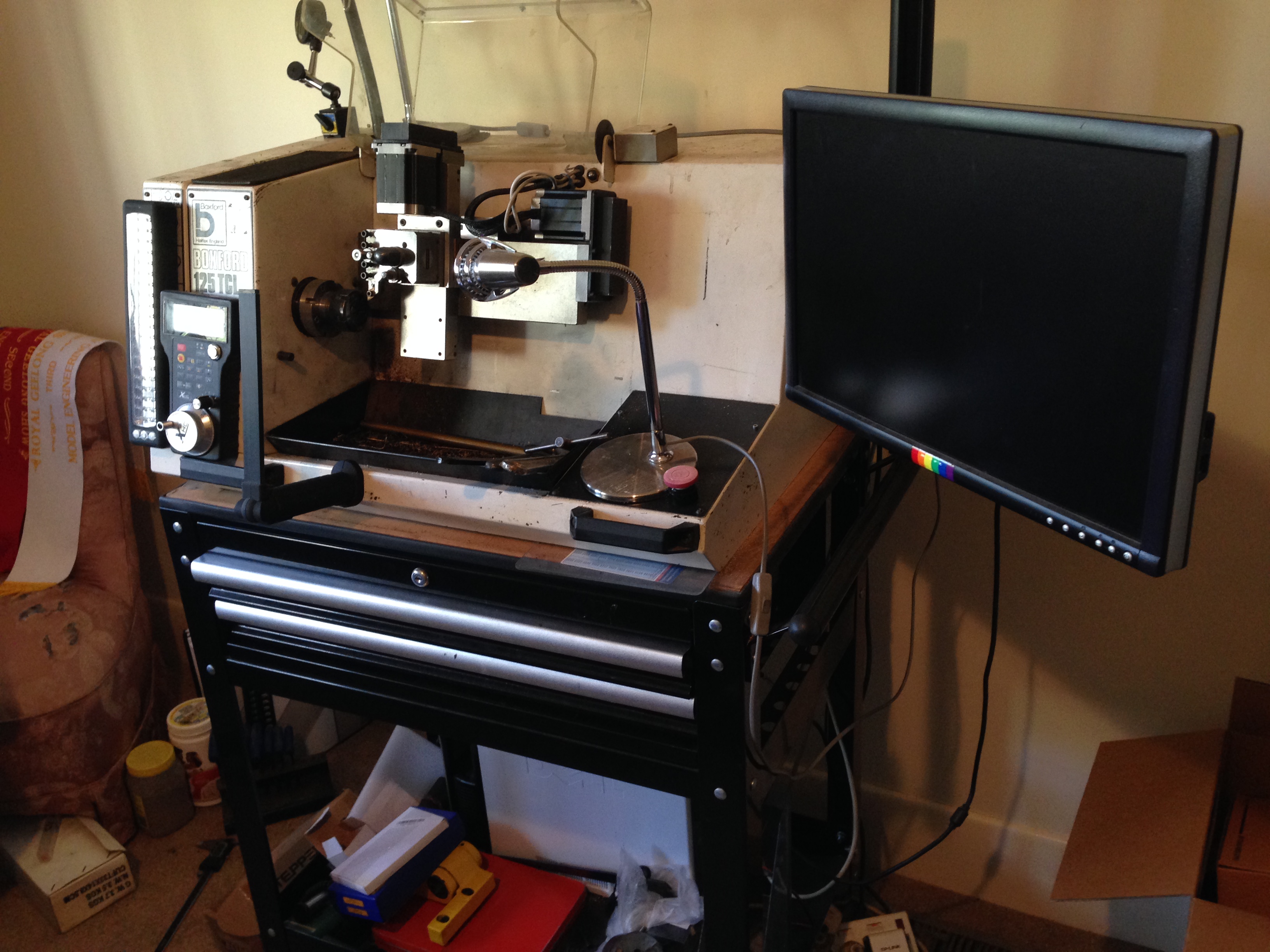
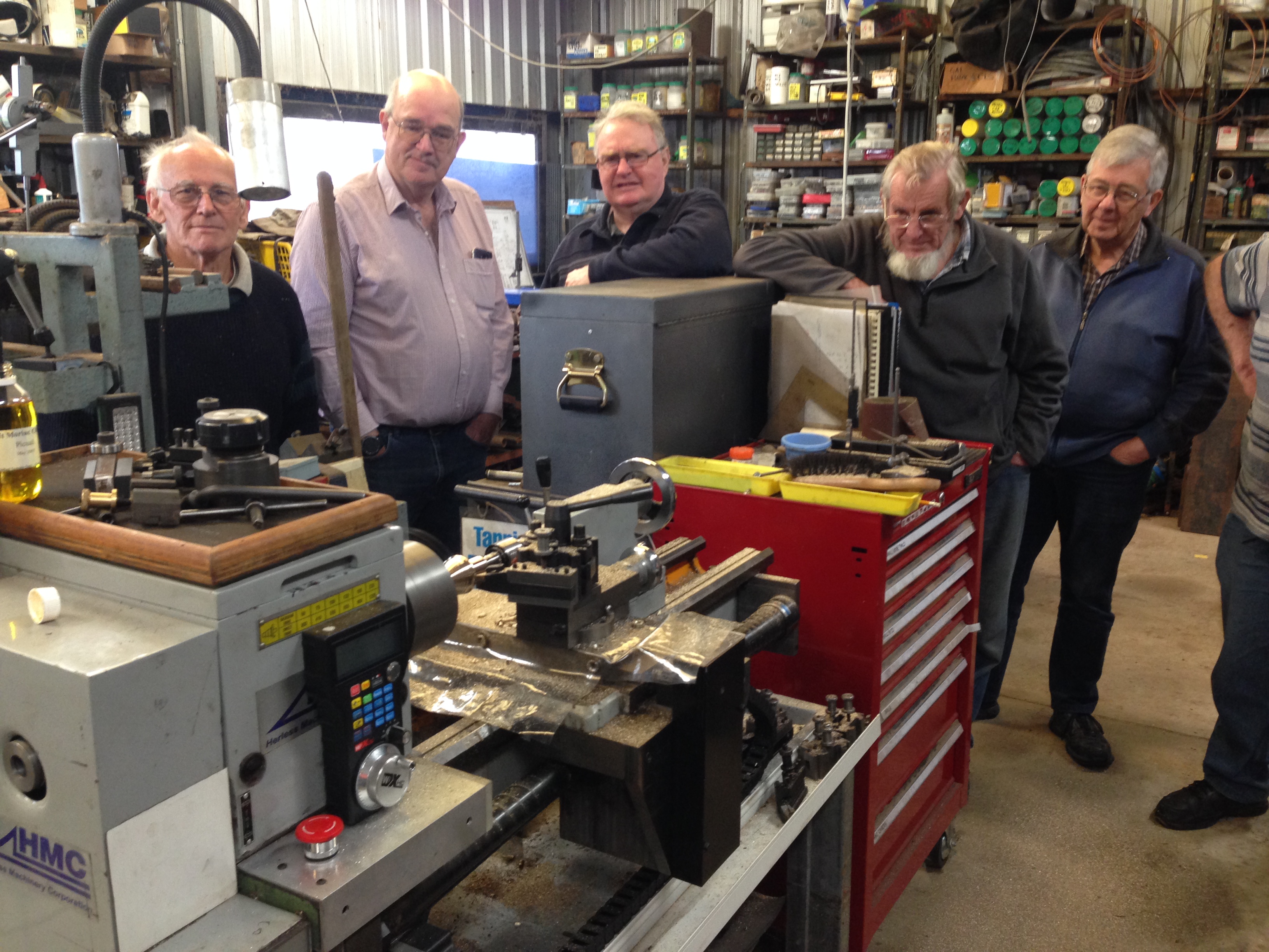
Ezilathe was written by Stuart Tankard, who I met a decade or so ago at a meeting of GSMEE. Stuart gradually persuaded me to get into CNC, and frankly, the decision to do so has resulted in a quantum leap in the scope and standards of my model engineering efforts. Now I use a CNC lathe, CNC mill, CNC rotary table, CNC 3D printing.

But I digress. This post is about G coding for CNC lathe. Until Ezilathe came along, I was programming G codes manually, making mistakes, and consuming lots of time. And experiencing crashes. Exciting, damaging, and sometimes dangerous.

To CNC turn an object, the profile must first be drawn with a CAD program such as AutoCAD. There is a very basic CAD drawing facility in Ezilathe, but it is so basic that I prefer AutoCAD. In AutoCAD I then rotate and move the object as it would be held in the lathe chuck, and move the tailstock end of the profile to the X=0, Y=0 position. Only half of the original drawing is required, so I delete everything below the X 0 line. I delete or hide all lines which are not part of the profile. The profile can be saved as a polyline, or as separate lines, arcs, splines etc. It is named and saved as a dxf file.

Then Ezilathe is opened, and the dxf file is imported.

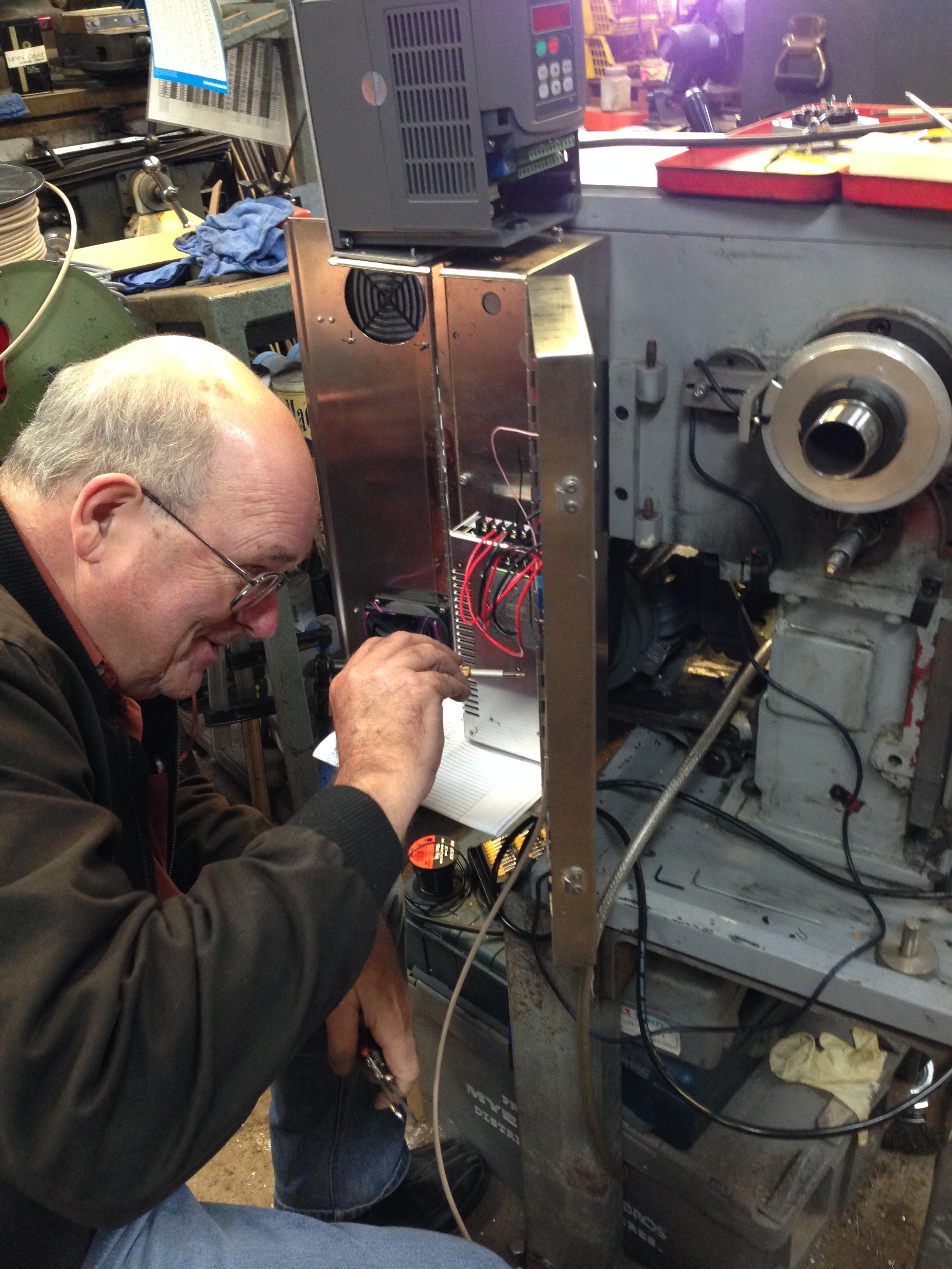
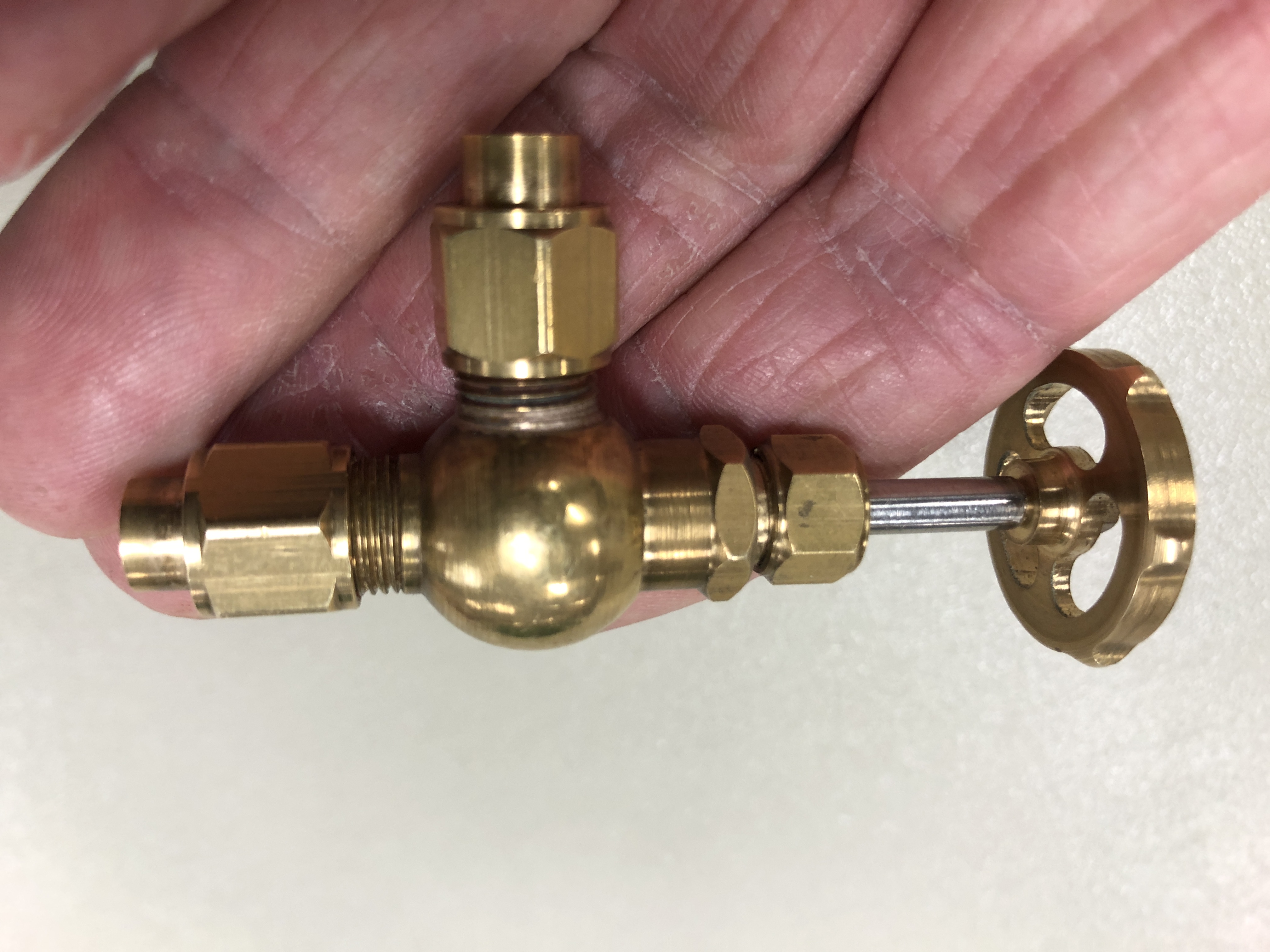
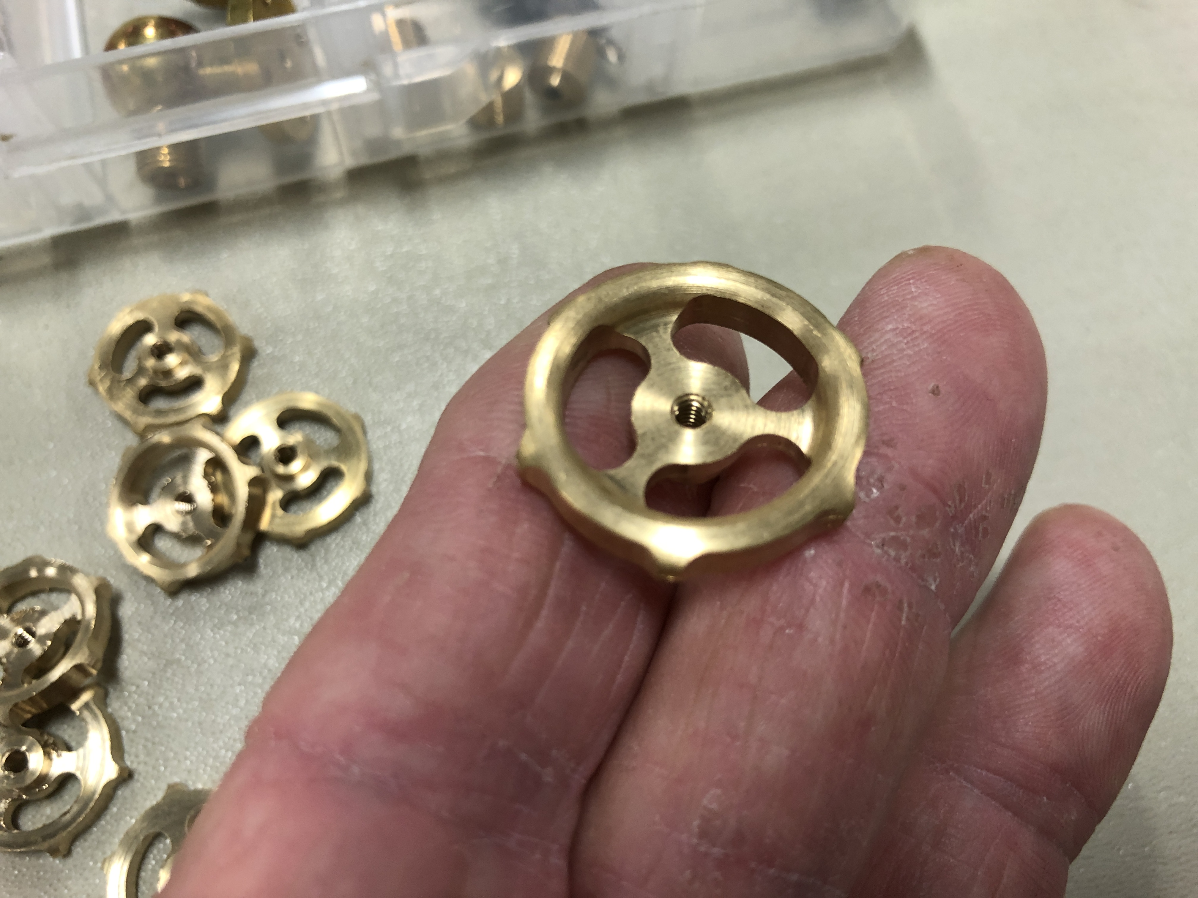
The stock diameter is entered. The z position of the tailstock end of the profile is entered (usually Z=0). Feeds and speeds are entered using the tables in Ezilathe or another source. I use an app named “FS Pro”. Also select which lathe tool is to be used (the lathe tools are all entered in advance) or select a “point tool” which has an infinitely sharp point, and no width. In the example shown in the pictures below the turning was achieved with one tool. If multiple tools are required on one job, each tool will have to been set in the tool editor. So far I have not used the tool editor, but I can vouch that it works well, having seen the superb results which have been achieved by Stuart.(see the photos below)

Then the polyline of the profile, OR, each line and arc etc is selected in the machining sequence. Important not to miss any small lines or arcs as unintended results can occur. That is why it is sensible to save the original drawing as a single polyline. (Stuart tells me that any gaps will be automatically filled by Ezilathe as straight lines.)

Then go to the simulator, and see how Ezilathe will manage the sequence of cuts. In the picture below, the cuts are the straight lines, and there are 2 finishing cuts along the profile.

If all looks well, generate the G code. I usually visually scan the G code, looking for obvious errors. Usually there are no errors. Save the G code. Then ready to use the G code to make the part.

AN air cut with no work stock or cutting tool is sensible for beginners.

This was a demonstration of Ezilathe to GSMEE members. Stuart Tankard watching carefully to correct any of my errors. The G code is on the right side of the drawing.
This is the CNC turned finial, which was demonstrated to GSMEE members. Fortunately the turning all worked out well.
I made this bookcase about 30 years ago. Can you see the finial? It was a very delayed addition.
Now some examples of items made by Stuart using Mach3 and Ezilathe. All of the components in this valve were made by Stuart.
And when he makes an item he finds it difficult to stop churning them out!
pretty rough hey!
Stuart made this cutter to make the seats on the valves. Some turning on the lathe using Ezilathe, and some mill work. And heat treatment. Not bad hey!

There is a lot more to Ezilathe. This has been a very brief introductory summary. Creating a lathe tool library, and entering startup strings for different lathe setups for example.

To download Ezilathe, you need to register at CNCZone. It is quite a good, useful site. In CNCZone go to downloads, Postfiles, Page 2. Select Ezilathe, and Ezilathe.pdf. The pdf is a comprehensive manual. Save them to a directory named C:\Ezilathe and unzip them. The program has been fine tuned, and updated. The latest version is 1.7.3. Then, on page 1 of Postfiles there is a small bug fix, Version 1.7.3.3. 1.7.3.3 is an executable which should be run after 1.7.3 is installed. If there are problems or questions Stuart can be contacted via CNCZone.

I have no hesitation in recommending this excellent program. It is just amazing that it is free.

Boxford 125TCL CNC Upgrade

This small CNC lathe was converted from the original c1985 electronics, to components which are compatible with a PC running Windows XP and Mach3.

Reader Paul M asked about circuit diagrams.  I must confess that I do not have such.  Indeed, I would not understand them.  The electronic connections were made by my expert friend Stuart T.   I believe that Stuart intends to write up the conversion for one of the Australian magazines, and possibly this post might give him a gentle shove~.

In passing, I should give Stuart a thumbs up for his excellent CNC lathe program, which is far superior, in my opinion, than Mach3 for running the CNC lathe.  It is called Ezilathe and is available as a free download.

Anyway Paul, here are the promised photographs of the electronic components of the Boxford, after the conversion.  You should be able to work out many of the connections by zooming in.


IMG_5380.JPG

The Boxford 125TCL sitting on a bought trolley which could have been made to measure.  The PC is on the bottom shelf, the extra toolholders and tools in the drawers, the wireless MPG on the front, and upgraded stepper motors in black.

IMG_5394.JPG

The rear view to show the extra power outlets to supply the screen and PC.  I still operate this lathe in a spare bedroom of my house.  Very handy if I have a sleepless night.  It is so quiet that it does not disturb SWMBO.

IMG_5382.JPG

The view with the back open.  The only components from the original setup are the spindle motor, the main switch, and the Gemini controller (RHS with orange cover).

IMG_5384

Power outlets, main switch and power supply.

IMG_5385.JPG

Transformer.  Can’t remember what the Fotek is for.

IMG_5386.JPG

IMG_5387.JPG

IMG_5388.JPG

Gemini with cover removed.

IMG_5389.JPG

C11 R9 Breakout board, the optical indexer (top), and Gecko stepper drivers (LHS), parallel cable from the PC,  all mounted on an aluminium plate.

IMG_5390.JPG

Spindle motor, original.  But now considering upgrading to a more powerful motor.

IMG_5391.JPG

new cable junction box for the stepper cables.

IMG_5392.JPG

New cooling fan, top LHS

So, I hope that these shots are some use.  If you do not recognise the components, I suggest that you follow my example and bribe an expert friend to do the connections.

Metalworking for a cabinet maker

Our model engineering club has been locked out of our club rooms because MOULD has been detected in the building.   Apparently a lengthy process to reduce the mould to acceptable levels.  (note to self…. make sure that the inspectors never set foot in our house).

So our meetings have been held in various locations, including a sports centre and a basketball building.   I feel quite virtuous when I enter these buildings, but for some reason I do not feel any fitter when I exit.

A recent day meeting was held at my farm workshop.  Not my farm anymore, just the buildings.

walls-of-constantinople

Not that one….   the other one.

And one of our more senior members requested a display of CNC machining, from design to product.

So, I drew up a finial which was required to complete a bookcase which I had built 30 years ago.  Then imported the DXF drawing file into “Ezilathe”.

Ezilathe on screen.JPG

Showing Stuart Tankard, the author of Ezilathe, scrutinizing my drawing ….  and offering excellent suggestions for improvement using Ezilathe.

Then used Ezilathe to generate the G codes…..

Then to the CNC lathe…..

turning the finial.JPG

CNC turning the finial in 51mm brass rod.  1600rpm, 100mm/min.  Controlled by Mach 3 Turn.  I removed the tailstock shortly after this photo was taken, to permit completion of the ball.

GSMEE CNC close.JPG

Some GSMEE members watching the CNC turning.  I spent 3 days clearing up the workshop so the 16 members could fit in.   Amazing how much space was revealed in the workshop.   This is the Taiwanese lathe which I converted to CNC.  See old posts for details of the conversion.

I watched anxiously as the part was gradually revealed.  Admittedly, I had had a test run in wood to check the parameters, but this was the first run in metal.

finial in hand.JPG

The finial.  The bar stock was parted later.

finial on bookcase

Bookcase finally finished, after 30 years.

If you are interested in CNC lathe work, you should take a look at “Ezilathe”.  It is superb.

If you are on Facebook, (of course you are if you are reading this), you might like to take a look at the GSMEE Facebook site.


Bombard Model-3 turning the barrel

Another session or two, and this project is complete.

Now how do I make a cannon ball 62-63 mm diameter?  In wood will be ok?  Does not have to be granite.  I could make a mould and cast it in aluminium or lead, but stone would be authentic…..   thinking.

ps.  Re cannon balls.  I will cast them, in cement!   Now, how to make a mould.

Bombard Model. Turning the Breech


So if you watched the video, you can see that I have a problem with the big thread between the breech and the barrel, at least in the wooden prototype.  It might work better in brass or gunmetal.

The thread has a pitch of 6mm and a diameter of 60mm.   It is big.

My plan at this time, is to make a brass male threaded section, and glue or screw it into the breech.  Then to make a steel tap using the same G code, and cut a thread into the wood of the barrel.  (p.s.  note 30 Sep…  I continued to experiment with feeds, speeds, and cutter shapes in the wood.  The final result was OK so I did not make  metal threads.  That will have to wait until I do this project entirely in gunmetal or brass…  maybe never)

CNC Lathe Conversion – 17

First Test Run

After some test runs without tool or material, I performed some measurements.

500mm movements along the Z axis were reproduced multiple times with a deviation of 0.00mm!  (the Z axis has a ground ball screw)

100mm movements along the X axis deviated 0.02mm.  (the X axis has a rolled ball screw).

I was delighted to note that the lathe is extremely quiet and smooth.  The only noise is some belt slap from the very old belts, and from the stepper motors.

The video below was taken from my iphone, while I was operating the lathe controls, so please excuse the erratic movements.

The steel is 27mm diameter.  750rpm, 50mm/min feeds.

And the guards will be made next step, without fail.

The G code was generated using Mach3 for these very simple shapes.  For more complex items I use Ezilathe.


The lathe is 600mm between centres.  38mm spindle bore.  Swing about 300mm.

CNC Lathe conversion -16

The wiring of the lathe is complete.  (Except for limit switches.  They can be added at any time).

Mach 3 is configured.  The wireless hand control is installed and working.  Ezilathe installed and waiting for input.

Some covers to be made.

IMG_4154

Hook ups in progress.  That’s the faulty VSD on top of the electronics enclosure.  The CNC engineer lost his hair trying to figure out the problem.

Still some testing and fine tuning required.

But nothing much will happen in the workshop for the next  3 weeks.


Turning a cannon barrel

Today the exterior surface of the model 1779 naval cannon barrel was turned.

The piece of brass material weighed 5.1kg, was 300mm long and 50.8mm diameter.

I had used Loctite to glue a spigott in the bore, to provide a center and a driving diameter which the small CNC lathe would accept.

Although the lathe was nominally 300m between centres, the toolpost would move only about 200mm.  So the turning had to be accomplished by turning the cannon mouth end first, and then reversing the workpiece to turn the breech end.

The CNC lathe, owned by Bob Julian,  is about 30 years old, and it came out of a school.  In the course of this  job, it seemed to progressively free up, making us suspect that this is possibly the first time it has ever been seriously used.

The lathe electronics had been replaced by Stuart Tankard to use Mach3.  The G codes were generated by Stuart’s program “Ezilathe”, which is available as a free download on “CNC Zone”.   It is an excellent CNC lathe program, and I thoroughly recommend it.

I will eventually post some videos of the turning progress, but my Oz internet connection is so slow, that for the moment I will post photos only.

I started by turning a piece of rubbishy pine as a test.

cannon - 1.jpg

That’s me, watching carefully.  Later we installed the swarf cover.

cannon - 3.jpg

The metal turning lathe does not miss a beat chomping through wood.  These are the roughing cuts.  F300mm/min, S800/min.

cannon - 6.jpg

The Mach3 picture of progress.

cannon - 1.jpg

The finished distal half of the cannon barrel in pine.  If I stuff up the brass version at least I can have a wooden barrel. 

cannon - 10.jpg

Roughing the barrel in brass.  1mm cuts, feed 100mm/min.  It took almost 50 minutes for this section, and about 15 minutes for the breech section.

cannon - 11.jpg

The barrel mouth.  No gouging resulting from the 22 degree HSS cutter.

cannon - 14.jpg

Finish was quite good.  Will require minimal polishing with ScotchBrite.

cannon - 19.jpg

The workpiece was reversed in the lathe, the Z zero carefully set, the X unchanged, and the breech end turned.

The starting weight was 5.1kg.  The end weight, including the spigott was 2.9kg.  So at least 2kg of brass swarf, most of which I swept up and saved for possible future use.

Next to machine the trunions and some silver soldering.


BOXFORD CNC LATHE

About 3 years ago I decided that I wanted to see what CNC was about.  I had read some beginners guides to CNC, and CNC programming, but it was obvious that I would need to buy a CNC machine and actually start machining if I was to make any real progress.

Initially I bought a second hand lathe which had been converted to CNC.  It was a Seig C3, and stepper motors had been installed on the lead screw and cross slide screw.  Some low end electronics connected to a PC, and the setup was controlled with Mach3.

Needless to say, this machine gave poor results.  Poor finish, and poor reproducibility of dimensions.  The lathe was low quality to start with, and the CNC components were low end.  I was inclined to blame the lack of ball screws, but in retrospect, that was only one of the many problems.  It did however give me a taste of the process of CNC programming, and finishing with a CNC turned item.  I also developed some familiarity with Mach 3, and became a licensed user of the excellent software.

IMG_1009

Seig C3 converted to CNC. Not up to scratch.


IMG_1011

Then I saw a Boxford CNC lathe, owned by a friend in my engineering club (GSMEE).  It was 30 years old, and had started life as a technical school teaching lathe.  The original electronics and operating system were based on a CPM computer, pre-dating Windows, even pre-dating DOS.  It ran on software which was loaded each session from a 5.25″ floppy disk, with a capacity of 180 kilobytes.

My friend had changed the operating system to  Windows and Mach 3.  That involved changing many of the electronic components in the lathe, and hooking up a PC.

The lathe was an English Boxford TCL 125.  The swing is only 125mm (62.5mm above the bed), and the maximum length which can be machined is also 125mm. The spindle is belt driven, and spindle speeds range up to 3000 rpm.  The tool post is a very nice quick change Dickson.  The spindle bore is 19mm.  The whole machine has a quality appearance and feel.   My friend was producing work with fine finishes, and consistent dimensions.

It was clearly a quality lathe, and I asked him if he was willing to sell.  The answer, not surprisingly, was no.  However, he did know of an identical machine which might be for sale.  To get on with this story, I did buy the second machine.  It had also been a training lathe in a technical school, and was 30 years old.  It was not running, but the owner said that it had been in use until recently.  Since I planned to replace most of the electronics I was not too concerned that it was not working.  My friend, Stuart, had indicated a willingness to manage the upgrade-conversion, which was just as well, because it really did require a level of expertise with electronics which I do not possess.  Stuart had been through the process, knew exactly what was required, and is indeed, an expert.

IMG_0990

Boxford 125 TCL.  The yellow item is the tailstock which swings up into position. 80mm Pratt Burnerd chuck.  The control panel lower right was removed and replaced with a wireless pendant control.

IMG_0989

It cost $AUD1500, which was a bit much, but the seller probably realised that I really wanted it, and priced it accordingly.  I took the lathe, and the computer, and the 5.25″ floppy drive, and 6 tool holders home.  I immediately put the computer and floppy drive on Ebay, and amazingly they sold for $AUD150 (to a  collector of obsolete computers I presume).

IMG_1053

This old CPM computer with a tiny memory originally ran the Boxford CNC lathe.

We collected the various new electronic components over the next few weeks.  I will list the components in the next post for your interest.  Total cost of these was approximately $AUD800.

Under Stuart’s direction I removed the obsolete electronics, then in two half day sessions he installed the new ones. After some adjustments in the electronics, and in Mach 3, it was up and running.

In the subsequent 2-3 years I have replaced the ball screws (probably unnecessarily), and increased the number of tool holders to 30, and installed an ER32 collet chuck, and soft jaws on the 3 jaw Pratt Burnerd.

I have made many items and become increasingly comfortable with Mach3.  I also use a very useful program called Ezilathe, which I will describe in a later post.


Cylinder valves for triple, and a neat method for cutting thin grooves.

The triple expansion steam engine now has a valve in each cylinder head.  They are manually controlled, not automatic, and I guess that is the reason they are called “false” valves.

The body of each valve was shaped in the CNC lathe, using software called “Ezilathe”.   There is a lot of good software for CNC milling machines, particularly Mach 3, but not much for lathes, at least for the non professional user.  “Ezilathe” is a free program (currently), works brilliantly, and was written by my friend Stuart.  It has an inbuilt simple CAD program, automatically generates G codes, and has a G code editor.   It also has a terrific, easy to use threading facility. It has an accurate simulator, and a tool editor.   Do a search on CNC Zone to download a copy.

The

The “false valves” in the cylinder heads.

One problem which I experienced with these valves was that the thread which secures the valves to the heads, stopped short of the expanded hexagon part by about 1mm, and I needed to turn a very narrow groove in the stem to allow the hexagon to screw down hard on the head.  I do not have a lathe narrow grooving tool with enough reach to do this, so the following photo shows how it was done…

A broken slitting blade, held in a shop made holder.  Normally I use it under power, but in this case, the part was held fairly tenuously, so I turned the lathe spindle by hand.  It worked perfectly!

A broken slitting blade, held in a shop made holder. Normally I use it under power, but in this case, the part was held fairly tenuously, so I turned the lathe spindle by hand. It worked perfectly!

Just for interest. This tiny engine was made by model engineer Peter B on a 3D printer.  It is about the size of a matchbox.

Just for interest.
This tiny engine was made by model engineer Peter B on a 3D printer. It is about the size of a matchbox.