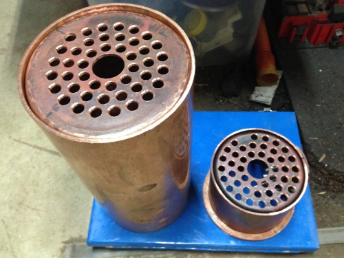
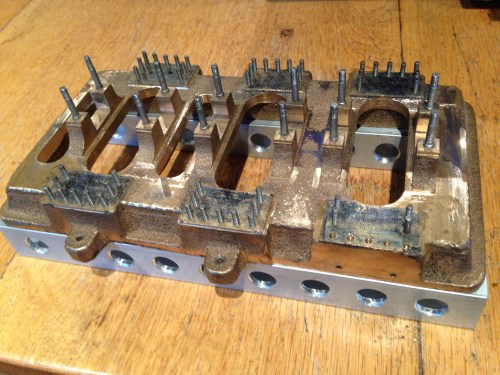
machines which I have made, am making, or intend to make, and some other stuff. If you find this site interesting, please leave a comment. I read every comment and respond to most. n.b. There is a list of my first 800 posts in my post of 17 June 2021, titled "800 Posts"
Today I drilled the girders of the chassis under the Armstrong cannon. Each girder has 91 rivet holes. Later I will need to drill more for the gear shafts, and for the center pivot bar.
The holes are 2mm diameter.
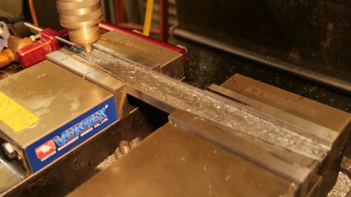
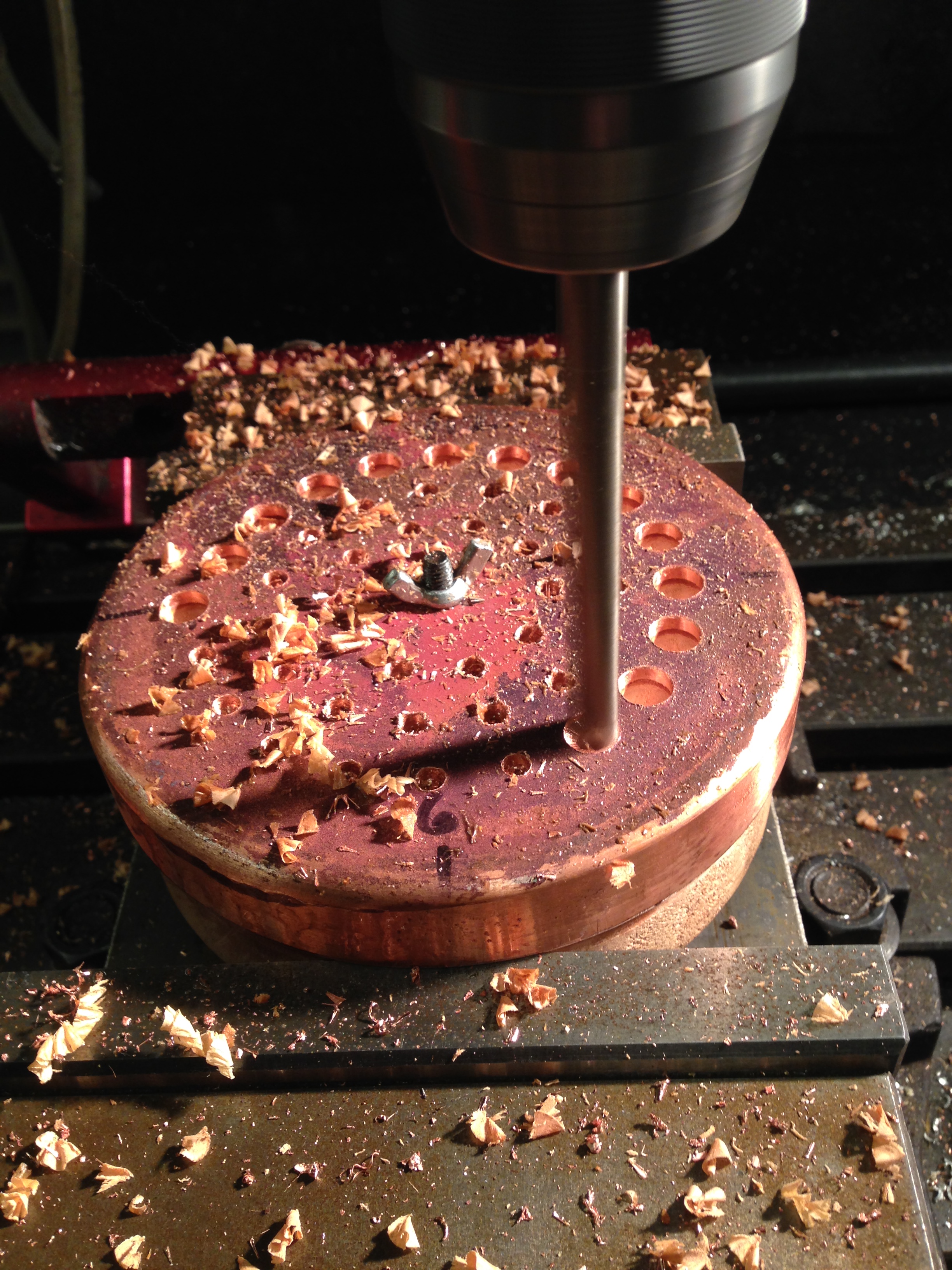
The mill drill setup. Re- indicating the vices again took me about 45″.
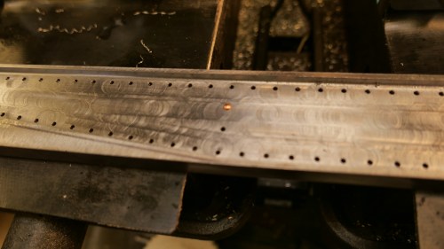
Firstly all of the holes were center drilled, then drilled through. The rivet confirmed a nice sliding fit.
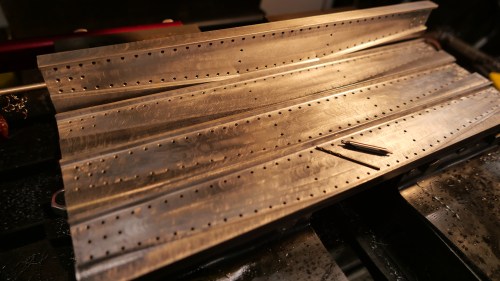
364 holes, through 5mm of steel done with one center drill, and one 2mm drill. That is pretty impressive IMO. More than 1.8 meters of steel with 2 drill bits. And using my olive oil and kerosene lubricant-coolant. And the bits still seem to be sharp.
Each girder took about 28″ to drill the 91 holes. CNC of course. It has been a while since I said it….. “I love CNC”.
After all of the careful flange forming I was careful to not screw up the firetube perforations in the boiler end plates. At times like this it is great to have a CNC mill/drill.
The wooden form is useful as a clamping aid.
No major stuff ups (or should it be “stuffs up”?). And I am not pointing out the small ones. I was unsure in the firebox plate which side to chamfer. Will I silver solder the top side or the bottom side? Eventually I decided that I would solder between the firetubes rather than the underside. Still unsure whether that was the best decision.
The “ligaments” (the metal between the holes) must not be less than 3mm. The minimum in these plates is 3.5mm. The holes are chamfered to make the silver soldering process easier. The extra hole in the top plate is to install the bronze bush for the attachment of the wet header.
Thinking about the options for a base for the triple expansion marine steam engine..
I looked at every photo I could find on the net, and thinking about whether I want to be historically accurate, or just really solid, or a bit interesting with an historical flavour.
At this stage, the decision is not set in concrete, but I am going with the last option. Photos later in this post.
But first, I have pulled all of the major components apart, and I am spending time doing a few of those jobs which I had been avoiding because they are difficult and imprecise, and if they go badly it will be a major disaster at this stage. Like drilling the oil holes and wells for the big ends.
Nothing precise about this. The con rods and big end shells and bearings have been painstakingly machined, and I do not want to think about remaking them if I stuff up. And drilling into curved surfaces, with a 1.5mm drill bit…
That thread is 3mm dia. The hole above the nut is the oil way, 1.5mm dia. Very tricky and too anxiety provoking to be thinking about a video. Amazingly, it all went well! I now have 2 oil holes for each of the 3 big ends. I will need to fill the well with oil with a medical syringe and fine needle, but.
The crankshaft, turned from stainless steel a year or two ago, and the conrods. The big ends now with lubrication points.
And here are the major engine components, after partial disassembly.
At top left is the condensor, then the cylinder block in 2 parts, then the steam supply valve. The square section tube is going to become the base. And so on. You get the picture. I will count the bits at some stage.
Then I cut and drilled the square section aluminium tube for the base.
The cast base of the triple, with main bearing studs and column studs in place. All sitting on the square section alu. Have not decided whether to bolt it together, or just Loctite it.
Those holes in the square section were drilled and chamfered on the CNC mill.
The next step in making the Stephenson’s link reversing mechanism, is to make the yokes for the links. See the previous blog. I decided to drill and tap the BA10 holes, while the bar stock was still rectangular, for ease and precision of clamping the pieces.
BA, in case you are not familiar, stands for British Association. BA threads were standardised in 1884, using imperial measurements (fractions of an inch), but to metric specifications. All very confusing. BA threads are rarely used these days. Model engineers, instrument makers, and restorers of ancient British cars and motor cycles being the exceptions. Builders of model engines often use them, because the bolt heads and nuts are nicely scaled for the models.
BA10 bolts are only 1.7mm diameter. If a BA10 nut falls on the floor, it is gone forever. I can barely see the thread of a BA10 bolt. I shudder to think of using the even smaller BA12’s.
The tapping drill is only 1.4mm diameter. A bit thicker than a human hair, (OK, many times thicker), but very delicate. And the holes needed to be at least 5mm deep. I do not possess a drill press capable of drilling such fine holes. Any run out of the chuck, or excessive pressure would just destroy the drill bit. Also, on working out the feeds and speeds of the drilling, it was apparent that the optimal drilling rpm’s would be 12,000 . Twelve thousand.
So, once again, CNC to the fore.
I reattached the high speed head to my CNC mill, worked out the XYZ co-ordinates, and did a practice run on some scrap. No problems! Worked like a charm. 12000 rpm and feed 100mm/min. Then to the actual job. Centre drilled all pieces. Then using the Pro-stop by Edge Technology vice stop, repositioned the work pieces and deep drilled them using the 1.4mm twist drill, using CNC peck drilling at 1.4mm intervals.
Then to tap the holes. The BA10 tap seems even more delicate than the 1.4mm drill.
I attempted to hand tap the holes, in the belief that holding the tapping handle in one hand, and the work piece in the other, would be the most sensitive system. But these hands, which once performed microsurgery, were not up to the job. It was inevitable that the tap would break in the job, so I abandoned the method before disaster struck.
The work piece was repositioned on the mill, again using the vice stop, and I used the CNC positioning to centre the tap fairly precisely squarely above the holes. I made a spring loaded point to apply light pressure to the tap, and to keep it centered. (see photo below). 24 holes and about 2 hours later the threading was completed. No breakages!
Tapping the BA10 thread. Note the Prostop vice stop, and the spring loaded centering tool.
BA10 bolts OK. Now to shape the yokes. (seen in the background.)
I had made a video of the CNC drilling, but the broadband downloading speeds here are so slow, that you will just have to imagine the excitement of the drilling.
OK, the video finally uploaded. It is pretty crappy. To see it, click on the link which follows.
Today I spent a couple of hours drawing CAD elevations of the high pressure cylinder steam passages, then generating some G codes for the CNC centre drilling, drilling, and tidying up of the steam passage connection to that cylinder.
Then I spent 30 minutes or so running the programmes.
All went well. No drill bits broken in the depths. No break throughs of dark passages into the cylinder bore, or into the bolt holes. Whew.
The steam passages now open into the top and base of the high pressure cylinder. Intermediate and low pressure cylinders to be done ? tomorrow.
This is the drilling setup. I used a sine vice, sitting on gauge blocks, to produce an exactly 5 degree angle, to avoid the cylinder bore and the bolt holes. The sine vice was held in the milling vice.
The 56 bolts which attach the cylinder heads, were installed today.
First, the heads were bolted into position with a jig.
The work is held in position on the milling machine table, using 4 hold downs, and 2 T slot locating fixtures. The jig also helps to secure the work to the table.
The jig fits into the milling machine T slot, and the bolts are exactly positioned in the centre of the heads.
The bolts hold the heads in place while the centre drilling, through drilling and thread tapping takes place.
That is 4 processes for each of the 56 holes. Even semi automating the process using CNC, it took 6 hours, including setting up, making the jig, and finally installing the bolts.
Drilling the relief holes in the heads, after preliminary centre drilling. Those holes are only 2.5mm diameter, and 12mm deep. Despite the tiny drill size there were no breakages. The drill was set at 2500 rpm, feed rate 50mm per minute, and with pecks set at 2mm. A cutting lubricant was used.
The head bolts in place. The bolts are BA7, which is pretty tiny, but they look the part, yes? The highest “density” of bolts is on the smallest cylinder head, which is on the high pressure cylinder. The threaded holes in the centre of the heads are for the pressure relief valves.
I have left the set up intact on the milling machine, until I am sure that there are no further processes I can perform with the block in this position.
To see the YouTube video, click on the link below. Sorry about the shaky image. I was holding my iphone in my right hand, while hovering my left hand over the emergency stop button, just in case. But it all went perfectly.
The triple expansion engine legs will be bolted to the base, with 9 bolts each. That is 54 holes which needed to be precisely drilled so the columns are accurately positioned. Each one of those holes needs to have a mating hole made in the base. The base hole will be threaded to accept a stud.
Normally one gets accurately mated holes by drilling through both objects simultaneously, but that was not possible in this situation due to obstruction from the columns themselves.
So the solution?? CNC of course!
The hole positions were known from the CAD drawings, and were entered into the CAM program. The resulting file was too big for my old CNC mill (1997 model), so I attempted to drip feed the information as the machining operation was taking place, but without success. Several phone calls to my expert friend Stuart did not resolve the problem, so Stuart kindly came to suss it out. A couple of hours later he had the drip feeding working as a result of a serendipitous error.
We knew that the largish file needed to be drip fed into the CNC mill, but it eventuated that we had to try to enter it directly, and produce an error message first, before drip feeding it. A bizarre system, originating from the land of Manuel of Faulty Towers.
A test run in scrap wood.
Heart in mouth, center drilling in progress
And 2.5mm through drilling
And the mirror image holes in the base. 2.05mm diameter, ready for BA7 threading. See how the holes line up exactly with the marking lines. Now to make 54 BA7 studs.
Deep drilling using CNC. The last hole was drilled manually, with problems. CNC rules OK!
A warm day today. Too hot to wear a shirt in the workshop. But no metal splinters from machining the brass and aluminium, and only one hiccup, which will be described.
The jig which I started yesterday, needed 9 more accurately positioned holes drilled and tapped M4.
So I programmed the CNC mill, only to discover that there is a limit of 8 holes able to be programmed. So the final hole would have to be separately positioned, and that was the cause of my problem.
Firstly, the 8 holes were deep drilled (30mm deep, 4mm diameter) after centre drilling. All done with the CNC.
All went beautifully. 2mm pecks, some cutting fluid brushed on.
Then I used the CNC to position the last hole, and centre drilled it manually, AND BROKE THE CENTRE DRILL IN THE JIG!!!
I did not want to remove the jig from the vice, because it was all accurately set up. But I could not see the broken high speed steel tip, so I removed the jig, and tried to dig out the broken tip. Unsuccesfully.
So the next method was to use an old carbide end mill, 4.5mm diameter, to drill into the hole and to break up the high speed steel fragment. That method worked, but at the cost of enlarging the accurately placed but incompletely drilled hole. Next step was to reposition the jig in the milling vice, then deeply countersink the hole, then complete the 4mm drilling operation. It seemed OK, but it later became obvious that the hole had moved about 0.5mm from where it was intended. I eventually used a carbide end mill to enlarge the entire hole, in the correct position, at 4.5mm diameter. All a bit messy, but not fatal.
The jig halves opened up, and the drilling positions which were entered into the CNC instructions.
Then the columns were drilled and tapped. 2 attachment points per column, so with 3 holes per column in the jig, there are 2 possible positions for each column in the jig.
The columns to be attached to the jig.
A column on the wedge in the milling vice, ready to be drilled and tapped.
The columns screwed to the jig.
2 columns are integrated with the condensing unit.
Re “Titanic” engine heading… I get a lot more hits on this blog if I include the word Titanic. OK?
Now that all columns are attached in their final position on the jig, I can start hacking into them to produce some flat surfaces
The columns sitting on the base in their correct position, using the jig.
LP is the column for the low pressure, biggest cylinder. HP is the column for the high pressure, smallest cylinder. IP is intermediate. C is for the steam condenser.
A day on the steam engine. SWMBO went to Melbourne to choose marble so I was free!!
After discussing my problems with machining the triple expansion engine columns with the senior members of the GSMEE (Geelong Society of Model and Experimental Engineers), I have machined a JIG to assist with this issue.
The JIG thickness is precisely the width between the columns (30.05mm). It is made in 2 halves so I can bolt the columns from their critical surfaces which are the con rod slides.
I will use the CNC mill to drill the holes in the jig, and the matching columns, then finish milling the columns which are attached to the JIG.
The jig for machining the columns. Not yet finished.
Bottom left is X=0, Y=0. The photo shows the 4 countersunk M4 screws.
The holes will be centre drilled then through drilled 4mm. The columns will be drilled 3.3mm then m4 tapped.
Hopefully that will happen tomorrow if the workshop is not too hot.
You will see what I am intending with the next post.