johnsmachines

machines which I have made, am making, or intend to make, and some other stuff. If you find this site interesting, please leave a comment. I read every comment and respond to most. n.b. There is a list of my first 800 posts in my post of 17 June 2021, titled "800 Posts"

Tag: CNC turning

Milling Machine handle -2

So, after my brush with a self induced limb avulsion on the CNC lathe yesterday, today I continued to make the handle to replace the one which I broke a few days ago.

Firstly I cut off the extraneous hex stock from the partly CNC turned handle so I could mount the piece closer to the 3 jaw chuck, thus reducing the distance between centers.

That substantially reduced the flexing of the workpiece and improved the surface finish.

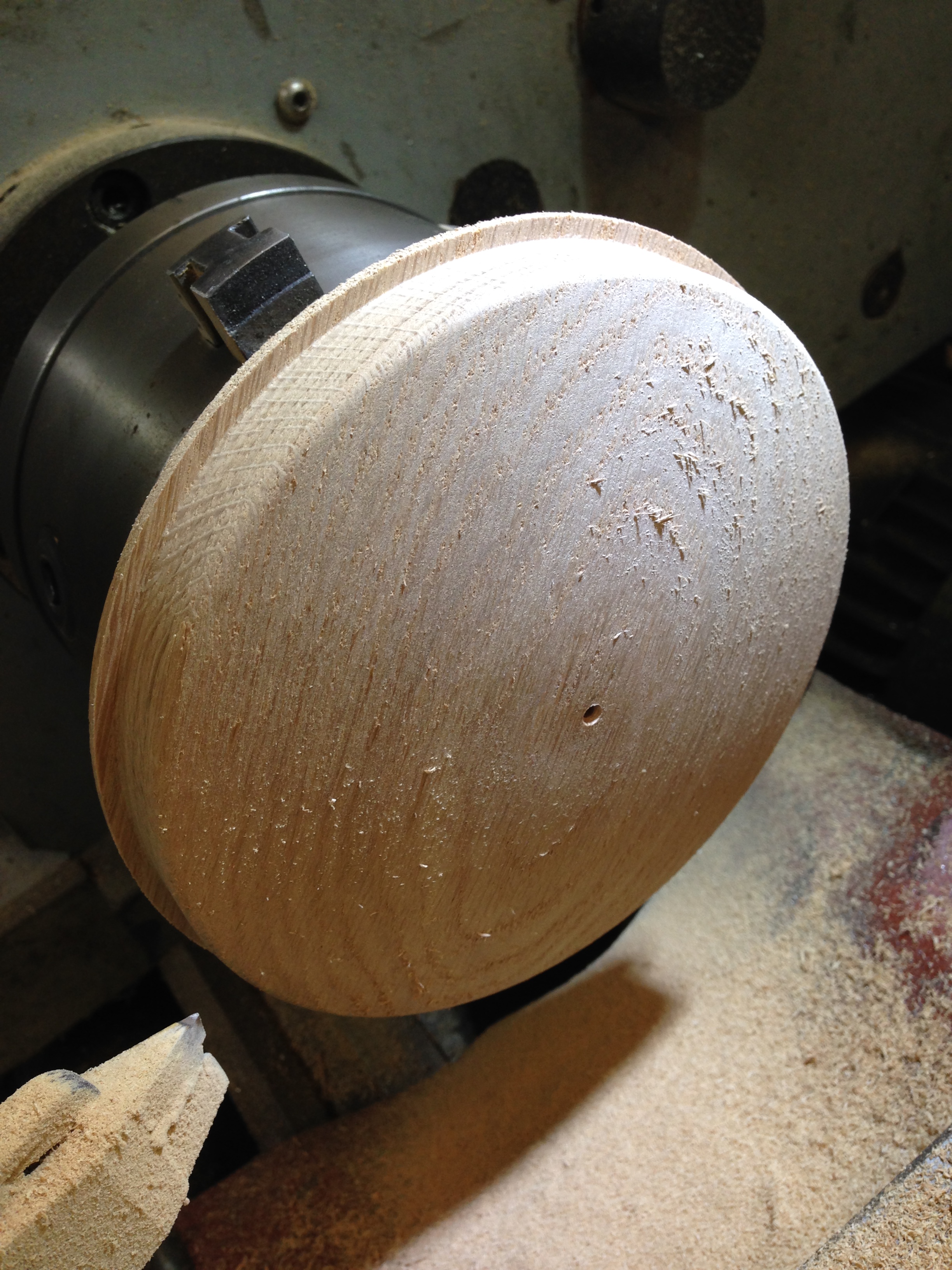
The photo above shows the improved mounting method, including a 3d printed spider. The tailstock has been moved to improve the photo. The CNC turning is finished.

Then I turned the hex stub into a 20mm shaft which could be held in my CNC rotary table on the mill.

I neglected to take any photos of that setup. On the mill I machined the flats on the handle, then drilled the 16mm and 8.0mm holes, and tapped a 3/8″ thread to attach the handle.

Finally used a 1/8″ broaching tool to make the slot for the key.

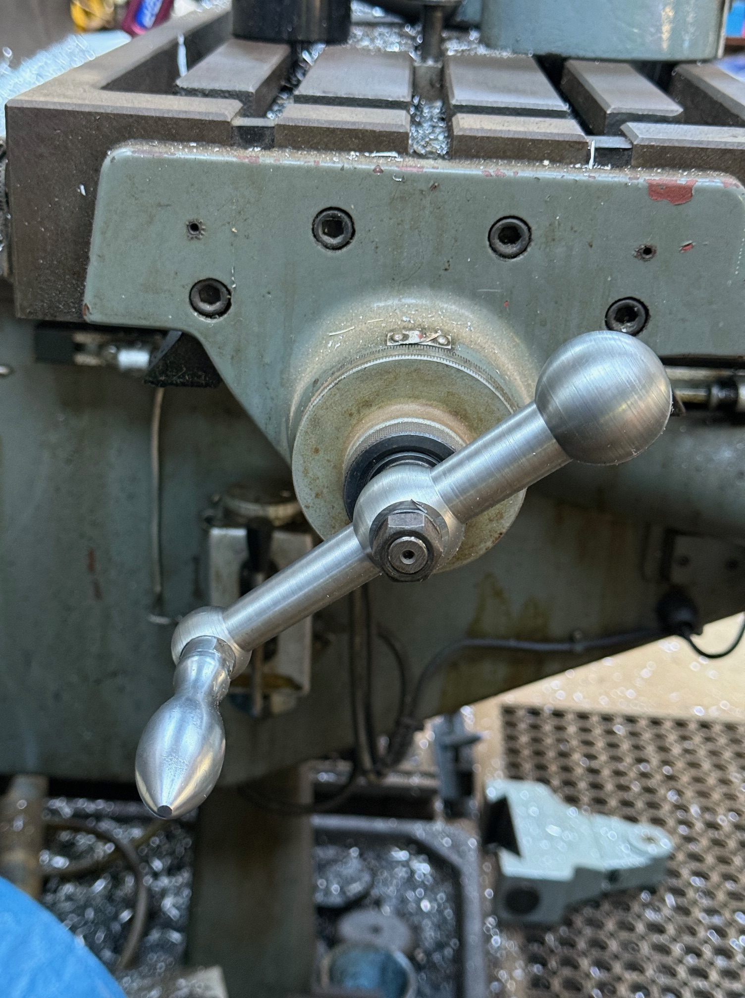
Then installed the handle on the mill.

The new handle in place. Works perfectly. Looks OK. Maybe needs to be chromed? Does anyone do chroming these days?

Trevithick Boiler End

The first part to be made for the Trevithick dredger engine is the domed end of the boiler.  It is formed from copper plate which is 3mm thick.  first a circle is marked out, then bandsawn from the copper plate.

I decided to make a wooden form.  Fortunately I have a CNC lathe (see earlier posts about the CNC conversion of a manual lathe), so drawing the profile and generating the G code using Ezilathe was, well, easy.

IMG_6390 2.JPG

CNC’ing the wooden form for the boiler end plate.  The roughing steps.  Carbide tip which has been sharpened to a cutting edge, suitable for wood.

Error
This video doesn’t exist

This is the final roughing cut, and starting the finishing cut.

IMG_6393 2.JPG

CNC turning.  Light sanding required to remove the fur.  The wood is European oak.  Central hole for a locating pin.

IMG_6416.JPG

The oak form was attached to a red gum block which was held in a 6″ vise.  I have already commenced shaping the copper disk here.  The copper is cramped to the oak form after annealing, and gradually hammered to shape.  Tapped rather than hammering.

IMG_6421.JPG

My “forge” is a few fire bricks in a steel shell, and a roof of steel to help retain the heat.  The torch is fuelled with propane.  It was originally a weed flamer, used to burn serrated tussock.

IMG_6424.JPG

Red heat was achieved in 90 seconds.  This is 600 degrees centigrade.  copper melts at 1084c, so there is a good safe margin.  I quenched to cool, for speed.

IMG_6419.JPG

This welder’s clamp proved to be the most effective method of holding the copper disk to the form.  I fitted  copper and  brass heads to the tapping hammer to minimise the chance of “bruising” the copper.

IMG_6426.JPG

Progress

IMG_6430.JPG

About 10-12 heating-hammering cycles in 1.5 hours to get to this stage.

IMG_6431.JPG

Getting close.  I will finish it tomorrow.  Might wash up before cooking dinner.

Making Hubcaps

IMG_5140

I made 5 of these

Hubcap blank.JPG

The 50mm diameter aluminium blank had a 12mm bolt inserted into a blind threaded hole.  The bolt was held in the lathe chuck.

The 2 short videos which follow show 1. the final rough cut 2. the finish cut.

The shape was drawn as a DXF file using CAD, the G code was generated using Ezilathe, and the lathe was controlled with Mach3.


Error
This video doesn’t exist


Error
This video doesn’t exist

Total CNC turning time was 16 minutes per hubcap, plus cutting the groove for the O-ring, then a quick polish with a cleaning pad.

Bombard Model. Turning the Breech


So if you watched the video, you can see that I have a problem with the big thread between the breech and the barrel, at least in the wooden prototype.  It might work better in brass or gunmetal.

The thread has a pitch of 6mm and a diameter of 60mm.   It is big.

My plan at this time, is to make a brass male threaded section, and glue or screw it into the breech.  Then to make a steel tap using the same G code, and cut a thread into the wood of the barrel.  (p.s.  note 30 Sep…  I continued to experiment with feeds, speeds, and cutter shapes in the wood.  The final result was OK so I did not make  metal threads.  That will have to wait until I do this project entirely in gunmetal or brass…  maybe never)