johnsmachines

machines which I have made, am making, or intend to make, and some other stuff. If you find this site interesting, please leave a comment. I read every comment and respond to most. n.b. There is a list of my first 800 posts in my post of 17 June 2021, titled "800 Posts"

Tag: Eccentric Engineering

Recovering from Friction Welding

Back to the model Armstrong cannon carriage this afternoon, and fitting 2 internal transoms, which provide rigidity to the carriage.

The transoms had been laser cut some months ago.  I cut the floor from 2.8mm stainless steel.

Each transom is attached to the sides and floor by angle iron, 2mm thick.  In the original cannons the angle iron was mitred at the corners, and for this model “A” carriage I decided to try to replicate the mitres.

The angle iron was again bandsawn from RSS tube and milled to 10x10mm.  I used the following setup to form the 45º angles…

P1074188

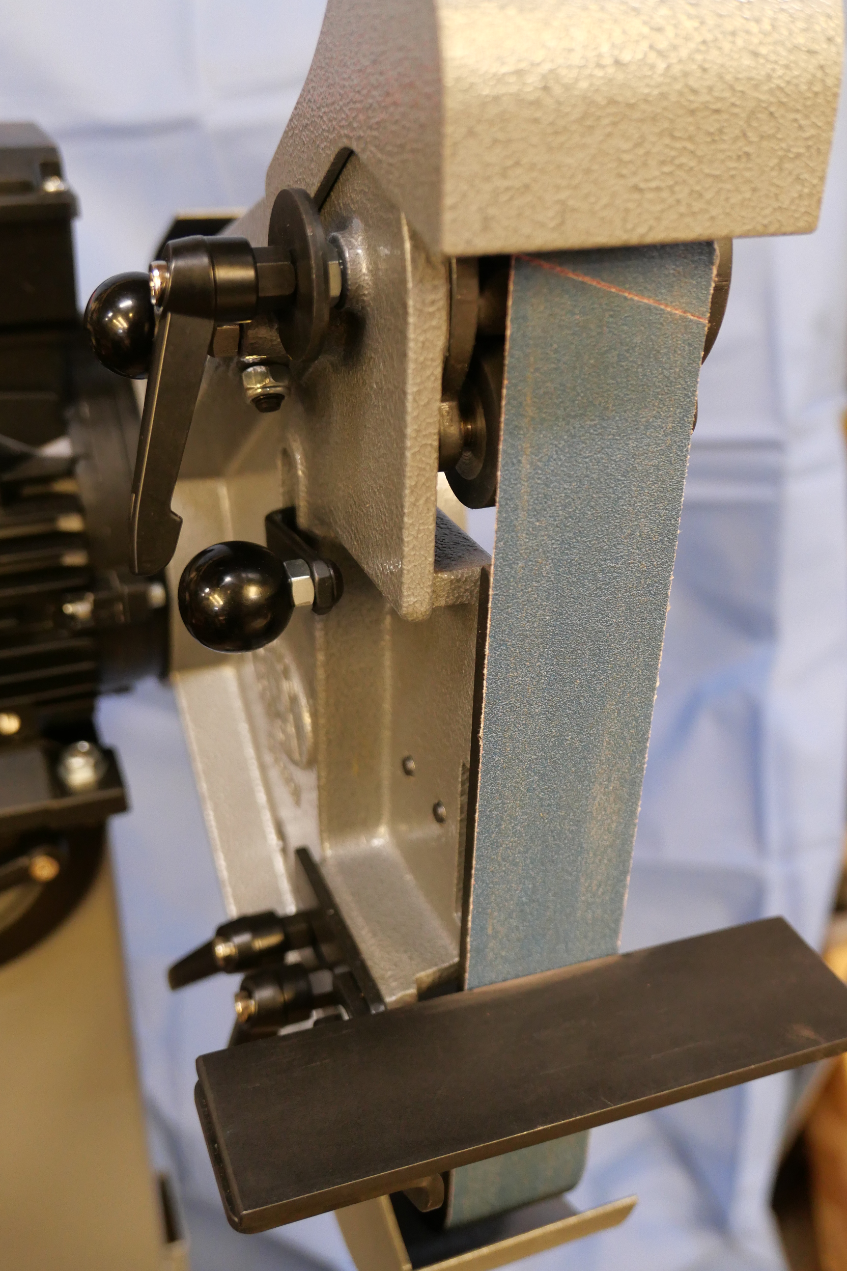
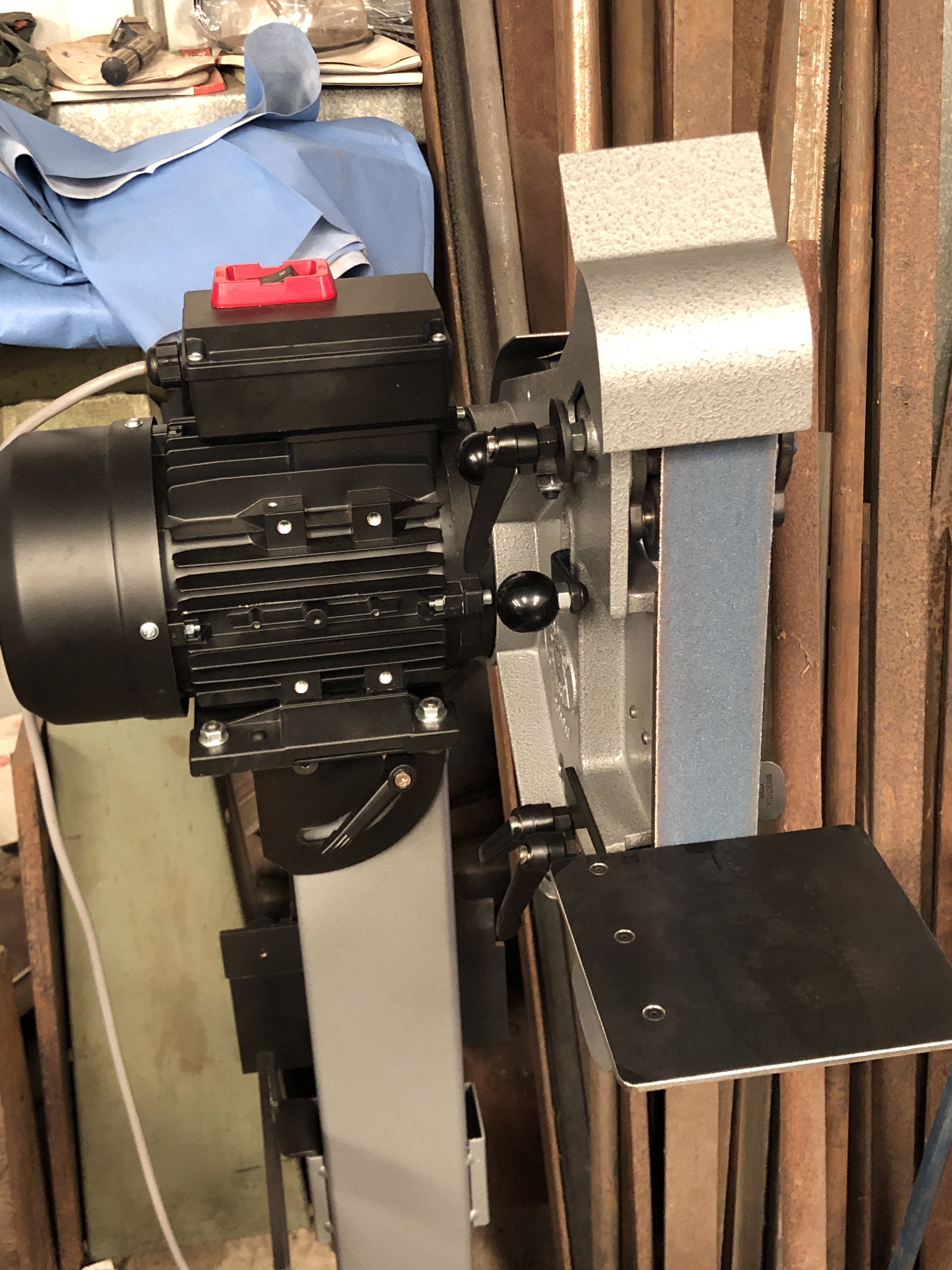
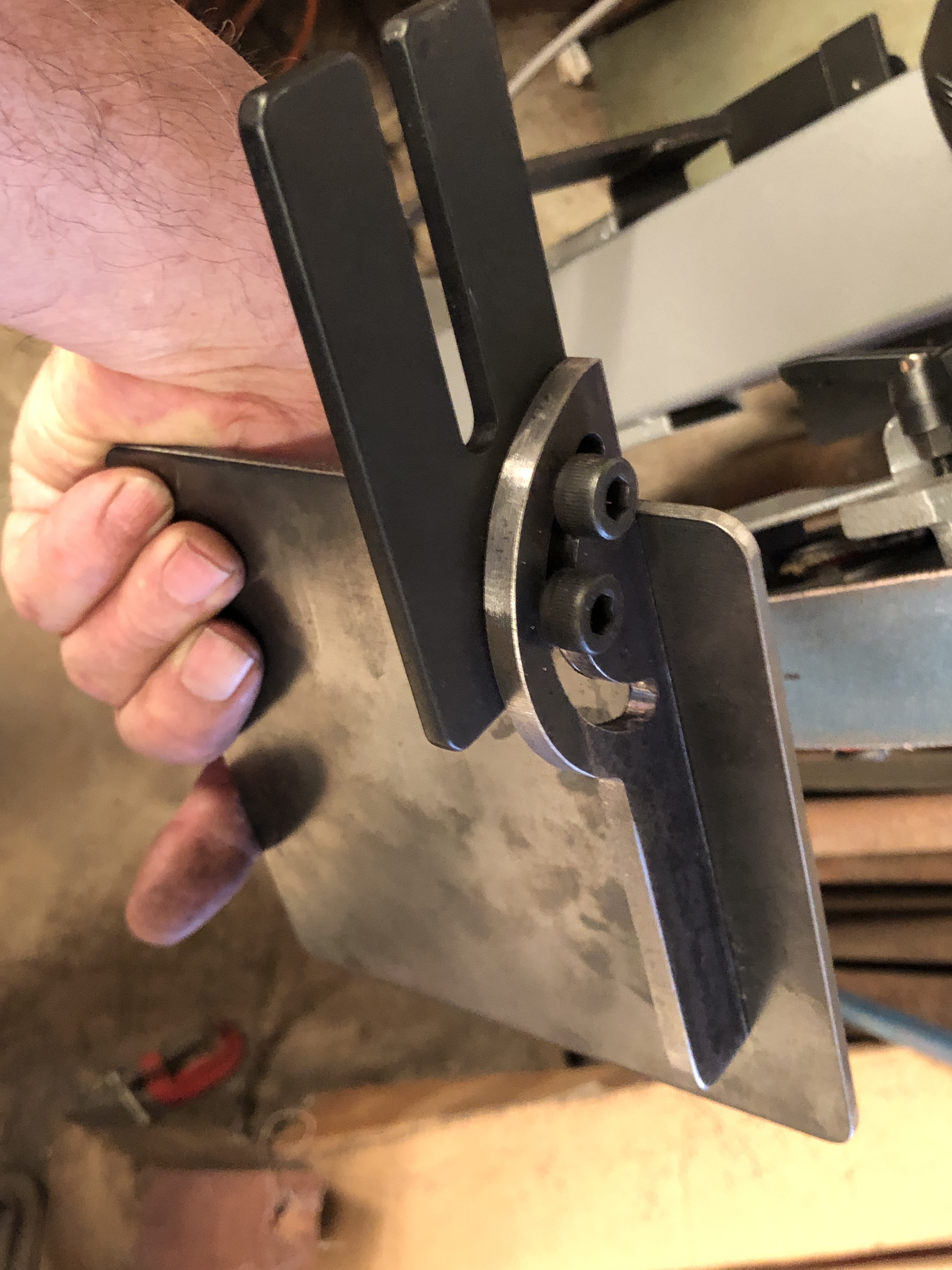
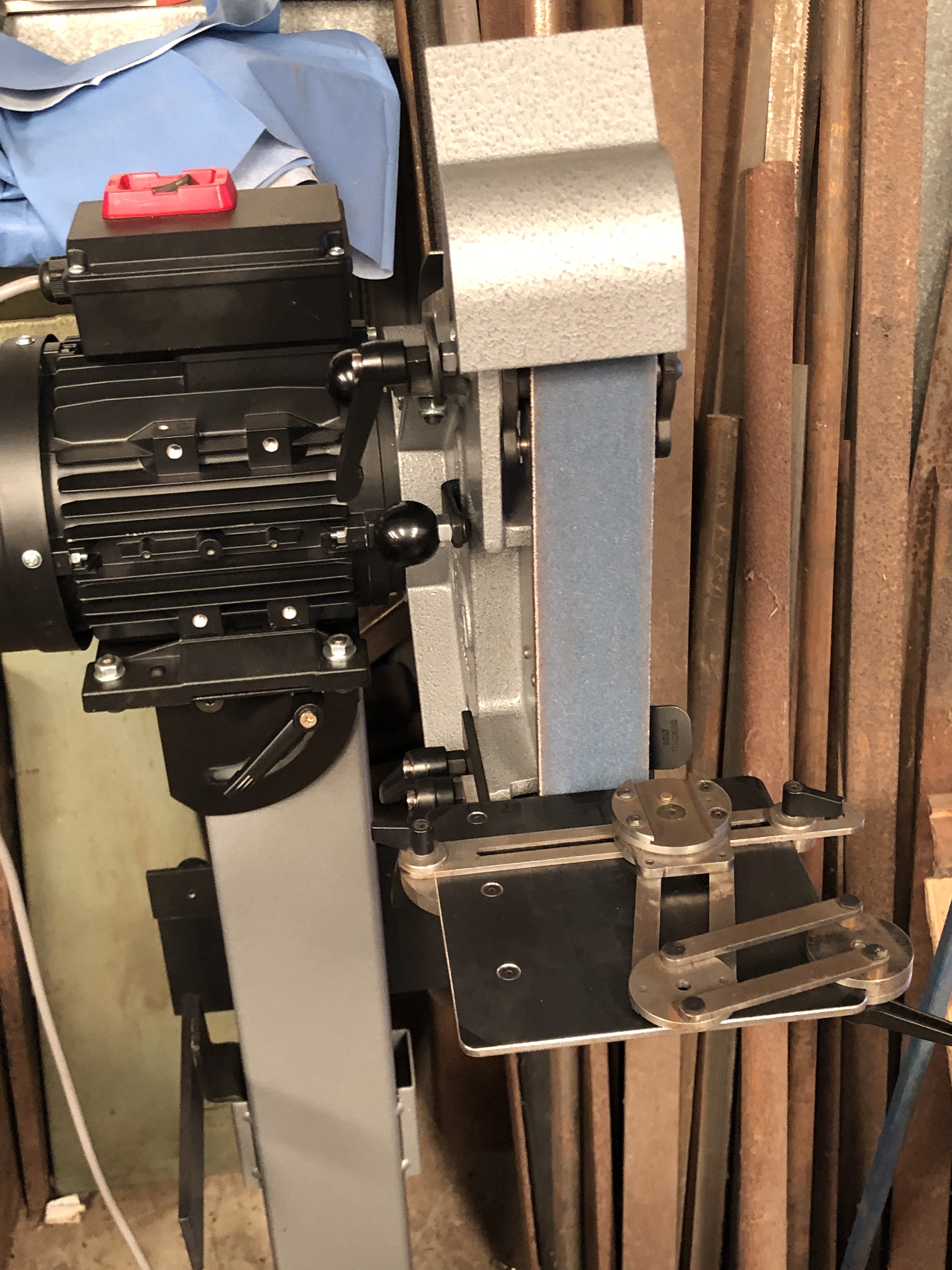
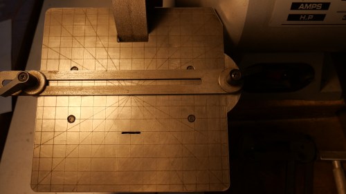
This is the Eccentric Engineering tool sharpening arm, set up to 45º on my RadiusMaster belt sander, about to form mitre angles on the angle iron resting to the right.

P1074193

The Angle iron pieces were glued to their respective transoms, and 2mm holes drilled.  Bolts progressively inserted.  The lengths and cutouts will be trimmed later.

P1074195

Then milled and filed the corners until the parts fitted neatly into the carriage.  Rivets will be inserted later.


…and for your interest/amusement, depending on your UFO opinion…  Listen to the information, and try to ignore the appearance of the narrator.


….and do I think that UFO’s are real?    I would say that my “belief” has risen from 95% to 99% YES.   One of my readers, with whom I have spoken directly, and for whom I have no doubts about personal veracity, has seen one at close quarters.  Do I think that they are of non human origin?  A bit less positive about that one, but it does seem more likely than not.  Waiting to see if and what NYT does publish.


A modification to the Radius Master

The Radius Master is a quality 48″ x 2″ belt sander which is impressively versatile with its 7 work stations.

The work station which is vertical, and against a platten is the one which I expect to use most often.

P1043100.JPG

Vertical belt, and using the backing platten.

But the supplied work – tool rest is a bit narrow for my taste, and I decided to make another one.

I really like the one which was supplied with the Acute Tool Sharpening System (ATSS).

P1043139

The Acute Tool Sharpening System from Eccentric Engineering.

So I bought some 4mm steel plate and cut it to size (150 x 150mm), and CNC milled a support bracket to fit the Radius Master.

IMG_8342.JPG

The Radius Master with larger work-tool rest.

IMG_8343.JPG

The rest is adjustable for angle and distance from the belt.  Copied from the original.  The bracket is screwed to the plate.  I did not want to risk heat distortion by welding the join.

Then the penny dropped.

Why not use all of the ATSS fittings and fixtures on the Radius Master?  So that is what I have done.

IMG_8344.JPG

The ATSS system looks quite at home, yes?

IMG_8345.JPG

Hey Gary Sneezby, maybe you should do a deal with Radius Master.

I can quickly swap the ATSS fittings and fixtures between the CBN grinding wheel and the Radius Master.  It will be interesting to see whether the cubic boron nitride wheel or the belt is preferred for different applications.  I expect that the belt will be best for quick removal of material and the CBN wheel for tool sharpening, but we will see.

Oh, and by the way, the bigger work plate does not interfere with any of the other work stations.

And I will ask my friend Stuart to laser engrave some guide lines on the plate.  I have a new design to try.

And finally, here is a link to the video of using the ATSS, by Eccentric Engineering.  It is worth considering.  If you have not done so, I suggest that you look at Eccentric Engineering’s other tools too.  They are very interesting.  The lathe parting tool is the best one which I have used.  And the Diamond lathe tool gets more use on my lathe than any other.


A Modification to the Acute Tool Sharpening System

I have several tool sharpening machines, including an industrial Macson 3 phase machine, a Harold Hall grinder rest, and a Quorn Tool and Cutter Grinder.

But, the one that I use most often is this Eccentric Engineering “Acute Sharpening System”. It was made from a kit and plans supplied by Eccentric Engineering.

P1043139.JPG

Photo 1: The Acute Tool Sharpening System (Photo courtesy of Eccentric Engineering)

The system consists of a table which is adjustable for tilt and height, a work arm consisting of parallel links and a work head, a straight arm which is adjustable for position and angle and which the work head will slide along, and various fittings for holding lathe tools, ER collets, and others.

P1043149.JPG

Photo 2: My ATSS. The ATSS with cubic boron nitride wheel on the LHS, and the elegant but less frequently used Harold Hall grinder rest with diamond cup wheel on the RHS.

I purchased the kit of laser cut and spotted parts and the excellent 32 page bound plans from Eccentric Engineering. The parts in the kit require final machining, including drilling, reaming, tapping, turning and milling. It would be quite possible to use bar stock for the parts, having purchased the plans, but the kit is good value ($AUD 250 + GST) and it made the job quick and straightforward. A completely machined, assembled system is also available.  Details at https://eccentricengineering.com.au.

P1043141.JPG

Photo 3 These are the fittings which I made from the kit, and some extra parts which I bought later.

From the left: hex keys for quick adjustments, angle and gauge templates – most bought from Eccentric, but some made by me, tool holder centre, and collets on the right. Some of the collets are blank to be machined as required. Top right is an ER collet chuck.

P1043143.JPG

Photo 4 This collet holds a 6mm lathe tool.

This post was not really intended as free publicity for Eccentric, although I am very happy to give it a good rap. It is actually to show a modification which I made to the ATSS table. Shown in the next photos…

P1043147.JPG
My colleague Stuart Tankard recently acquired a CNC laser engraver which will engrave steel and brass and cut thin metal. I thought that it would be useful to have some accurate lines on the table in a grid, and others at angles to assist with setups. The grids are at 10mm intervals, and the angles are 30/45/60 degrees. In the above photo the straight slide is easily set parallel with the wheel face.

Of course, the cubic boron nitride wheel must first be accurately set to the table, and the grid assists with that….

P1043140.JPG

Photo 5 Straight edge lined up with the wheel edges and grid.


P1043145.JPG

Photo 6 And here the tool holder base is set at 60º to the wheel.

The angle gauges supplied by Eccentric will serve the same function.  Time will tell if the table marks are useful.

Also I am thinking that the work table on the RadiusMaster could use similar guide lines!

Triple Expansion Steam Engine -The water pump

john and audrey - 5.jpg

The triple will not be finished by Xmas.  No chance of getting into the workshop while we are looking after 2 grandchildren.  So the new aiming completion date is Jan 6, in time to run the triple on steam at the Geelong truck show.   If I don’t meet that deadline, the next access to steam will be the end of 2017.  I really do not want to wait that long.

So the next component to produce out of a chunk of gunmetal is the water pump.

triple-expansion-engine-1-18

There are two cylinders in the water pump.  The gunmetal castings appear to be good quality.

Most of the machining will be done on the mill.  But I need a datum surface, and have decided that the attachment plate is the most appropriate.

triple expansion engine - 1 (20).jpg

I do not need the small cylindrical protruberance, but that chunk of gunmetal might be handy for something else (eg as a bushing), so I parted it off and saved it.  Lovely parting tool is from Eccentric Engineering.

triple-expansion-engine-1-17

Then turned a flat surface.  On the mill I machined it to a rectangle.   Diamond tool is also from Eccentric Engineering.

triple expansion engine - 1 (21).jpg

The two water pump cylinders are bolted to the air pump.  BA7.  A broken tap is entombed in the air pump forever.

triple-expansion-engine-1-22

When I get back into the workshop I will machine the rest of the pump parts.

A Collet Chuck for the Colchester Lathe

I recently bought a blank chuck backing plate on Ebay, hoping that it would fit my Colchester lathe.  It was $AUD110 plus postage, which, if suitable, would be an excellent price, but it was a gamble.  It was old new stock.

When it arrived I cleaned off the old, hard grease, and nervously presented the backing blank  to the lathe headstock.  It fitted perfectly!  The seller had another identical blank backing plate, so I bought that one too.  Components for the Colchester are not readily available, so I was very happy with this find.

I had a use in mind for both of the backing plates, and a few days ago I machined up the first one as per the following photos.


IMG_3330.jpg

The cast iron backing plate blank had a tough skin which a high speed steel cutter would not penetrate. So I use a carbide insert tool cutting 1mm deep to break through the skin. I finished the contact surface with a HSS tangential tool. (A diamond cutter from Eccentric Engineering)


IMG_3331.jpg

The C5 collet chuck.  I have had this chuck for a few years, purchased from CDCO Machinery (USA), but rarely used it because I was not satisfied with the accuracy.  I was very interested to see whether a very careful installation on the Colchester lathe might be more satisfactory than on the previous lathe (a Chinese lathe).  


IMG_3332

Checking the runout off the newly installed collet chuck. With a piece of 10mm diameter silver steel, the total measured runout was about 0.005mm. Good enough.  The backing plate is larger than required, but I will leave it as is in case I ever use it for another, larger chuck.   C5 collets will hold round stock 2-26mm diameter, and some common square and hexagonal sizes.   Very useful.

ACUTE TOOL SHARPENING at GEELONG MODEL ENGINEERS’ EXHIBITION

One of the tool displays at our exhibition last weekend (see previous post) was by ECCENTRIC ENGINEERING.  Eccentric Engineering is well known for the Diamond Tool Holder, which is a favourite lathe tool holder for most of us who use metal working lathes.

However I was more interested in Gary Sneezby’s (Owner-engineer of Eccentric) new tool, which is a tool sharpening system for use with a bench grinder, named “The Acute Tool Sharpening System”.

IMG_3305

Gary demonstrating the Acute Tool Sharpening System at the GSMEE exhibition.


IMG_3319

The Plans and assembly diagrams, in a bound booklet.

The system is available as a complete working unit, or a kit of semi machined parts and plans, or plans only.

See the Eccentric Engineering Website for a complete description of the system and prices.  eccentricengineering.com.au

I bought the kit of semi machined parts, and the booklet of plans.  Cost (show price, no postage) $AUD250.  This is an excellent price for the 50 or so laser cut parts, quality die cast handles, all fasteners, Allen keys, detailed plans.


IMG_3321

2 of the 33 pages of plans and diagrams.

The plans are excellent.  They are clear, easily read, and large.  There are no instructions, but a DVD is planned.  Gary is contactable by phone for construction advice, if needed.

After 4 half day workshop sessions I am well into the construction.  The laser cut parts are accurate within 1mm, and drilling points are accurately centre drilled.  Gary pointed out that the drilling points are more accurately positioned than the laser cut part perimeters.  That necessitates drilling centre holes (and the other holes) and using a mandrel to enable accurate turning of circular components.  He also advised that HSS cutters be used in preference to carbide tipped tools.

I found the parts to be very closely dimensioned to the finished parts.  The table top measures 150x150mm, and I found the flat hardened steel to be mildly bowed, to the extent of 0.38mm.  That is probably due to heat distortion from the laser cutter.      Some attention on the press straightened out the plate to less than 0.05mm bowing.   I might touch it up on the surface grinder, but that is probably unnecessary, given the way the system functions.

I had a machining accident with one part.  It is useable, but will need to be replaced.  I rang Gary, and the new part is in the mail.  Now that is service.

Progress to date….

IMG_3326

The sharpening system is starting to look serious.  It consists of a base, top plate which is adjustable for tilt and height, parallelogram arm, slide and toolholder.


IMG_3323

It looks interesting. Not sure how it works yet (Much clearer since watching the YouTube video at the end of this blog). Still some parts to be made-machined. The notch at the top is where the grinding wheel fits.


IMG_3322

The underside. Nice use of O rings to lock the adjustments into position. The cast handles are good quality.


Another session or two in the workshop should see this project completed.  I will report on how it performs  in a week or two.  I expect that it will be a lot quicker and simpler to use than the Quorn.

Watch the YouTube video by Gary to see how it works.

CON RODS for TRIPLE -2

The con rod shafts have a taper of approx 1.5 degrees.  I turned the shafts between centres, using a tangential tool. The HSS cutter has a round cross section which gives a good finish, and automatically fillets the joins.

The con rod shafts have a taper of approx 1.5 degrees. I turned the shafts between centres, using a tangential tool.(a Diamond tool holder from Eccentric Engineering).  The HSS cutter has a round cross section which gives a good finish, and automatically fillets the joins.

IMG_2673

Of course left and right hand tools are required to do the whole taper.

Another jig! The con rod is difficult to hold accurately for milling, so I made a jig to assist. 10mm aluminium plate, with a cut out section to accept the con rod casting.

Another jig!
The con rod casting is difficult to hold accurately for milling, so I made a jig to assist.
10mm aluminium plate, with a cut out section to accept the con rod casting.

IMG_2675

The jig had to be made as accurately as possible. So it was milled square and parallel, then centre pins were installed to hold the casting by the previously drilled centres. A further pin with a sharp point was installed to stop the casting from rotating during the drilling and reaming for the gudgeon pin. That gudgeon pin hole was continued through the jig, so a large pin could be inserted to really hold the casting securely. It also allowed an accurate 180 degree rotation of the casting.

IMG_2676

A bit clearer with the swarf swept away!

IMG_2677

You can see the gudgeon pin in place, while further surfaces are milled.

IMG_2678

Close up of the jig and my metal workers’ dirty hand.   Just as well there is no more gynaecology.

IMG_2679

Progress!

IMG_2680

Not a clear shot, but here I am using the flutes of a milling bit to smooth the flat section under the gudgeon pin. Not ideal but it worked OK.  Tomorrow I plan to round off the external surfaces and mill the slot for the cross head.    Not much to show for a full day in the workshop, but it was fun…