No Wobble Flywheel

Subscribe to continue reading
Subscribe to get access to the rest of this post and other subscriber-only content.

Subscribe to get access to the rest of this post and other subscriber-only content.
Yes. As usual, this project has taken at least twice as long as I had planned.
But, the making of the crankshaft has finished, and I have started to install it in the traction engine.
I installed the valve eccentrics, approximately in their correct positions. I had marked the eccentrics according to their position on the old crankshaft. The exact timing positions will be determined when everything is installed.
The crankshaft was placed in the main bearings. I had made the crankshaft with the bearing spacings according to the original plans. Then realized that the original maker had varied some of the dimensions, including the distance between main bearings. So I needed to gain approx 2mm between the main bearings. I achieved that by taking some width off one of the gears on the lathe.
Today, I started to fit the big end bearings. I had deliberately made the big end journals 0.1-0.2mm bigger than the old ones, knowing that I would have to increase the diameter of the big end bearings.

The 3 jaw chuck is holding a smaller independent 4 jaw (because I did not have a suitable backing plate for the small 4 jaw. And I needed a small 4 jaw so the bearing halves would seat on it.). The big end bearing is held in its engine housing, and the original bearing hole was clocked in the 4 jaw as accurately as possible, after tapping it against the jaws with a light hammer. Then the bearing was turned to the slightly larger diameter.

The crankshaft with the main bearings and big end bearings tightened. The eccentric rods are held out of the way with aluminium wire. The shaft turns but it is very tight, and will need further freeing. I have used some “Gumption” but it needs a bit more. Maybe running the engine on compressed air will free it up.
A quick test with the flywheel in position looked promising in terms of run out.
Finish turned the big end journals today. I decided to make them slightly bigger than the original shaft, because there was a measured deficiency of approximately 0.1mm – 0.15mm (? wear, ? manufacturing error) between the original shaft and the original split bearings.
I had rough milled one of the big end journals a couple of days ago, and Loctited a block into the crank slot of the other big end. I decided to finish turn that journal first, then to remove the loctited block and glue it into the finished crank slot, before rough milling then finish turning the second big end journal. If you follow me.
That all took another half day. And, I experienced my first significant (but not fatal) stuff up in the job.
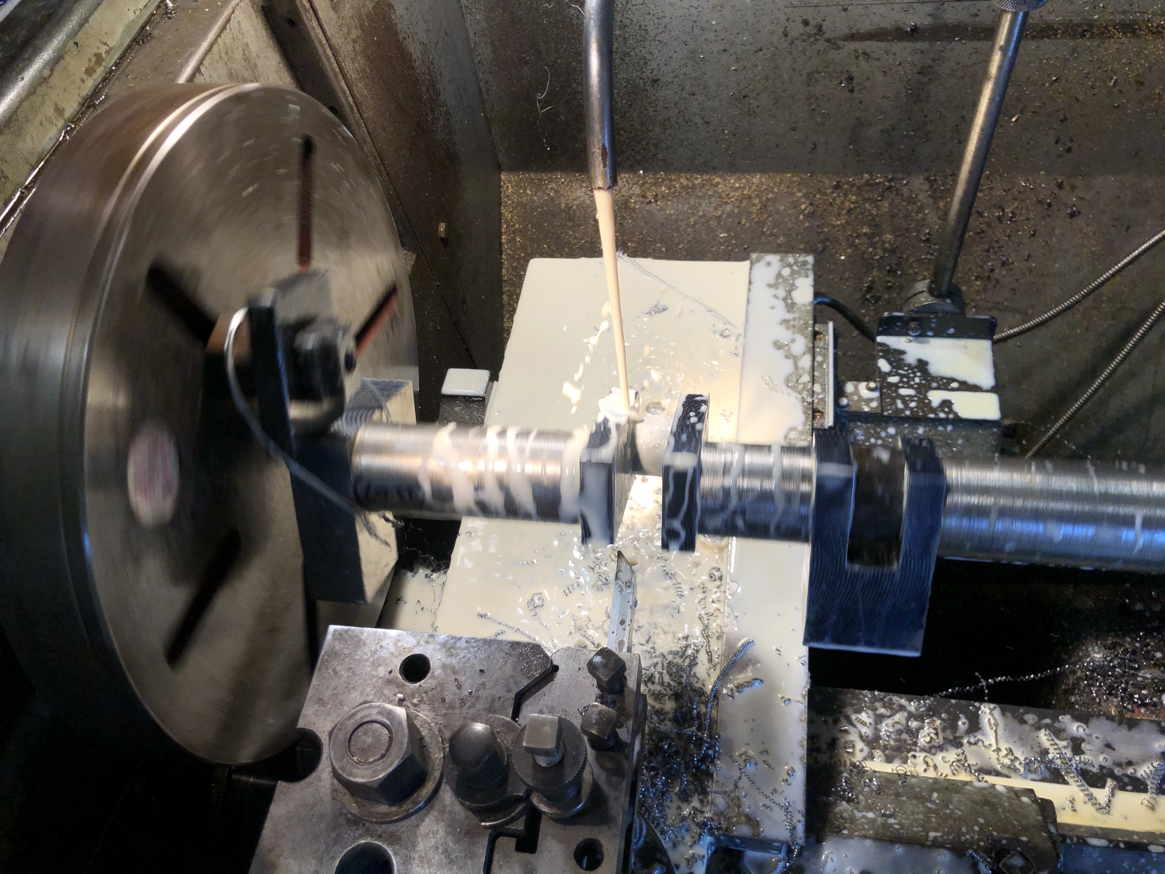
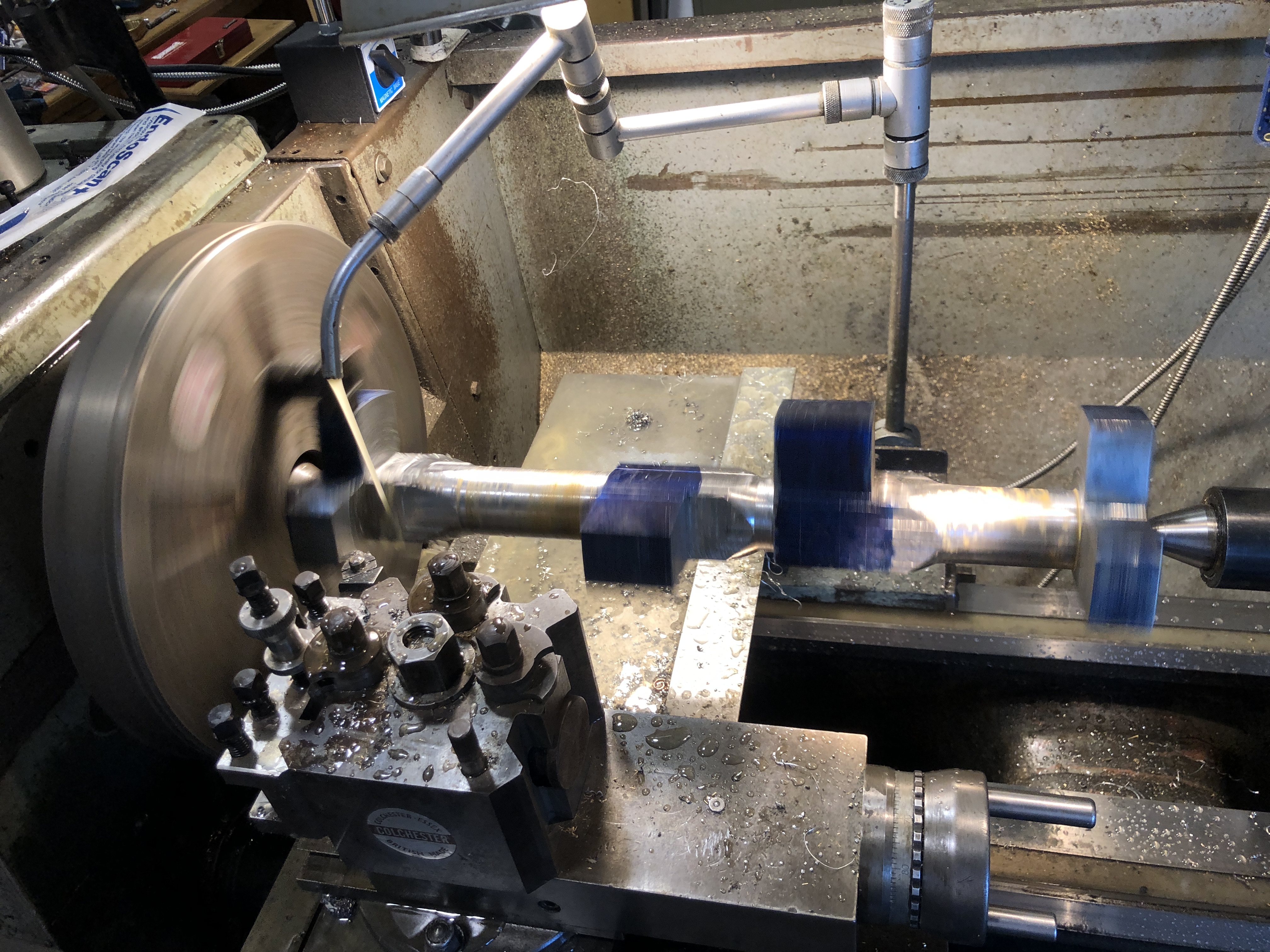
Copious coolant, 135rpm. Of course the workpiece is centered on the big end journal. Here the tool is approaching the journal to be machined. The packing piece is glued into the other crank slot, and will remain there until the journal being machined is totally finished.

After finishing the first journal and changing the location of the packing piece the second journal was roughed out on the mill. I was much more confident about this method by now, and was more aggressive with the cuts. Used coolant throughout, and the cutter was in good shape at the end. I roughed the diameter to within 1 mm of the final dimension to reduce the time for finish turning. Note the use of my shop made clamp to reduce backlash and vibration. That worked much better than the previous soft wire method.
When I was happy that the journals were finished, I glued in a second packing block, centered the shaft, and turned the curved outside shape on the crank flanges.
Oh yes. The stuffup. After one side of the first journal was turned the insert was blunted, so I rotated the insert. But unfortunately dropped it and chipped it, so it was replaced with a new one. My error was that I did not notice that the tip radius of the new insert was different… 0.8mm radius rather than the original which was larger and made a nice fillet at the join (see above photo). The new insert made a much sharper join, still with a radius, but much sharper. Not fatal, but not ideal.
In the next session I will recheck all of the big end journal measurements. If all are good I will cut off the side flanges at the ends of the shaft, removing those centers for ever.
I will see if my fixed lathe steady will fit into the middle gap between the cranks. If it fits, I will take a smooth light lathe cut of that section and install the steady. Then finish turn both outside sections of the mainshaft. Then move the fixed lathe steady to one of those outside ends, and finish turn the central section. The central section is where the eccentrics are located.
If the fixed steady does not fit in the middle section I will finish turn that section first, after installing the fixed steady on the longest outside section of the mainshaft.
Those possibilities are to keep the mainshaft as rigid as possible during all of those turning steps. (that list is more for my benefit than yours, dear reader).
p.s. So far, there has been no discernable distortion of the workpiece despite removal of over 20kg of swarf. That has been assessed on a granite surface plate, after filing all of the machined edges of all metal tags and lips.
Another workshop session. About 5 hours today. That is about my limit before I need to put my feet up.
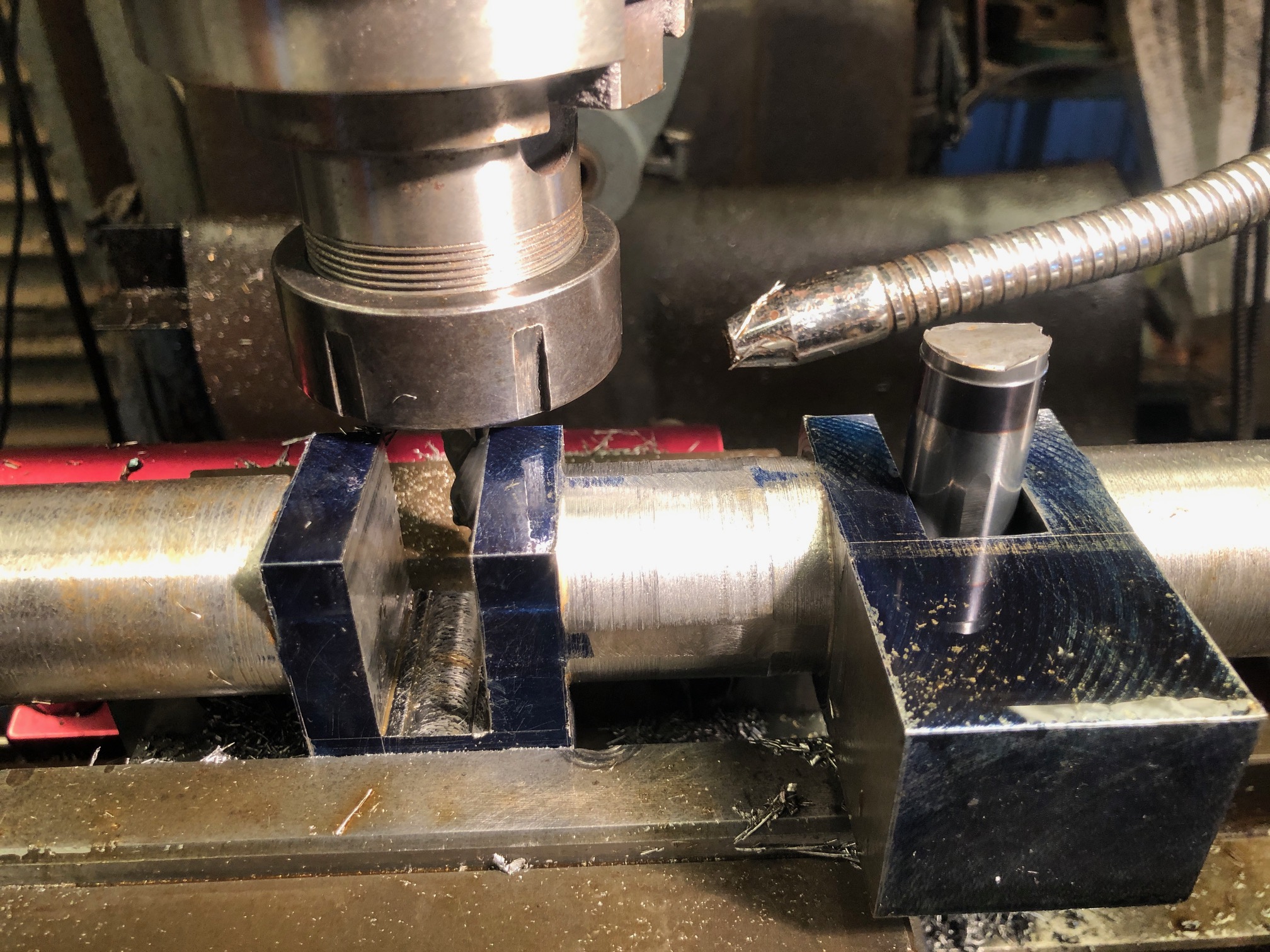
Today I hacked into the solid heavy strong shaft, to form the crank web slots.

The carbide cutter was 12.7mm diameter, and flood coolant was used. Each cut was 2.5mm deep.


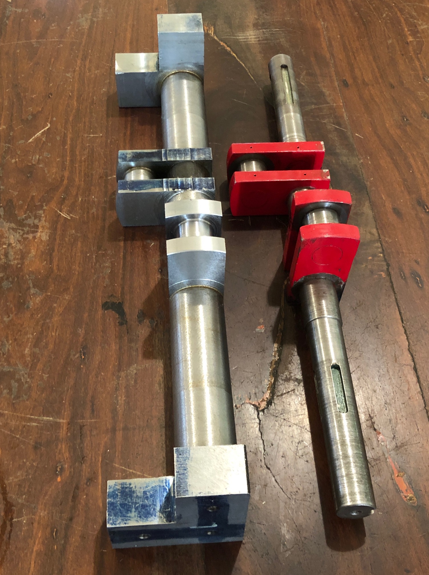
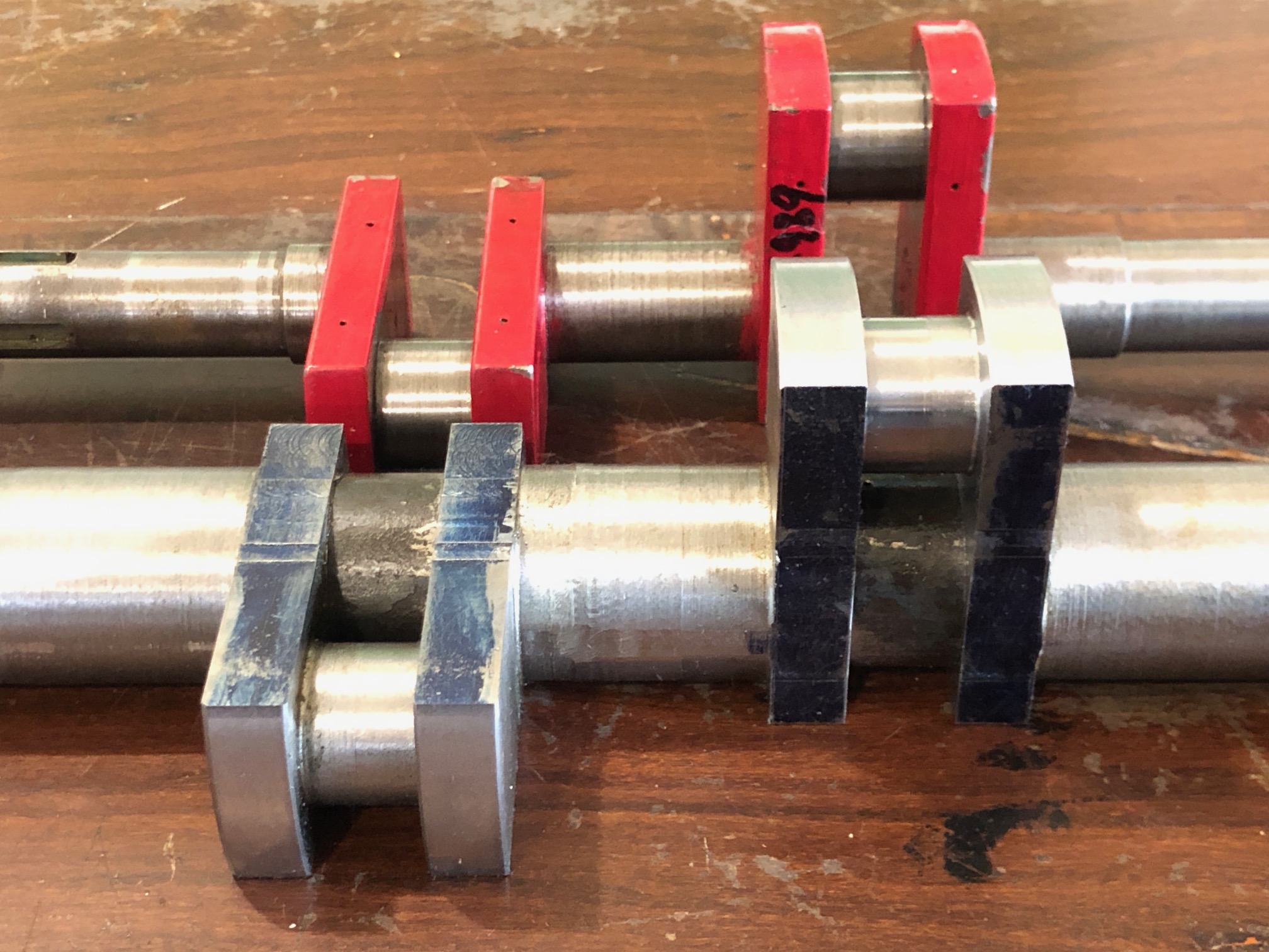
So parted off x2 19mm buttons from some 36mm shaft. They slide into the gaps, and will be loctited in place when necessary.
Finally for today I measured the big end bearings, main bearings, eccentric holes, and mechanical water pump eccentric hole. The bearing holes were all approximately 0.2mm larger than the old shaft size, probably due to wear. They are all close to round, rather than oval. So Intend to machine the new shaft to match the largest diameter of the bearings. If necessary I will ream the old bearings to match the new shaft with a circular shape.
I am a bit apprehensive about turning the big end journals because the work piece will be severely unbalanced. Obviously I will install some balancing weights on the lathe face plate, but then there is the situation of the long stick out length of the turning tool, about 40mm. I am pondering the possibility of using the motorised CNC rotary table to very slowly rotate the workpiece, while converting the square sections to cylinders on the vertical mill. Then finishing the journals on the lathe. Hmm. Might just work.
This is the moment when I allow myself to envy the owners of 5 axis CNC mills, in which a crankshaft is made in the duration of a YouTube video, with perfect results, no mess, just a bit of expert CNC programming. But then… if it was that easy, everyone would be doing it.
You might be wondering why I am posting these updates after each workshop session. Partly it is so the day’s activities are recorded while still fresh in my mind. But it is also my method of keeping a diary, for possible future reference, in case I ever have to make another crankshaft (like for another triple expansion steam engine?).
Another half day workshop session.
I decided, after advice from several readers, to rough turn the mainshaft.
But first, just in case you were wondering, the kitchen entry stairs are finished, except for a bit of painting.

But just in case kitchen stairs are not your thing, back to the Fowler R3 traction engine crankshaft ….
Today I rough turned the mainshaft.
First I tested and adjusted the tailstock offset.

Then mounted the crankshaft blank between pre-drilled centres…

And turning towards the headstock. This was interrupted turning +++. I took 1mm off the diameter, then as I became adjusted to the machine gun rat-a – tat-tat, gradually increased the depth of cut to 1mm, with a spindle RPM of 175/min. Later I added coolant. Note, I used a ball bearing tailstock centre for the rough turning. I will use a solid centre for the finish diameters.
I was not too fussed about actual dimensions. They were roughing cuts, and at 38mm diameter there is plenty of extra material. It should be much smoother machining to reduce the diameters of the cylinders, compared to rounding the square sections.

After getting quite a few opinions about stress relieving the workpiece, after all of this machining, I have decided to take the workpiece up to 600deg c, for 1.5 hours, then slowly cool. Probably unnecessary, since it is black steel, but it can’t hurt. Then I will do the final dimension turning.
p.s. about a week later. No detectable movement despite a lot more material removed. And some further expert advice that heat treatment might actually cause problems. So, given the controversy I have decided to do nothing. ie. No heat treatment.
