johnsmachines

machines which I have made, am making, or intend to make, and some other stuff. If you find this site interesting, please leave a comment. I read every comment and respond to most. n.b. There is a list of my first 800 posts in my post of 17 June 2021, titled "800 Posts"

Tag: Jerry Howell

A Matter of Scale

Before I get onto a brief reflection about scale, the photo below shows 2 cannon barrels.

The big one was what impelled me to converting a manual lathe into a CNC lathe.  That time consuming, costly, and ultimately very satisfying project, started because the CNC lathe which I used to turn the big barrel could only handle the job by doing it in two stages…. doing the breech first then the muzzle.  That was due to the big barrel being too long for the lathe, at 300mm (12″).

The small barrel was a test for the CNC converted lathe just finished, being the first complicated shape which I have made.   To save on material, I made it at exactly half the scale of the big one, ie 150mm long (6″).

IMG_4291.JPG

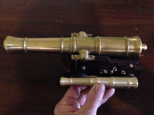
Comparing the two barrels reminded me, that if an object is twice as big as another, in all 3 dimensions (height, width, depth), it is 8 times as heavy.   And any projectile, and weight of black powder, would also be 8 times the weight.  But the wall thickness of the explosion chamber is only TWICE as thick.

My point is, that if scale is maintained, the smaller the cannon, steam engine, boiler, whatever…..  the less likely it is to explode.

Not that these cannons will ever be fired.  Just hypothetically.

1779 Naval Cannon Scale Model

It is almost 2 months ago that I started this model.

I thought that it would take 3 or 4 days!

Anyway, here it is.

It will look interesting on the mantelpiece.

cannon - 3.jpg

Note the hinge and square bolts and keys on the trunnion straps.

cannon - 4.jpg

A good view of the elevating apparatus, the quoin.

cannon - 6.jpg

A trunnion, trunnion band, trunnion bolts and key.

cannon - 7.jpg

Powder pan and touch hole.

cannon - 8.jpg

The underbelly

cannon - 2.jpg

It goes on display at the Geelong Wooden Boats Show next weekend.


Cannon trunnion shoulders, flash pan and trunnion brackets.

Another couple of long and very enjoyable workshop days, making various bits for the 1779 24 pounder model naval cannon.

cannon - 23.jpg

cannon - 5.jpg

The trunnion shoulders were bored to a close fit on the trunnions, then the barrel curve was machined on the vertical mill.

cannon - 4.jpg

Using a boring head to make the barrel curve.

cannon - 6.jpg

Testing the barrel curve.  A good fit.

cannon - 16.jpg

The trunnion shoulders were glued into position with Loctite.

cannon - 18.jpg

The trunnion bands were difficult and fiddly.  The 3 components of each were joined with silver solder, then several hours was spent with tiny  files to achieve the shape pictured.

cannon - 20.jpg

The square cap trunnion bolts are yet to be made.

cannon - 8.jpg

Milling the powder pan enclosure with a 2.3mm end mill.

cannon - 14.jpg

The powder pan, sculptured from bar stock.  The base gets milled away.

cannon - 22.jpg

The powder pan is glued into place with Loctite.

As you can see, this cannon project is almost completed.  A few more hours to make some bolts and fittings.  I am considering adding some ropes and pulley blocks.

Making a Cannon Barrel is boring

The bore in my 1779 naval cannon is 14mm diameter, 270mm deep.

I made a D bit from silver steel, as per the Jerry Howell plans.  I tried it without heat treating, but it blunted after  boring a couple of centimeters  so I heated it red hot and quenched it in water, then annealed it  and resharpened it. There were  no further issues with edge holding.

I then tried it without, then with, a preliminary drilled hole in some scrap.   I have decided that it is better to give it a starting hole of the correct diameter.

cannon - 2.jpg

This is the setup.  The 50mm brass rod is held in a 3 jaw chuck, and the tailstock end held in a centre while the chuck jaws are tightened.  The bore is then started with a drill which is accurately sharpened.    Then the D bit is fitted, and the deep boring job starts.  I used an accurate 3 jaw chuck in the tailstock to hold the D bit.  The headstock does not accept 50mm stock, but the 3 jaw chuck does, albeit with some stick out.  Once the D bit enters the workpiece, it acts to stabilise the workpiece.  The whole process was easier than I had anticipated.


cannon - 3.jpg

Each peck of the  bit advances 2-2.5mm.   The D bit is withdrawn and the chips are cleared.  Initially I used  a small brush, but as the hole deepened, the brush was replaced with a compressed air blast, delivered through a small bore copper pipe.

The 270mm bore took 2 hours to complete.  It was not a boring job.  I was anxious not to muck up the hefty lump of brass.

Next to drill the trunion holes in the barrel stock.  That will be straight through all layers of the barrel.  (retrospective note added later…  The trunnion holes were stopped short of the bore, and I was just very careful to keep the holes at 180 degrees and in line)

Then to turn the exterior of the barrel.  There will be a video if that is successful.

Then to silver solder the trunnions to the barrel in one piece.  Then to use the D bit to rebore the barrel, removing the trunnion rod which is obstructing the bore.  Some readers will not agree with this method, and it is not according to the Jerry Howell plans, but it does ensure that the trunnions are exactly in line with each other.  Silver solder, if properly used, is said to be as strong as the parent metal, so I believe that I will not be compromising the integrity of the barrel.   The main disadvantage is that the finished exterior of the barrel will need to be held in the 3 jaw chuck during that final D bit reboring.  I have not quite worked out how to do that, while avoiding marking the finished brass surface.


1779 Scale Model Naval Cannon

cannon - 4.jpg

That bit of brass is 300mm long, 50.8mm diameter.

cannon - 1.jpg

And it weighs 5.1kg  (11.24lb).  Watch this space for progress.

1779 Cannon Bling

cannon - 3.jpg

Rings for attachment of ropes & pulleys, nuts and bolts, wheel pins and ferules, all made of brass in my workshop.  Note the square nuts.  Since this is a scale model, the originals would have been 50 x 50mm(2″x2″).

cannon - 7.jpg

The round bits are flat head bolts which secure the rear axles.

cannon - 1.jpg

Making the rings.  2.4mm (3/32″) brass wire is annealed by heating red hot, then wound tightly around a 3mm bolt.  The resulting helix is slit to form individual rings.


cannon - 2.jpg

The rings are flattened and adjusted using heavy pliers, then silver soldered to the threaded rods.  The hole in the smallest ring is only 3mm diameter.

cannon - 4.jpg

I intend to allow the brass to tarnish and darken.  The bright new brass is, I think, a bit glitzy.

More Naval Cannon

Some temporary bolts inserted until I get around to making the permanent brass fixtures.  And the quoin and bed finished.  And the wheel halves joined with brass pins.

cannon - 1.jpg

The quoin is the wedge which is used to set the elevation of the barrel.  It has a dovetail connection to the bed underneath.    The brass pins which connect the wheel halves are also seen here.

cannon - 2.jpg

The dovetail groove was smaller than any commercially available router cutter.  That top opening is only 3mm (1/8″) across.  After considering options I elected to cut the bed in half and then machine a 60 degree groove into each half, then superglue the halves together.   The tongue in the quoin was similarly machined, but in one piece.   That handle hole in the quoin is not centered, despite careful positioning.  The wood grain must have pushed the drill bit laterally.  I will use an end mill to get a bigger, centered hole and glue in a patch.


The barrel is 300mm-12″ long.  It has straight sections, a taper section and several curved sections.  Plus several types of bands called astrogals.  It would be ideally suited to turning on a CNC lathe, but is much too long for my Boxford.  So I am asking around, to locate a larger CNC lathe for hire/loan.  If all else fails I will use my manual lathe, but I expect that the finish would be better on a CNC.

I will drill the bore first, and after considering the options, will use the Jerry Howell recommended method, which is to use a D-bit.

24 Pounder Naval Cannon

A half day in the workshop today, and the naval cannon carriage is taking shape.

cannon - 1.jpg

The pieces at this stage, just push together.  A few more bits of ironwood to be machined, then for the fun time… machining the cannon barrel.

cannon - 2.jpg

Ironwood cannon carriage, sitting on an ironwood kitchen table.  SWMBO is impressed! “it is looking interesting!”  Wait until she sees the brass bling.

DESERT IRONWOOD

Some decades ago I made a table for our kitchen.  (cannot find  photo just now, will add one later)

I bought the wood from a wood recycler.  He removed trees from Melbourne suburban gardens, then cut them into slabs and air dried them.

I recall that I paid about $AUD 1000 for the 6-8 planks.  They were about 40mm thick and 300mm wide and about 2.5m long.  They were so heavy that I could barely lift them.

I have since learned that they weigh 1.1 to 1.4 tonnes per cubic metre, which is at the high limit of wood densities.

The tree must have been 400mm diameter, because some slabs still had the bark attached to both sides.

The wood has a beautiful dark brown colour, with almost white sapwood solidly attached. It is unbelievably hard, and I struggled to machine it with my thicknesser/buzzer.  Also, it was the most reactive wood I have ever worked.  When planed or thicknessed it would bend and react totally unpredictably.   My 40-45mm thick planks ended up 25-28mm thick and even then they were not totally flat.

But SWMBO liked the table, and it still is the main meal table in out house.  One of my daughters requested a similar table, which I made from Gippsland Blue gum, another spectacular dense hard Australian wood.

The ironwood has survived kids dancing on it, steam engine demonstrations, being used as a work bench, not to mention many meals with never a table cloth.   And the wood itself is unmarked!  The polish has disappeared in places, but the wood itself seems impervious to damage.

To get to the point of this post, I am currently making a 1779, 24 pounder, 1:10 scale naval cannon.  Jerry Howell design.  About 300mm (one foot) long.

When I was looking in my shed I considered various woods for the carriage-base.  I considered some black walnut, which was recommended, but it seemed a bit light in weight and colour.  I considered some Australian redgum, which polishes beautifully, and is dense and tough, but it is a bit too red.  Some African Odum looked possible, but the figuring is a bit plain.  Then I found some ironwood offcuts from the table job, and the decision was made.  Ironwood it is.

So here are the initial photos of the carriage parts.  They were machined on my metalworking mill, using HSS cutters.   I CNC’d where possible.

cannon - 2.jpg

Ironwood after conventional thicknessing.  Tearouts are a problem.

cannon - 3.jpg

Ironwood after surfacing with a 1″ endmill.  Here I am CNCing the profile of the carriage.  3000rpm, 500mm/minute.

cannon - 1.jpg

After milling, I am tempted to just oil the surface.  The edges are sharp, like milled metal.

cannon - 1 (1).jpg

CNCing the wheels.

cannon - 2.jpg

A little deburring or with wood is it called defuzzing? required

Watch this space for progress on the cannon.

There are some technical challenges, including deep boring 14mm diameter 275mm deep, making a tiny dovetail in the ironwood,  and turning the barrel from 50mm diameter brass.