johnsmachines

machines which I have made, am making, or intend to make, and some other stuff. If you find this site interesting, please leave a comment. I read every comment and respond to most. n.b. There is a list of my first 800 posts in my post of 17 June 2021, titled "800 Posts"

Tag: marine steam engine

A Base for the triple, and some oil holes…

Thinking about the options for a base for the triple expansion marine steam engine..

I looked at every photo I could find on the net, and thinking about whether I want to be historically accurate, or just really solid, or a bit interesting with an historical flavour.

At this stage, the decision is not set in concrete, but I am going with the last option.  Photos later in this post.

But first, I have pulled all of the major components apart, and I am spending time doing a few of those jobs which I had been avoiding because they are difficult and imprecise, and if they go badly it will be a major disaster at this stage.  Like drilling the oil holes and wells for the big ends.

Nothing precise about this.  The con rods and big end shells and bearings have been painstakingly machined, and I do not want to think about remaking them if I stuff up.  And drilling into curved surfaces, with a 1.5mm drill bit…

IMG_5183.JPG

That thread is 3mm dia.  The hole above the nut is the oil way, 1.5mm dia.  Very tricky and too anxiety provoking to be thinking about a video.   Amazingly, it all went well!   I now have 2 oil holes for each of the 3 big ends.  I will need to fill the well with oil with a medical syringe and fine needle, but.

IMG_5172

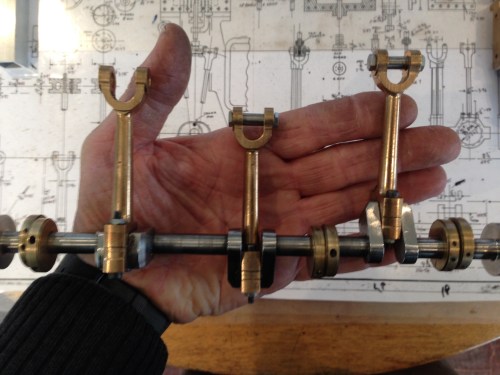
The crankshaft, turned from stainless steel a year or two ago, and the conrods.  The big ends now with lubrication points.

And here are the major engine components, after partial disassembly.

IMG_5170.JPG

At top left is the condensor, then the cylinder block in 2 parts, then the steam supply valve.  The square section tube is going to become the base.  And so on.  You get the picture.  I will count the bits at some stage.

Then I cut and drilled the square section aluminium tube for the base.

IMG_5182.JPG

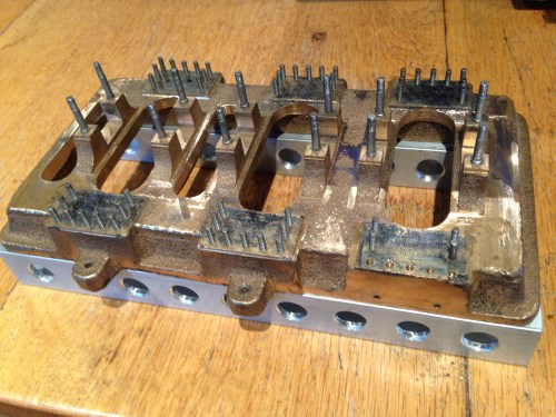
The cast base of the triple, with main bearing studs and column studs in place.  All sitting on the square section alu.  Have not decided whether to bolt it together, or just Loctite it. 

Those holes in the square section were drilled and chamfered on the CNC mill.


The Royal Geelong Show- Vintage Machinery Shed

A few pictures of the Vintage Machinery Shed, at The Royal Geelong Show.   Don’t get me going about the “Royal”. It is a ridiculous anachronism.  But since our head of state is still a Brit (the much admired Queen Elizabeth 2), I suppose we are stuck with the “Royal”.  The engines photographed below are just the ones in the immediate vicinity of the models cage.  I will add some more in a later post.

The boiler used to power the steam engines.

The boiler used to power the steam engines.  wood fired, running at about 35 psi.

The triple expansion marine engine. It powered a tug boat originally. It is steam powered, but only the high and intermediate pressure cylinders are currently powered. The condenser is not fitted to the engine because of the large volume of water it consumes, so the low pressure cylinder is not powered. The rotation of the engine is slightly irregular because only 2 of the cylinders are powered, but it is still a mightily impressive sight.

The triple expansion marine engine. It powered a tug boat originally. It is steam powered, but only the high and intermediate pressure cylinders are currently powered. The condenser is not fitted to the engine because of the large volume of water it consumes, so the low pressure cylinder is not powered. The rotation of the engine is slightly irregular because only 2 of the cylinders are powered, but it is still a mightily impressive sight.  When the engineers learned that I am making a triple expansion model engine, they generously spent considerable time and patience explaining the various components and mechanisms, and involved me with the start up process.  That process is quite complicated, because the engine cannot rotate until the 3 cylinders are heated, and introducing steam heats only the first (high pressure) cylinder.  Separate steam lines heat the other 2 cylinders, and they are closed just before rotation commences.

The crankshaft

The crankshaft, con rods, eccentrics

The low pressure cylinder Stephenson's link

The low pressure cylinder Stephenson’s link

The main steam valve (right), the reversing valve (left front), and the intermediate cylinder start up supply line lever.

The main steam valve (right), the Stephenson’s link reversing valve (left front), and the intermediate cylinder start up supply line lever.

another shot of the valve eccentrics

another shot of the valve eccentrics

This oscillating single cylinder, double acting steam engine with very nice architectural details dates from 1862. It is probably the oldest working engine at the show

This Wedlake and Dendy oscillating single cylinder, double acting steam engine with very nice architectural details dates from 1862. It is probably the oldest working engine at the show.  The governor is not original.

This one is dated 1865.

This Wedlake and Dendy  single cylinder horizontal is dated 1865.  Despite its age, it runs beautifully.

TRIPLE CYLINDER HEAD CAPS

IMG_2566

The head caps sitting in position.

Turning these fairly simple pieces should have been a doddle. Trouble was that they are relatively thin and soft and holding them in a three jaw chuck on the lathe was OK, until the rather sharp tool got pulled into the work. The cutter jammed, the workpiece was pulled out of the chuck and thrown across my workshop, with a a lot of superficial damage to the workpiece.
Fortunately, there was enough material remaining to machine out the dents and cuts. Also, it forced me to make a jig to hold the workpiece securely. Since the head caps are all different sizes, I had to change the jig dimensions after each head was machined, which was time consuming, but the method worked well with no further hitches.  Also, I changed from a tangential, sharp, high speed steel cutter, to a neutral rake carbide (and therefore less sharp) one, and no further dig ins were experienced.

IMG_2568

The jig for turning the reverse side of the cylinder heads, and the underside of the low pressure head (the biggest one)


Next I will drill and taps the holes for the small bolts which secure the head caps.  All 56 of them.  I sense some more CNCing in my near future.

TRIPLE CYLINDER BLOCKS JOINED

The heavy chunks of brass which form the cylinders, and the intermediate cylinder valve chest, have been machined externally, and bolted together.

IMG_2553

The low and intermediate pressure block on the left, the IP valve chest (with the round boss), and the high pressure cylinder block on the right. All bolted together. Almost ready for cylinder boring.

The IP valve case cavity has been machined, but 3mm too wide. I think that this error will not matter, but if it does I will silver solder some extra material to get to the specified dimension.  (the external  dimension of the steam chest is deliberately left too big at this stage.  It will be blended with the cylinder blocks later.)

Now that these pieces are together, I can do the cylinder boring and complete the external dimensioning and finishing.

GSMEE EXHIBITION 2

Wimshurst Electrostatic Generator, made by Peter Bodman.  Creates sparks up to 100mm long, which drill minute holes in interposed paper sheets.  No-one volunteered to ry it with a hand.

Wimshurst Electrostatic Generator, made by Peter Bodman. Creates sparks up to 100mm long, which drill minute holes in interposed paper sheets. No-one volunteered to try it with their own hand.

IMG_2238

Vacuum engine made by Peter Bodman.

IMG_2263

Awesome model of pre-dreadnaught ship circa 1902 “Preussen” made by Walter. It is approx 1 meter long, weighs 16kg, and is radio controlled. The 28cm gun turrets are also radio controlled, but do not (as far as I know) actually fire.  To the right is a model of Columbus’s “Santa Maria”.

IMG_2264

The detail in the model has to be seen to be believed.  Every plank of the decking is individually made and fitted.

IMG_2284

Walter showed us the inside construction, engines, and electronics. The model was made from a few old photographs, and simple side and top elevations.

IMG_2285

Hull with the superstructure removed

IMG_2241

A very old pressure gauge, restored so that the workings are displayed, to reveal how it works. By Stuart.

IMG_2259

This model boat was made by 8 year old Niall, with some supervision from his Dad, William. The gun is actually a radio controlled water cannon which fires up to 3 meters, to the wet surprise of some spectators. Niall and William both had a fantastic experience with this project.

IMG_2262

William with some of the wonderful boat and ship models which he (and Niall) have made in recent years.

IMG_2249

A model working ship steam engine and boiler, by Walter. Twin cylinder, double acting cylinders. This should be jewellery, worn around the neck of a beautiful woman.  OK, that is a little over the top, but you get the idea


IMG_2250

Close up of the marine engine by Walter

IMG_2277

Les Madden with his partly completed Atkinson Differential Engine Model, originally patented in 1887. The wooden model on the left was built by Les in attempt to figure out how it worked! He made the wooden parts to have aluminium castings made.

IMG_2278

Les Madden’s Differential engine.

18 radial cylinder aero engine, by John Ramm.  The hand carved propeller is approx 600mm long.

18 radial cylinder aero engine, by John Ramm. The hand carved propeller is approx 600mm long.

IMG_2253

Detail of the aero engine. John showed 3 aero engines. He is currently making a 12 cylinder Spitfire Merlin engine which he will have finished by the time of the 2015 exhibition.

IMG_2281

Stuart Tankard’s prize winning hit and miss engine, was running throughout the exhibition. 17.7cc, 4 stroke, 4:1 compression, running on gas.

IMG_2282

Close up detail of the hit and miss engine. A standard the rest of us can aim for.

IMG_2283

A vertical boiler made by Stuart Tankard

Thomas Lord in the cabin of his steam truck, giving some driving tips to Niall

Thomas Lord in the cabin of his steam truck, giving some driving tips to Niall

These photos are just a small fraction of the many model engines, ships, trains, tools and other projects created and displayed by members and friends of GSMEE.

GEELONG SOCIETY OF MODEL AND EXPERIMENTAL ENGINEERS ANNUAL EXHIBITION 1

Steam truck, built by Thomas Lord.  See following videos

Steam truck, built by Thomas Lord. See following videos

The GSMEE held its annual exhibition of projects by members and friends, on the weekend of 15-16 November 2014, at Osborne House, Swinburne Ave, Geelong North.
I will post some pictures and videos of some of the superb model engines, boats, ships, tools, aero engines, and even a full size road legal registered steam truck, pictured above. Due to the size of the files and the crap Internet connection available here, I will spread the post over several days.

To continue with the incredible steam truck, made over the past decade by Tom Lord, see the following videos.  (sorry, no luck with the upload. I will try again tomorrow)


TAPPING HOLES. BOLTON 9. (Triple Expansion Marine Steam Engine)

Today I drilled and tapped the holes for the bolts which secure the crankshaft main bearings.  I had accurately marked the bearing mounts  in the previous session (see previous photos), and calculated and recorded the DRO (digital read out) position for each hole.  So going back to that position for each step in the process was easy and quick.  The steps today were centre drilling, drilling the 3.3mm holes, and tapping the 4mm threads to a depth of 20mm.

Centre drilling is done with a centre drill bit in an accurate chuck in the milling machine.  Centre drill bits are inflexible and will not wander over the work like an ordinary twist drill bit,  The centre drilled hole is deep enough to create a chamfered edge to the hole.  All 12 holes are drilled with the centre bit, then all 12 drilled with the 3.3 mm bit, then all 12 are threaded.  The DRO positions the work within 0.005mm each time, and the repositioning is very fast, much faster than going to a position doing all 3 processes, changing the bit for each one, then moving to the next position.

The threading was done with a Tapmatic 30 tapping head in my milling machine.  See photo.  This takes about 10 minutes to set up, but the tapping process for the 12 holes then took about 5 minutes.  I use Rapid Tap lubricant for tapping, even in brass.  I guess that manually tapping the holes would have taken about the same time, but it was so satisfying to see the Tapmatic do its stuff.  I use the Tapmatic for any tapping job involving more than about 8-10 holes.  Fewer than that it is quicker to do them manually.  The Tapmatic has a adjustable clutch.  I have never broken a tap in the job using this machine.

Incidentally, I have decided to use nuts and bolts and screws and studs in preference to metric cap screws for this model.  The appearance wins out over practical expediency.  So why the metric threads for this job today?  The specified thread was 5/32″ which is 3.96mm, so I decided to go with the 4mm metric, for which I have the tools already.


Tapping the main bearing blocks using the Tapmatic and Tap Magic.

Tapping the main bearing blocks using the Tapmatic and Rapid Tap.

Burrell Traction Engine

Castings for Burrell steam traction engine.

Castings for Burrell steam traction engine.

IMG_1958 IMG_1959 IMG_1960 IMG_1961 IMG_1962

Bolton 9 Triple Expansion Steam Engine

My next steam engine project will be to make from iron and gunmetal castings and bar stock, a steam engine which will have similarities to the engines of the Titanic.  It will have 3 cylinders, increasing in size, so that steam passes from the smallest to the intermediate to the biggest, thus being used 3 times before being exhausted.  It will be much more complex than the other engines pictured to date on the blog.  My other engines have taken about a year each to build, so I predict that this one will take a similar time.  We will see.  There will be no rush.  My aim is to enjoy the build and end up with a working engine.  It might even end up in a boat.

I have the plans, and the castings are on order.  The supplier (Kelly Mayberry at E&J Winter, Sydney) had to order new castings, so they are currently being cast and collected.  My next post will be when the castings arrive.  If you are interested, go to the E&J Winter web site and browse the catalogue.  I am not exactly sure about the final cost of the castings but it will be approx $A1500.  Not cheap, but SWMBO says that it keeps me off the streets, and is probably less than belonging to a golf club.