johnsmachines

machines which I have made, am making, or intend to make, and some other stuff. If you find this site interesting, please leave a comment. I read every comment and respond to most. n.b. There is a list of my first 800 posts in my post of 17 June 2021, titled "800 Posts"

Tag: Pressure gauge

London Museum of Science Revisited

I am back in oz as of a few hours ago.  Freezing and wet.  Was 26c in London today.

On my last afternoon in London I had a few hours spare.  So I caught the tube to have a final farewell to the Trevithick dredger engine and to reshoot some photos which I had messed up at my visit 3 weeks earlier.

P1032708.JPG

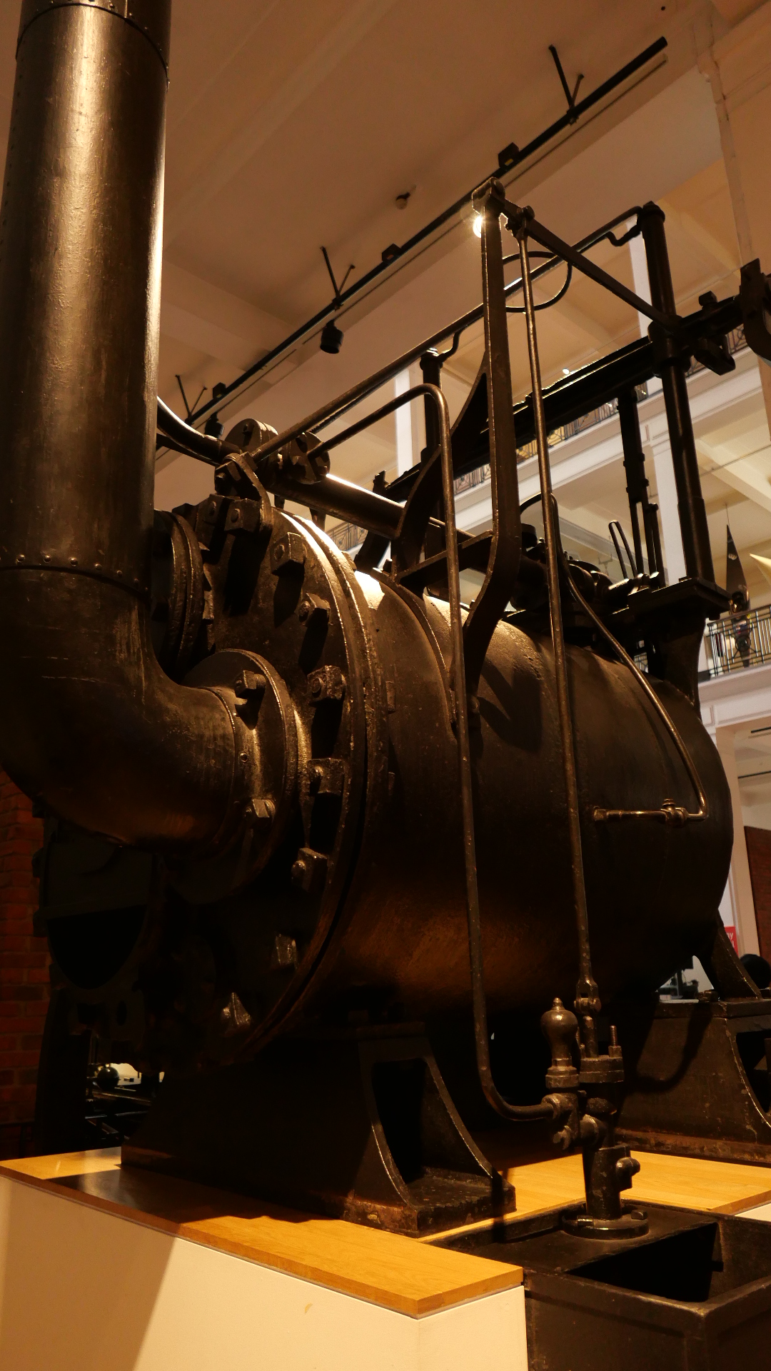
Trevithick dredger engine in the LSM.

…and I spent a very pleasant hour photographing the engines in the Energy Hall again.

And on wandering further into the building I discovered that on the previous visit I had totally missed about 2/3 of the entire museum, including the model of the Trevithick road vehicle which had been made as a concept model by Trevithick’s brother in law, a clock maker.

Unfortunately it was bottom lit and behind glass, so very difficult to get good photos.

P1032563.JPG

From above

P1032569.JPG

From the side.

P1032571.JPG

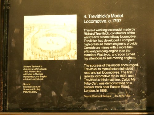
The model is more akin to his road vehicle “Puffing Devil” than the rail locomotive.

P1032576

Quite modern looking lathe by Richard Roberts 1807.  With lead screw and outboard gears for threading.

P1032500.JPG

Beam engine designed by James Watt 1797.


P1032605.JPG

Model of a steam powered workshop, with many tiny exquisitely modelled lathes, shapers, presses, saws, and a steam engine.  Those lathes are about 3″ long.

P1032508.JPG

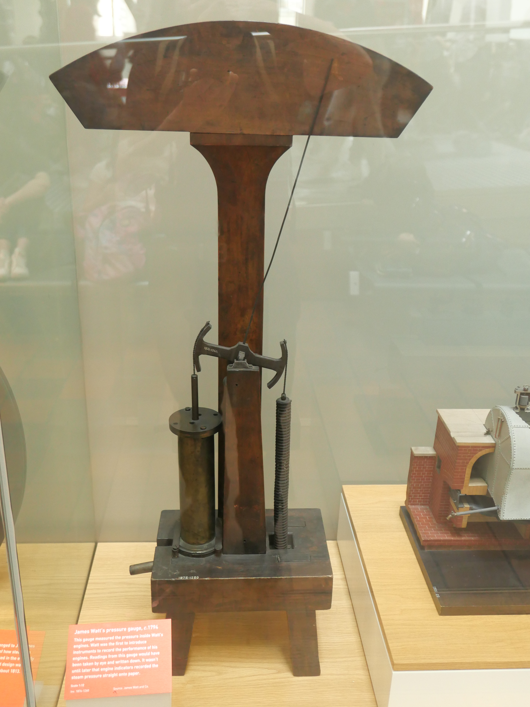
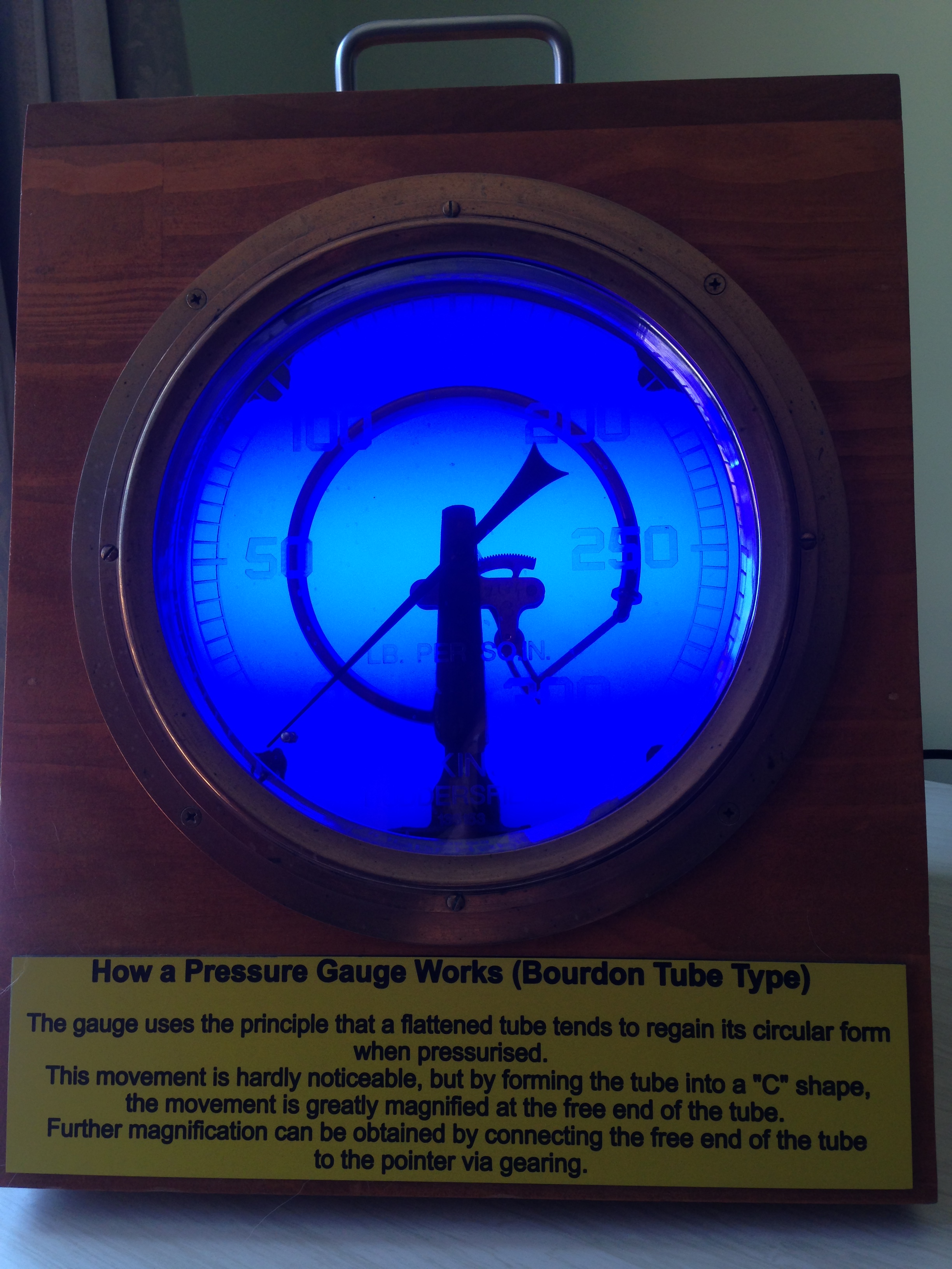
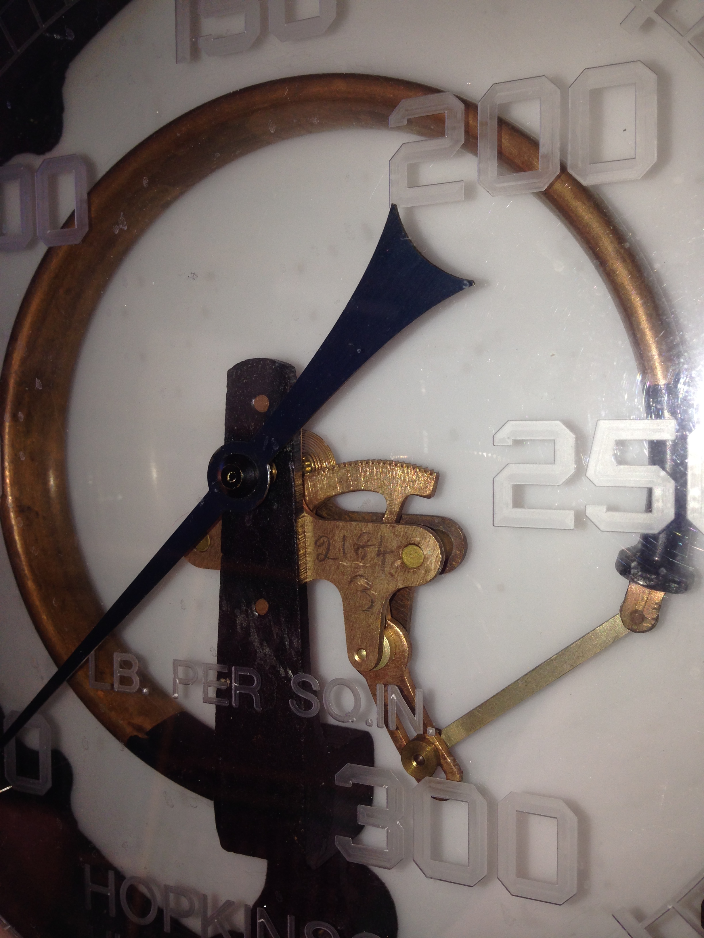
And a 1:12 model of a pressure gauge of James Watt, 1794.  60 years before the invention of the Bourdon tube.

P1032664.JPG

And this one amused me.  It is a 1987 Colchester CNC lathe, with Fanuc controller.  It is 2 years newer than my Boxford CNC lathe.

This really was the finale of my adventures in the UK.


Another pressure gauge.

Stuart Tankard rescued this large pressure gauge from being scrapped, and restored it.  It is now often on display at our club exhibitions.  I confess that I did not pay it much attention, until my recent interest in boilers and pressures.

IMG_6781.JPG

It is a big gauge, and the works are all on view.  The blue light is aesthetic I think.

IMG_6780.JPG

You can see the Bourdon tube, the link, the quadrant.  The nice aspect is that this gauge is very accurate.


Boiler. The Pressure Gauge.

I have learned a bit about pressure gauges from Frank, who used to manufacture them, and from Stuart, who made a 5″ vertical boiler which was the inspiration for my 6″ build.

For one thing, pressure gauges become less accurate as they become hotter, so steam should not be allowed into the Bourdon tube.  Which means that there should be water in the line between the steam and the gauge.  That can be managed with a pig’s tail coil of copper tube, or a water reservoir, which is what I made.

For another thing, gauges have varying accuracy, and I am fortunate in having a friend who has calibration equipment, so I can obtain information about the degree of accuracy of my selection of British and Chinese gauges.

Then there is the aesthetic appearance of the gauges.  A matter of taste, but I really like the older “Smiths” made in UK gauge.

So this is what I ended up installing.  I might change my mind later, but for the moment…..

IMG_6765.JPG

These are the gauge components.  The Smiths gauge itself (needs a 100 psi red line), the brass support made today, and the copper tube which provides the water barrier.

IMG_6766.JPG

I like it!  Hope that you agree.  Still need that shed tidy-up.

IMG_6767.JPG


Adjusting Pressure Gauges

In a recent post about 2 pressure gauges which I bought at a club auction, a reader (Daredesign) asked whether pressure gauges are able to be adjusted if the calibration is out.


One of our GSMEE members used to manufacture pressure gauges, so I asked him.

Frank and an artist made about one gauge per day.  They were precision instruments, reading within 1:200 of the gauge reading.  And priced accordingly.  The face marks were painted by hand onto each gauge face by the artist, in positions marked by the instrument maker in a temperature controlled room.

Pressure gauges CAN be adjusted.  And the better the quality of the instrument, the more readily it can be adjusted.  The means of adjustment depends on the nature of the error.

If the error is a constant number throughout the pressure range, the pointer is removed from its tapered spindle and replaced in the new position.

If the error varies throughout the pressure range, the adjustment is of the inside mechanism.  Two arms named the link and the quadrant are joined together and the join position and angle between the parts can be adjusted.  The length of the link can also be adjusted.  Frank gave me a detailed explanation of the types of errors and the adjustments, and I do not remember the details.  I imagine that these procedures should be left to experts like Frank.

Frank also explained the workings of the Bourdon tube which is the main component of most pressure gauges.  The Bourdon tube is a thin walled, oval section, copper-beryllium  alloy tube, bent into an arc, and closed at one end.  With pressure increase the tube tends to straighten, and the movement is translated into movement of the dial needle.  The copper alloy is chosen because of a property called hysteresis, which I understand means that it returns exactly to its original shape when the pressure in the tube returns to its resting level.Bourdon tube pressure gauge. 

In this diagram, the quadrant is named “sector”.  The angle between the segment lever (or “quadrant”) and adjustable link should be 90 degrees when the pressure is halfway in its range.

So, I hope, Daredesign that this answers your question, and that I am reproducing the information accurately.


6″ Vertical Boiler. Calibrating the pressure gauge

I bought 2 pressure gauges at a recent Model Engineering Club auction night.  I paid $AUD40 for the pair, although I was really only interested in the smaller one.

It was a bit of a gamble.  Would they work?  Accurate?

Stuart mentioned that he had an instrument for calibrating gauges, and he checked my gauges.

IMG_6624.JPG

This gauge was item 51 at the auction.  It is about 4″ diameter and has some style!   Brass of course.   The cream painted instrument with the shiny brass weights is the calibration gauge.  It confirmed that my gauge was spot on at pressures of 50, 100, 150, 200 qnd 250psi.

The smaller gauge, 38mm  1.5″ diameter which I will use on the Trevithick dredger engine, was not quite as accurate, being 2.5psi out, but is adequate for use.  It is also British made, brass, and nice appearance.

IMG_6625

IMG_6625

IMG_6625