Byrnes Inspired Table Saw. – 5
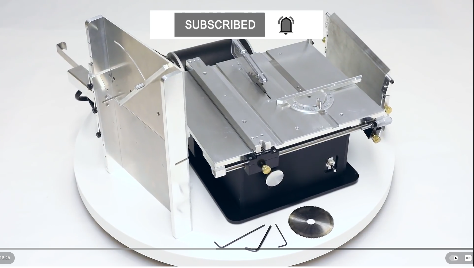
When I designed my “Byrnes” saw for model ship building, I made some changes. Improvements I thought. Although Jim Byrnes was an engineer, and I clearly am not. I am an amateur who likes to have a go.
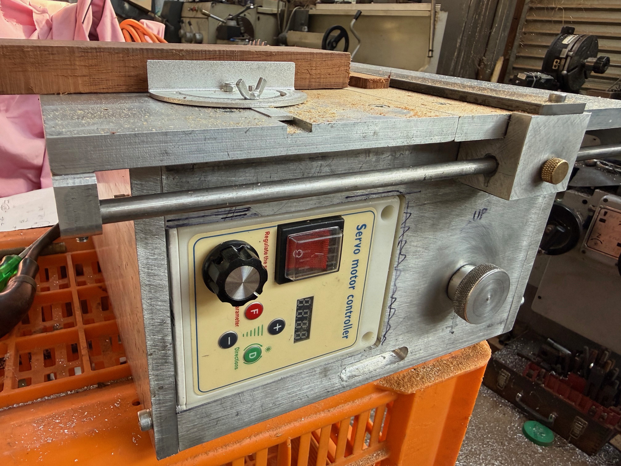
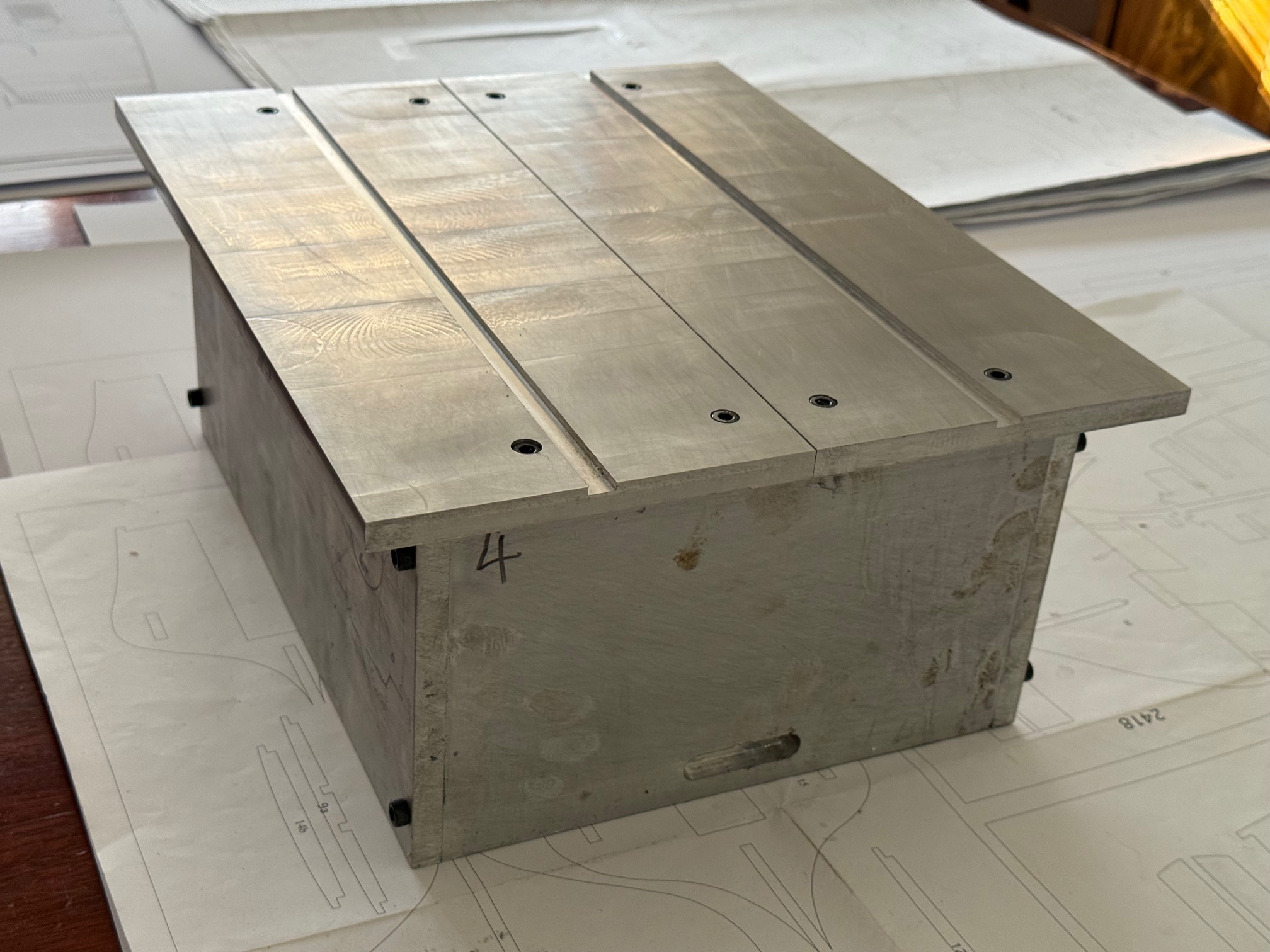
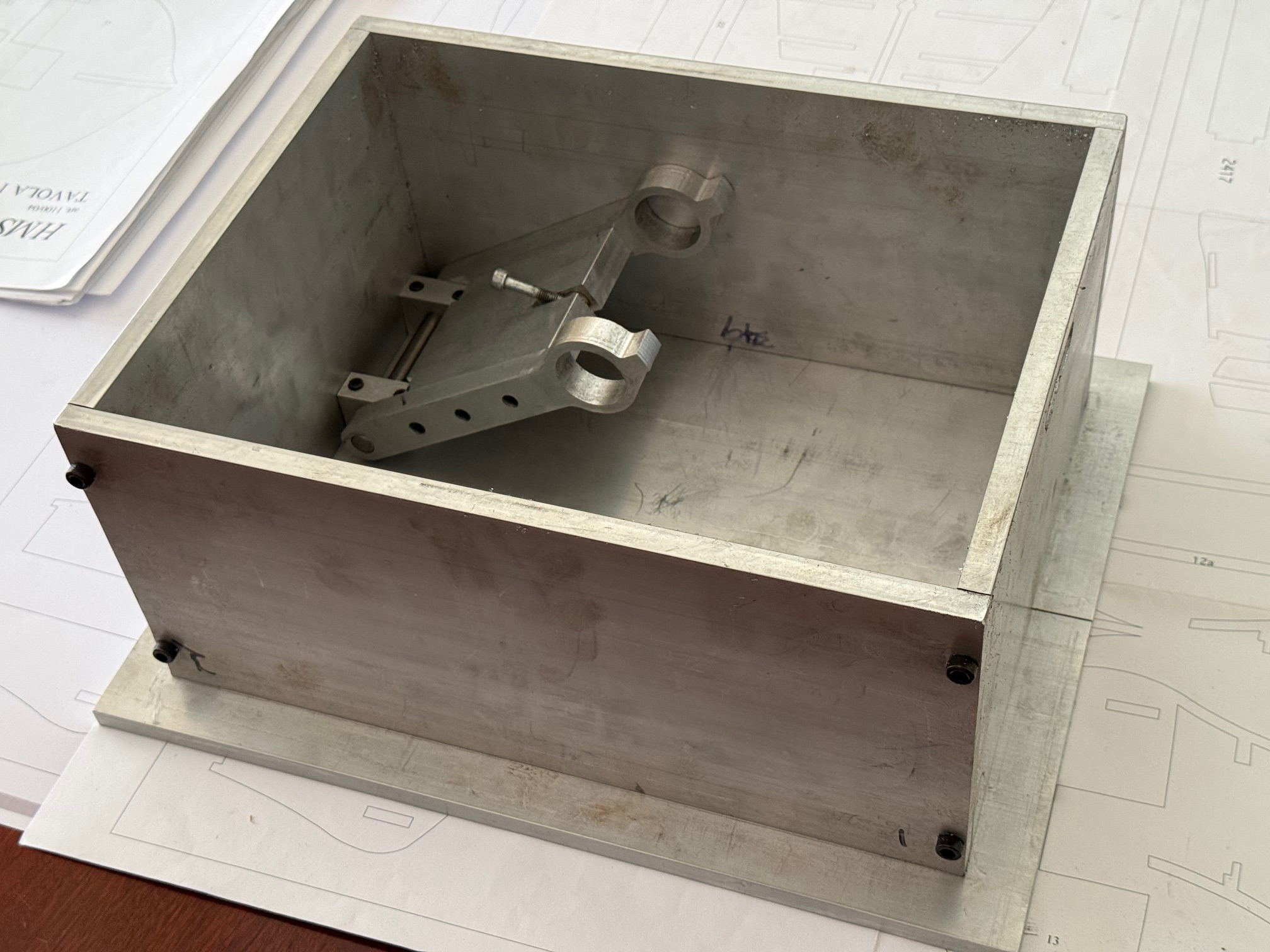
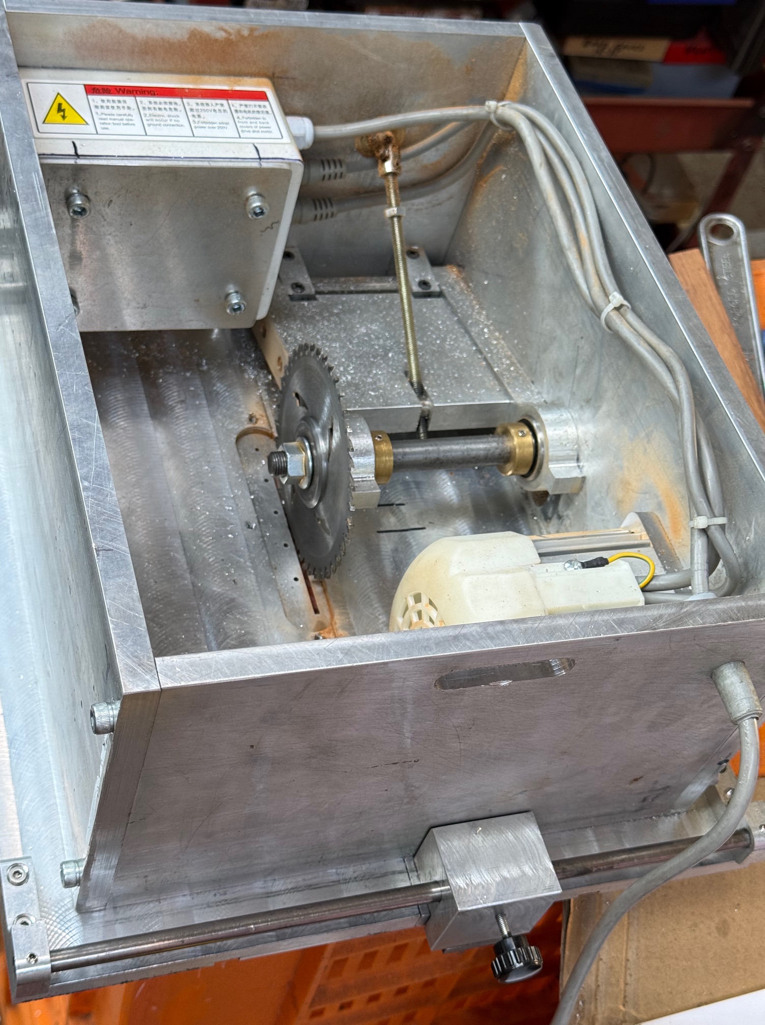
One change was to use an AC Servo 1hp motor rather than the old style 200watt external mounted one on the real Byrnes tools. It meant that I could mount the motor and the control box inside the base of the saw. Like this…
But, one problem with this “improvement” was that in the original, the motor was hinged, although external, and the weight of the motor maintained tension on the drive belt.
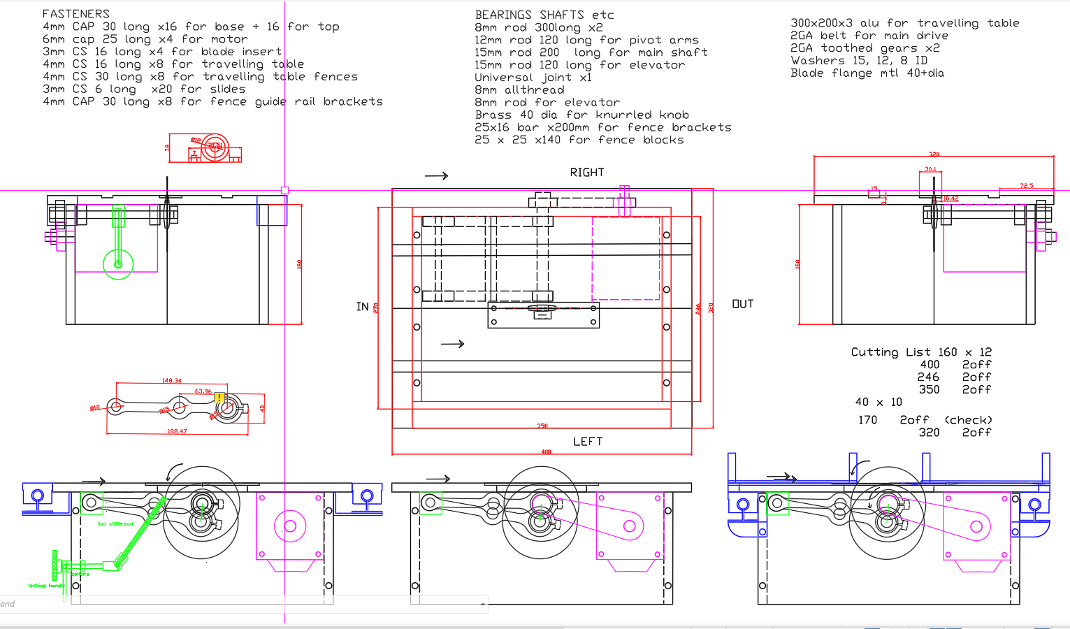
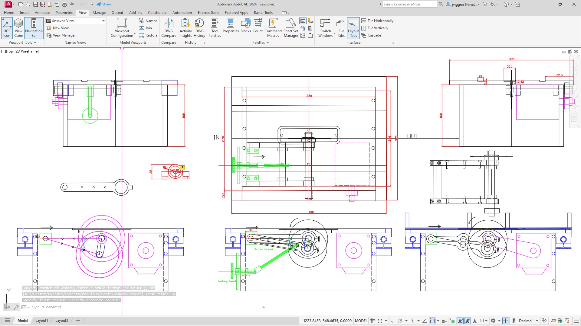
In my design the internal motor is fixed in position, although the cradle which holds the saw blade is hinged, so the distance between the motor and the saw blade spindle changes with height adjustments of the blade. Which means that the belt needs an extra tensioning mechanism.
I have been pondering that mechanism, and leaving it until everything else was bolted in position. Today was the day that I tackled the solution.
I decided that a spring loaded mechanism was the best solution to the belt tightness situation, although I had no idea what sort of spring, its size and stiffness etc would be required. So I dived into my “springs” drawer, where I toss all springs which I come across.
Then I set up a sort of experiment.
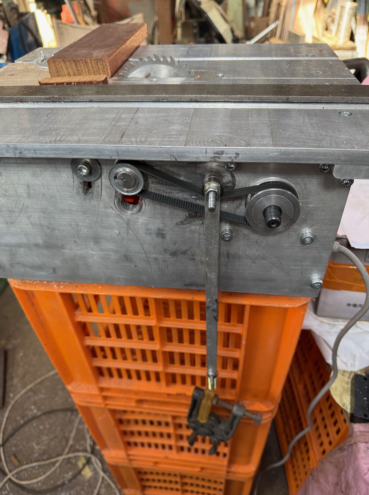
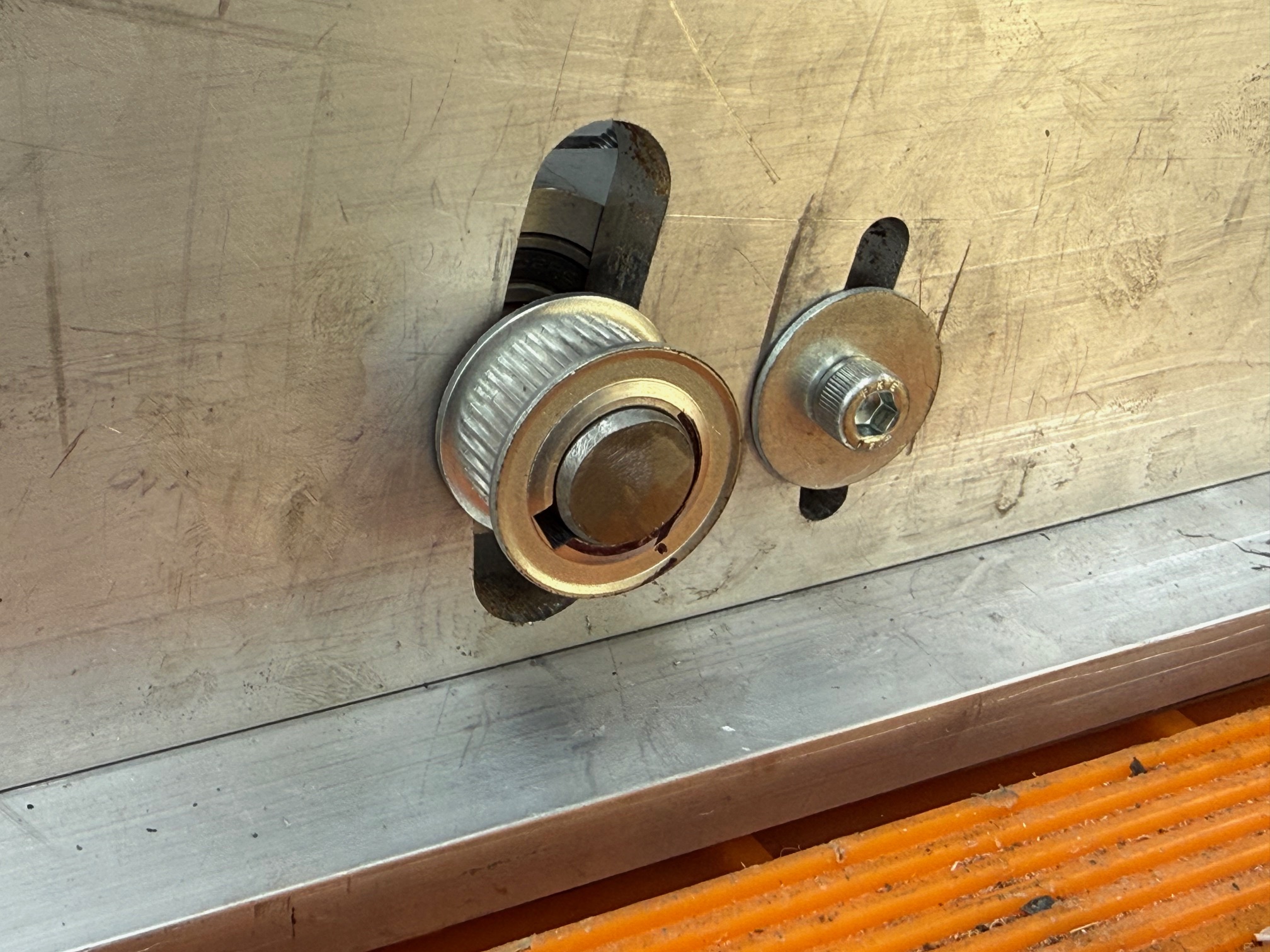
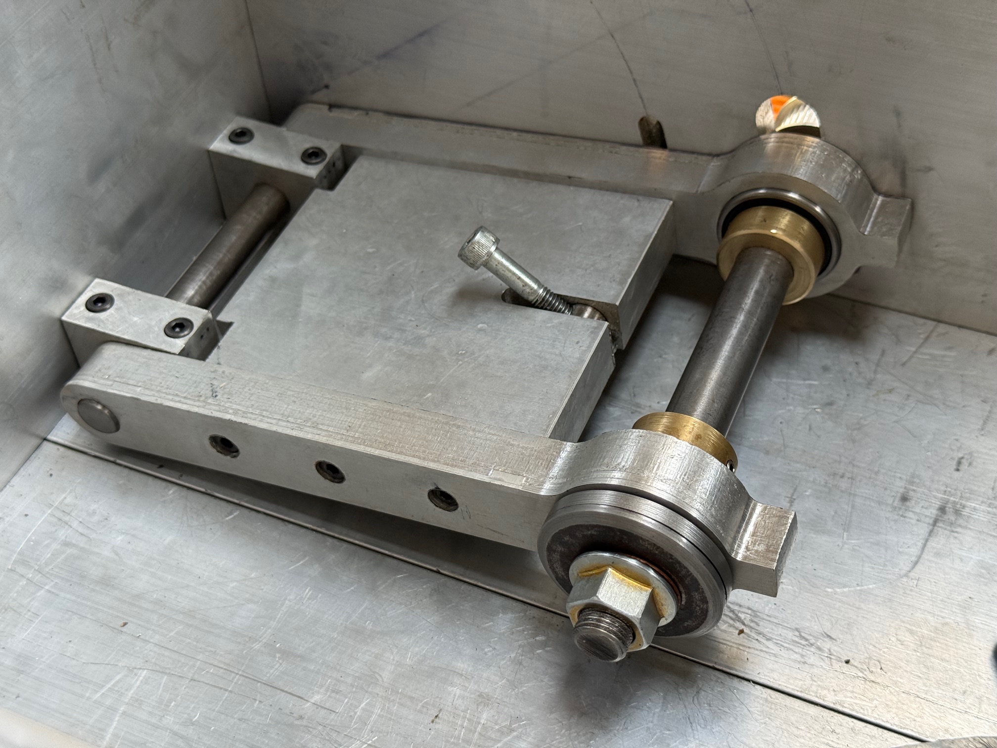
The belt has 2x 6mm wide ball bearings on a 6mm shaft, hanging off it. The 1.5mm thick alu bars have a weight suspended (a clamp). Later, I increased the weight to 2 clamps.
Then I ran the saw, even cutting some Jarrah bits of wood (the first use of the saw in “anger”). All the while watching the belt and its weights to determine which weight gave the smoothest and best results. Extension of the spring from 25mm to 50mm gave the best results, so that is the length that I will install the spring under tension. I tried the cutting at different saw elevations to confirm the initial results. A bit rough and ready, but better than total guessing.
And here are the results of cross cutting and ripping the jarrah…
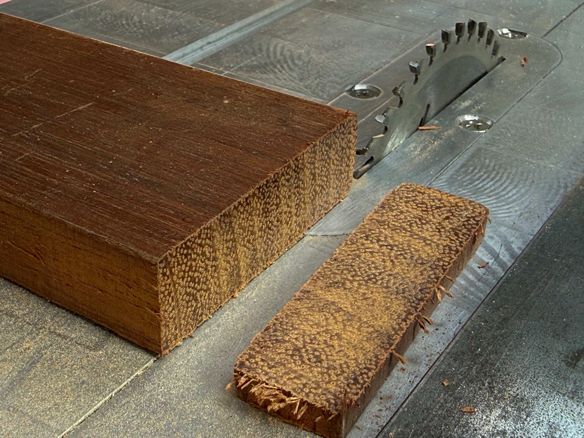
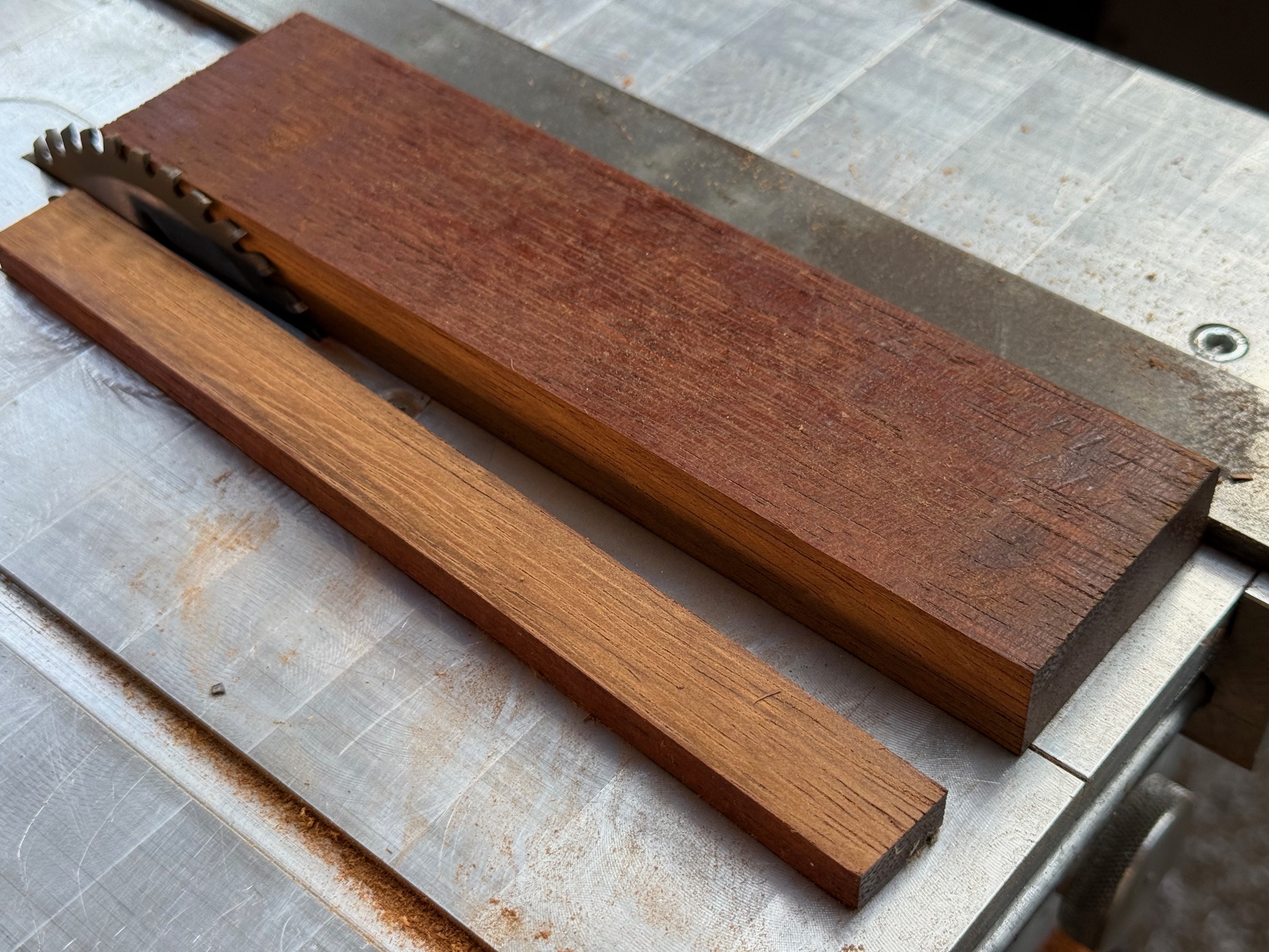
And at lower saw blade heights the saw worked even easier. So my belt tensioner will be cut to size and installed permanently. Oh, and I will make a 0.25-0.5 dome to attach to the rim of the 2 17x6x6mm bearings, to keep the belt positioned centrally on the bearings. Will probably glue it to the rim. Watch for some photos in a day or so.
The slot in the blade insert of the saw bench top was cut by the blade in the photos. I will make some more inserts, one for each blade kerf, to minimise the tearing of the wood being cut. That is why I chose aluminium for the inserts. Although I might make some from clear acrylic so I can see what is happening below.
I will also make a cover for the belt and gears, and a handle for the height lock. Then a protractor fence for angle cuts, and an extension to increase the height of the parallel fence.
And I hope that you noted in the first photo how neatly I have bundled the wiring away from the cutty bits.
Getting close to being finished!