johnsmachines

machines which I have made, am making, or intend to make, and some other stuff. If you find this site interesting, please leave a comment. I read every comment and respond to most. n.b. There is a list of my first 800 posts in my post of 17 June 2021, titled "800 Posts"

Tag: stationary engine

First taste of steam for the MODEL TRIPLE EXPANSION ENGINE

I made a video of this first run, but I am experiencing great frustration uploading it, due to our totally pathetic Internet speeds here in Australia.  I will include it later in this post, but the resolution is way down.  I will upload a higher res version next weekend.

1 setup.JPG

Stuart Tankard’s superb gas fired vertical boiler, was also getting its first run powering a steam engine.

2 setup.JPG

We did not connect the condenser until later.

OK, so here is the video.  Again, apologies for the low res quality.

Steam Engine Oilers

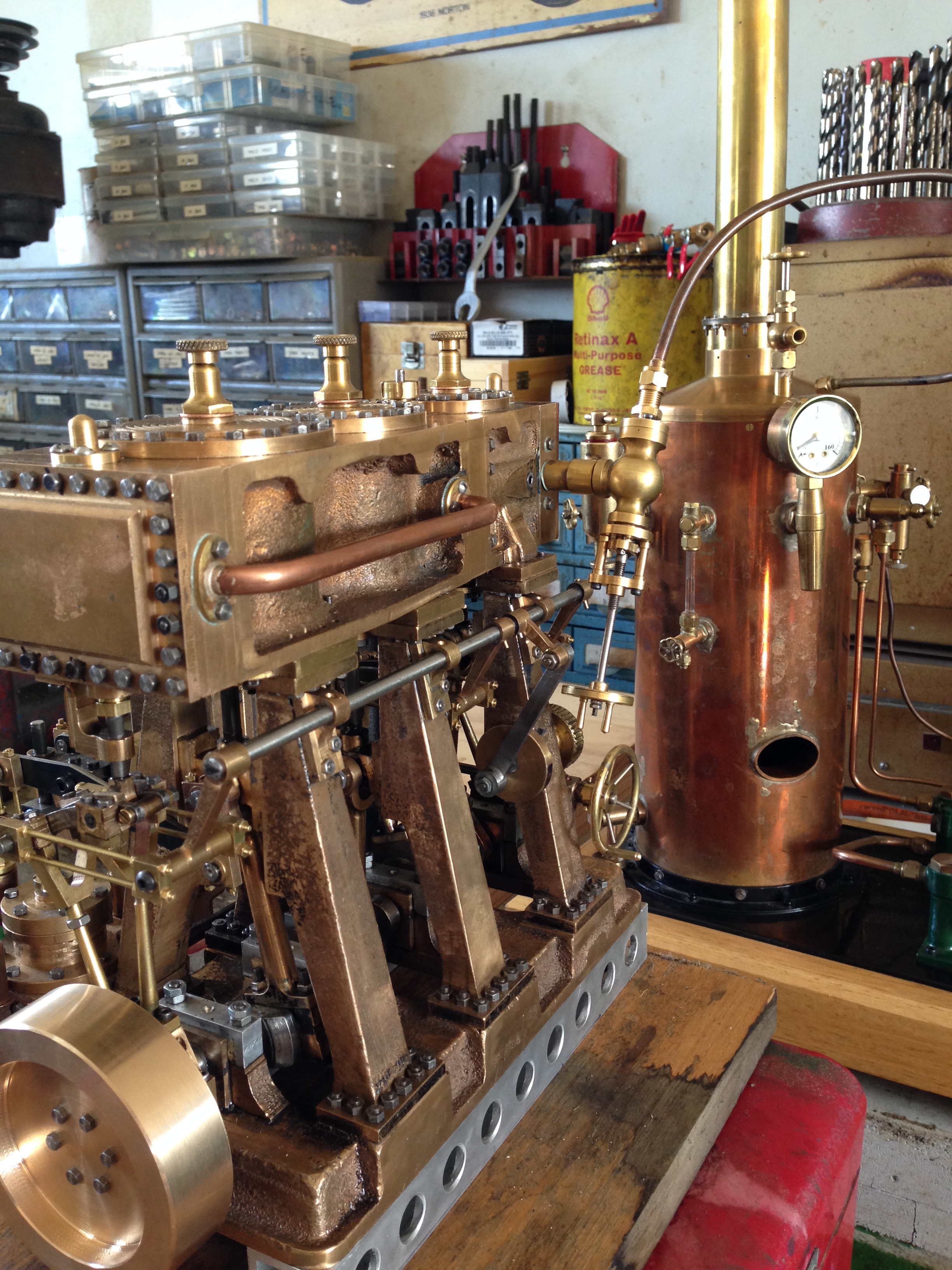
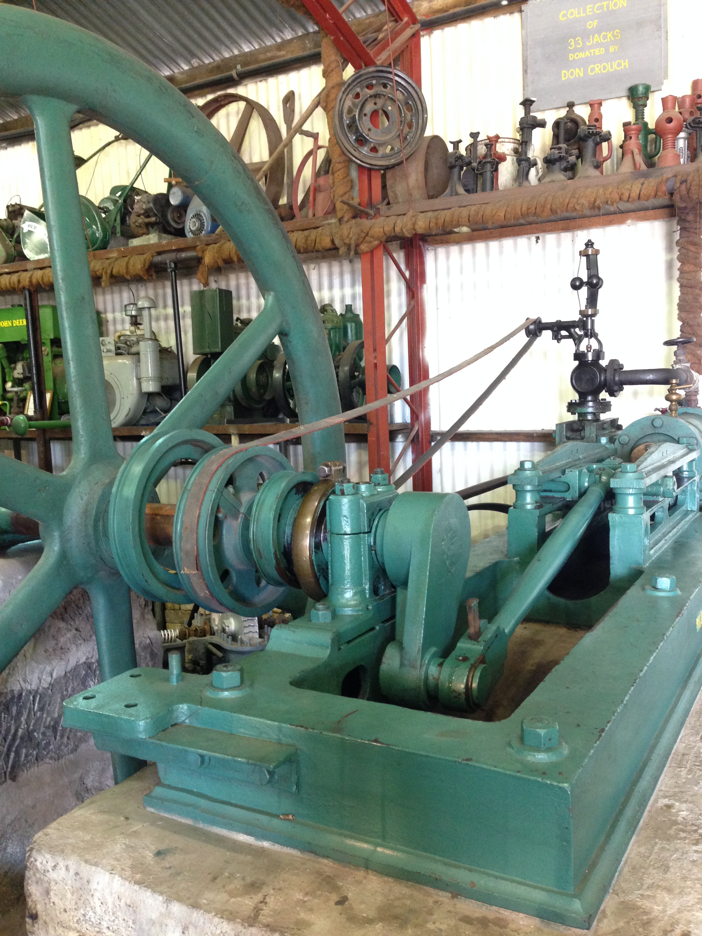
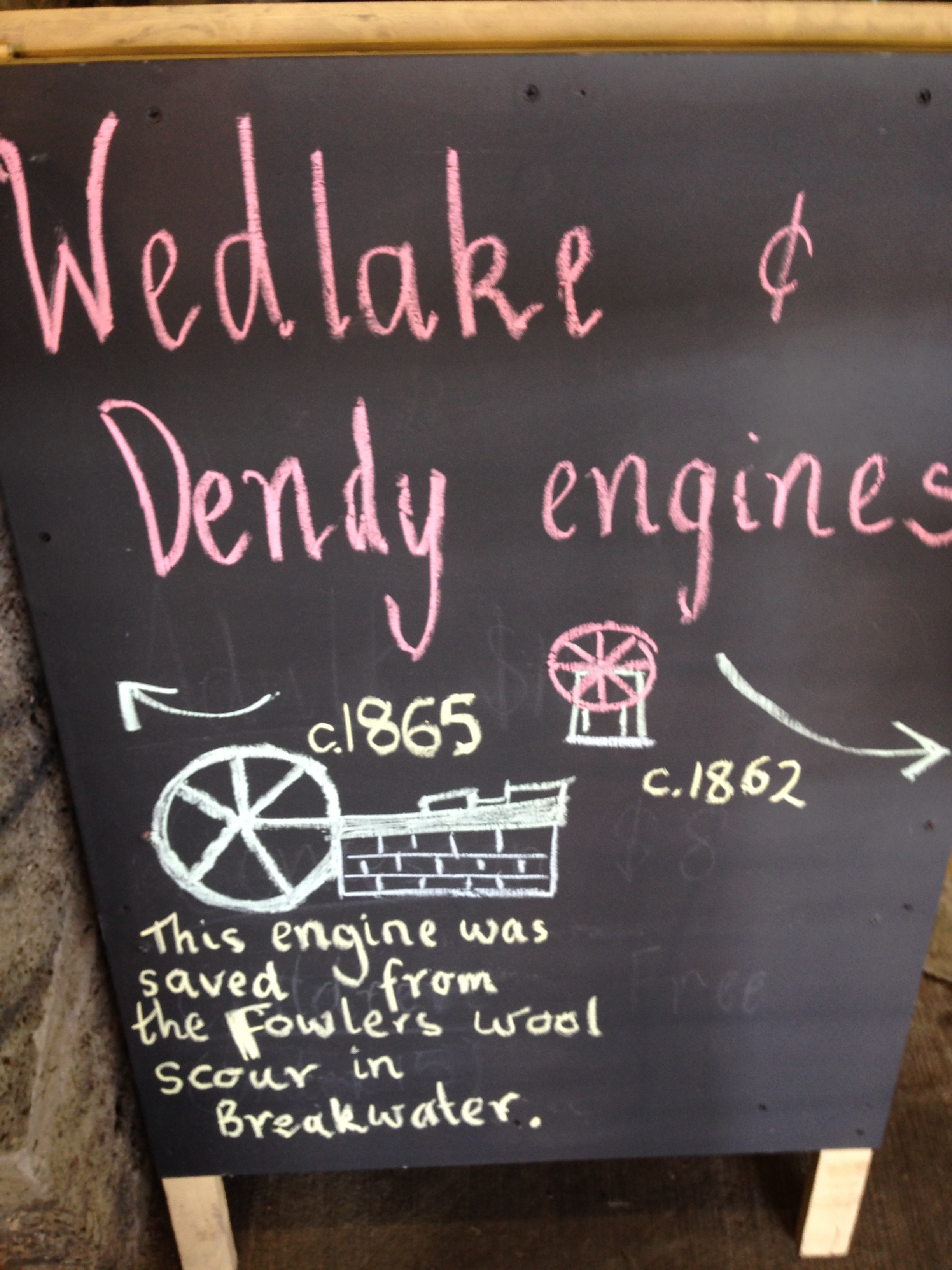
Knowing that I have an interest in CNC machining, Tom, from the Vintage Machinery Club in Geelong asked me to make a pair of oilers for a very old Wedlake and Dendy steam engine.  The engine is a large (to me anyway) stationary engine, which is run on steam several times each year.  The oilers for the cross slides were missing.

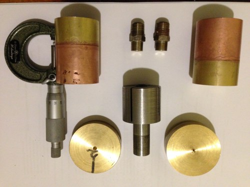
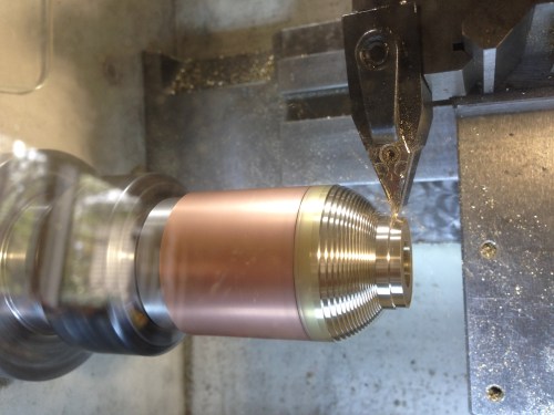
We searched the Internet for pictures of W&D steam engines, but could find no pictures or diagrams of the oilers.  So Tom sketched a design, and I drew a CAD diagram.  The dimensions were finally determined by the materials which I had available…  some 1.5″ brass rod and some 1.5″ copper tube.

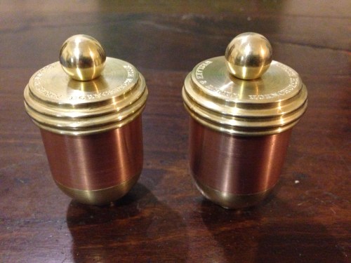
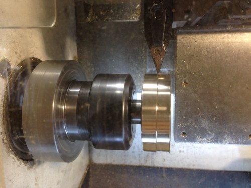
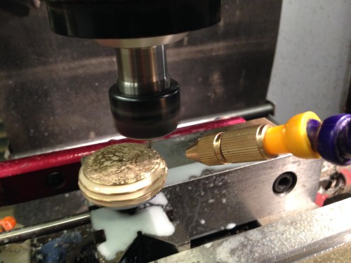
This is the almost finished product.

IMG_4250.JPG

Just needs 1/4″ BSPT fittings and and oil wick tube so they can be fitted to the engine.

IMG_4222.JPG

The copper tube silver soldered to the brass cylinders (top), the brass blanks for the lids (bottom) and the mandrel to hold the assembly (bottom centre) during CNC turning and drilling.

IMG_4246.JPG

The mandrel to hold the body (left) and the mandrel for the lid (right).  The cap screw head and hole in the mandrel have a 2 degree taper.  The slits were cut with a 1mm thick friction blade.

IMG_4243.JPG

Rough turning the base.

IMG_4231.JPG

Turning the lid.  The mandrel is held in an ER32 collet chuck

IMG_4245.JPG

Engraving the lid.  Using a mister for cooling and lubrication.  16000rpm, 200mm/min, 90 degree TC engraving cutter.

IMG_4251.JPG

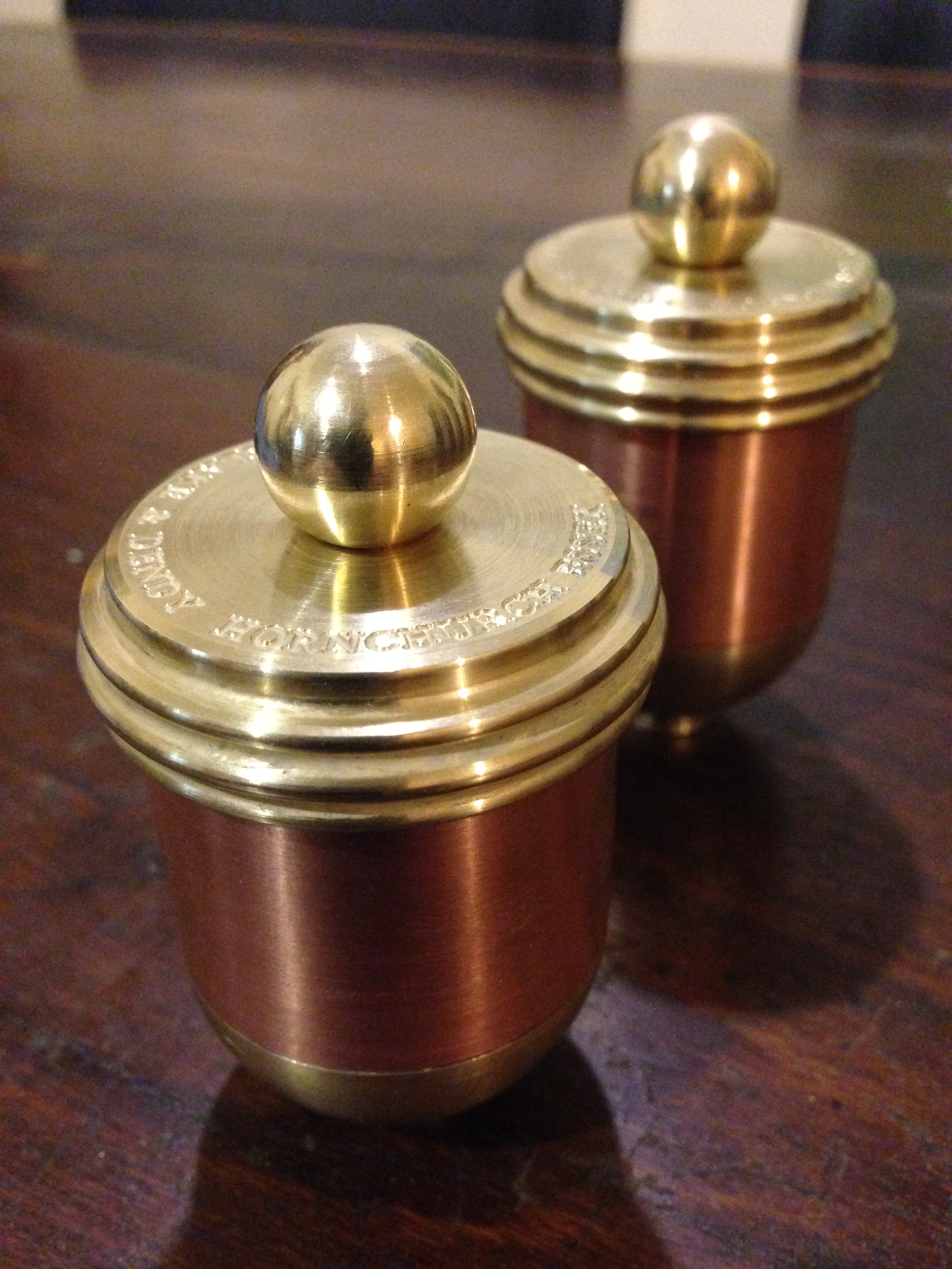
The oilers work by wicking the oil from the reservoir into a tube which drains through the base onto the engine slide.  When the wick tubes are fitted the oilers can be fitted to the engine.

IMG_3196.JPG

The 1865 Wedlake and Dendy

IMG_3195.JPG

1865

My lathe is a Boxford TCL125, using Mach3.  The G code is generated using Ezilathe.

Below is a link to an oil cup from “USS Monitor”, of American civil war fame.   One of the first ironclads, powered only by steam.

http://www.marinersmuseum.org/blog/2010/04/one-oil-cup-down/

(ps. The  lathe which I was converting to CNC was the subject of previous posts and is now working, but needs some guards fitted and a bit of fine tuning.)

GEELONG SOCIETY OF MODEL AND EXPERIMENTAL ENGINEERS ANNUAL EXHIBITION 1

Steam truck, built by Thomas Lord.  See following videos

Steam truck, built by Thomas Lord. See following videos

The GSMEE held its annual exhibition of projects by members and friends, on the weekend of 15-16 November 2014, at Osborne House, Swinburne Ave, Geelong North.
I will post some pictures and videos of some of the superb model engines, boats, ships, tools, aero engines, and even a full size road legal registered steam truck, pictured above. Due to the size of the files and the crap Internet connection available here, I will spread the post over several days.

To continue with the incredible steam truck, made over the past decade by Tom Lord, see the following videos.  (sorry, no luck with the upload. I will try again tomorrow)


Beam Engine Driving Wheel 2

The aluminium disk was drilled then reamed to 19.05mm (3/4")

The aluminium disk was drilled then reamed to 19.05mm (3/4″)

IMG_2207

Then a shaft was pressed into the disk. The shaft is the same as the shaft on the beam engine, in fact it is from the same stock. It was centre drilled at the ends in preparation for turning between centres, and shaping the driving wheel.   This should result in a wheel which runs true and does not wobble when installed onto the beam engine. 

TRIPLE EXPANSION MARINE ENGINE 2

Reducing the width of the aluminium plate to 140mm, so it will fit into my milling vice

Reducing the width of the aluminium plate to 140mm, so it will fit into my milling vice.  The plate is clamped to an angle plate.

Squaring the ends.

Squaring the ends.

IMG_2153

The base plate bolted to the aluminium plate. Care was taken to fix the brass base centrally and parallel to the aluminium. The fixing bolts are 3mm cap screws, and the holes through the brass plate are 3mm, so even if the brass base is removed, it will go back on in exactly the same position.

IMG_2154

I finished the day by making a spur gear for my brother’s lathe.


The gear attached to the shaft using Loctite.  If the Loctite is inadequate, the gear can be pinned to the shaft.   In the post tomorrow, to Townsville QLD.

The gear attached to the shaft using Loctite. If the Loctite is inadequate, the gear can be pinned to the shaft. In the post tomorrow, to Townsville QLD.  The photo shows why metalworking is an unsuitable hobby for a gynaecologist.

TRIPLE EXPANSION STEAM ENGINE 1

The base casting.

The base casting.

The base of the base, machined flat

The base of the base, machined flat

The base, with 6 pillar mounting areas machined parallel & coplanar, and the crankshaft mounting blocks after an initial skimming.

The base, with 6 pillar mounting areas machined parallel & coplanar, and the crankshaft mounting blocks after an initial skimming.  Slots for big ends roughed out.  2 hour first machining session.  2998 hours to go?

After carefully examining the base casting, and scrutinising the plans to discover all of the dimensions of the base, I commenced machining on my King Rich mill (Bridgeport clone, NT40 with DRO, an excellent machine). Since the base dimensions are scattered over 3 pages of very complex plans, and I am still relatively unfamiliar with them, I am approaching the machining with great caution. At this stage I am aiming to create some flat and coplanar surfaces, with a margin of material remaining, so I can hold the base flat, without rocking, roughing out the shape, and leaving finishing to dimensions at a later date. I intend to attach the base to a rectangular piece of aluminium, so the aluminium can be clamped or held in a vice, rather than risking damaging the brass casting.

NEXT LAKE GOLDSMITH STEAM RALLY Nov 1-2

The next Lake Goldsmith Steam Rally is on November 1-2, near Ballarat, Victoria, Australia.  Google it for information and directions.

As well as the usual cornucopia of all styles and sizes of steam and other antique engines, including the massive 90 ton working steam shovel, and the working steam sawmill (see older posts on this site for videos), the rally is making a feature of CATERPILLAR machines.

I will be there.  Along with many many other machine addicts.

CASTINGS ARRIVE AT LAST!!

Today I received a 16.6kg package by courier. It was too heavy for the regular post.  It contained the castings for the model triple expansion steam engine, which I am hoping to build in the next year or so.  I am told that on average this model takes 3000 hours to complete.  That is a scary thought.  Almost unbelievable.  But when I calculate how many hours went into the much simpler single cylinder beam engine (maybe 600-800), I guess that it is not an unrealistic estimate.  Just as well that I am close to retirement age.

The castings were made in NSW Australia, and supplied by Kelly Mayberry at EJ Winter.

All carefully wrapped

All carefully wrapped

The castings are all brass, gunmetal, or bronze

The castings are all brass or gunmetal.  There must be at least 100 of them.

Looks like the condensor chamber, as part of the engine frame.

Looks like the condensor chamber, as part of the engine frame.

The base.

The base.

A large chunk of brass

A large chunk of brass, the intermediate and low pressure cylinders.

The castings appear to be free of holes or defects

The castings appear to be free of holes or defects

ROYAL GEELONG SHOW

Laurie Braybrook

A well known exhibitor and his eclectic display of steam valves.  A small part of the Model Engineering display is visible at back.

The annual “Royal Geelong Show” was held last weekend.  It has been held for the past 159 years.  Farmers exhibit their best cattle, pigs, sheep, alpacas etc and produce, there are various equestrian events, tractor pulls, Lanz bulldog races, dog breed competitions, and all of the side shows, show bags, and amusement park rides which accompany most agricultural-regional shows.

At the show grounds, Geelong is fortunate to have a well established antique engine display, featuring many steam powered stationary engines, traction engines, steam trucks, tractors, etc etc., many which live there permanently, such as a ships triple expansion steam engine, and many which are brought in just for the show.

There is also a model engineering display, of dozens of working,  steam powered small engines.  It is always a source of fascination to the many visitors.

A competition is held for recently constructed models, and I was very lucky and thrilled to receive the first prize for the Bolton 12 beam engine.  Second prize was for a rebuilt antique pressure gauge, and third for a Stuart twin cylinder “Victoria” stationary engine.


IMG_2134

To see the beam engine working, look at the older posts, at the bottom of this page

IMG_2122

The rebuilt antique pressure gauge by Stuart .


Beam Engine Ready for Painting

I uncovered the beam engine last weekend, and thought about painting some of the machined parts. I quite like the look of the machined metal and the rough cast surfaces, but some bits really look as if they should have some colour.

The engine itself is almost fully machined.  Just needs things like gaskets, pump hookups, some bolt lengths trimmed.

The copper exhaust pipe will eventually hook up to a steam condensing unit which is yet to be built.  The condensing unit will be housed underneath.

IMG_2079

IMG_2080

I am planning to polish the aluminium base to a mirror finish, and paint the dark cast iron surfaces in a dark green gloss paint. Some items I will electroplate with nickel.

I have no 3 phase power in my workshop at present, due to a failed component in the phase-changer, but it has been repaired and will be reinstalled in a day or so. Then back to the machining. The painting can wait.

LAKE GOLDSMITH STEAM RALLY

Today I attended this steam rally near Ballarat Victoria Australia.

The weather was cold and wet, and accompanied by my brother Peter and friend Stuart S, we drove the 2 hours from home.

I had only a vague idea about what to expect, but it was so fantastic that I will be definitely going to future events there.

To explain, Lake Goldsmith is farm land, in pretty undulating countryside.  38 acres have been set aside for steam enthusiasts, and dozens of sheds of various sizes have been put up and filled with workshops and machines.  Many of the steam engines were outside, so we were grateful for the shed displays whenever the rain set in.

There were hundreds and hundreds of steam engines, boilers, traction engines, early kerosine farm engines, vintage tractors, model engines.

There was a working timber mill, cutting huge pine slabs, powered by a superb steam engine.  See the videos.

The star of the displays, is a working 90 ton steam shovel

MORE LAKE GOLDSMITH MACHINES

There are 2 “rallies” at Lake Goldsmith each year.
This collection of pics and videos is from some of the 65 sheds containing exhibits.
I thought that I would remember the details but there were so many……
Also, just iPhone pics. Next time I will take my Nikon.

INCREDIBLE LAKE GOLDSMITH PARADE OF STEAM ENGINES

This grand parade deserved more than my iPhone video. The battery failed after only about 1/4 of the parade. It was amazing and inspirational, and uplifting.
Absolutely must see.
Next grand parade in Nov 2014. 1st and 2nd. I WILL BE THERE.

Bolton 7 Gunmetal castings

Castings used to make the Bolton 7 engine. These are a hard wearing brass alloy called gunmetal. The next post is a picture of the cast iron castings.
Part of the expertise in making these engines is the technical challenge of accurately machining these lumps of metal.

Bolton 7 Iron castings

A lot of people who see my engines do not know what castings are, so here is a photo