TAPPING GUIDE
I took another break from the triple to make this tapping guide…

The tapping guide in use. BA7. (staged photo)

CNC drilling and reaming

CNC milling the flanges

The completed arms and flanges

Milling the jaws manually

The jaws in position

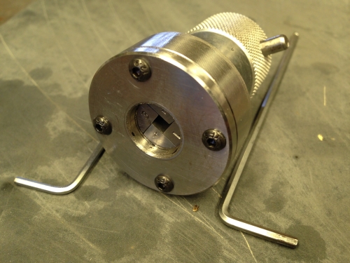
Showing the jaws holding a tap. The jaw cover is removed. The hole in the side of the chuck is for the M5 grub screw which opens and closes the jaws.

Showing the jaws cover in place.

The 3 jaw chuck provides a convenient and accurate base. Alternatively, the guide could be supported in a hole in the bench.

Very handy for tapping threads in items not readily held in a vise.
The biggest problem with tapping threaded holes is taps which break in a job. Sometimes after many, many hours making a part. Sometimes the broken tap is able to be removed, and sometimes it cannot, resulting in a ruined part, wasted time and much wailing and gnashing of dentures.
Keeping the tap vertical at all times during the tapping procedure, and using a sharp tap, suitable lubricant, and appropriate torque, are the keys to not breaking taps and saving teeth.
Usually I do my tapping with the tap held under a spring loaded guide in the chuck of the drill press or mill, and the workpiece in the vise. This method prevents any inadvertent bending of the tap, which avoids one of the major causes of breakages.
But sometimes it is just not possible to hold the workpiece in the mill or drill press and the tapping has to be done freehand, aligning the tap by eye. I am rarely satisfied that the tap is vertical after using this method. Lack of accuracy, and higher chance of a broken tap is the consequence.
So when I saw this tapping guide in “Model Engineer”, and saw the possibilities for its accuracy and versatility, I decided to make one. The fact that much of the machining could be CNC’d was an added attraction. Also the 4 jaw chuck was intriguing. I had seen one made by a colleague in the Melbourne Model Engineering Club, and I was keen to see if I could manage it.
The design was by Mogens Kilde and the plans were published in the August 2015 “Model Engineer”. I made a few minor changes to the design, mainly using thicker aluminium in the arms and flanges. I used stainless steel for the chuck body because that was the only free machining steel which I had in the size. I used key steel for the chuck jaws, again because that was what I had available in my workshop.
The double parallelogram arms keep the tap vertical within the limits of the arm movements. Using a 3 jaw chuck as the base of the unit provides a lot of flexibility in positioning the guide.
I will not comment on the actual building, because that is clearly explained in detail in the original ME articles.
