Bolton No 7 and boiler
by John
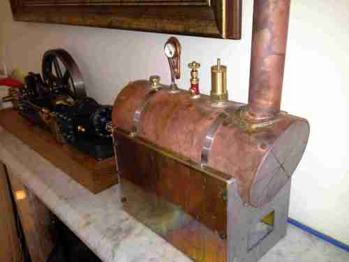
Gas fired 4″ boiler
Bolton No 7, double action, single cylinder stationary steam engine.
I will download a video of the engine operating on steam, soon. Keep watching.

Gas fired 4″ boiler
Bolton No 7, double action, single cylinder stationary steam engine.
I will download a video of the engine operating on steam, soon. Keep watching.

Hi John, I was trying to work out the scale of your machines. Your finger on the square file helped, and also the mention of a 14in. diam. flywheel. in the photo. Great work.
LikeLike
Hi Frank
The Bolton7 and boiler are about 550x150x150 mm. You can see my hand for scale in the video.
The beam engine is 550x200x500 and it weighs a backbreaking 72lbs. 32kg. Not sure where it will eventually live. It will require a bigger boiler than the one in the bolton7 video. I wonder if it will be allowed to remain in the house. My next model engine project will be smaller and hopefully a bit lighter!
LikeLike
Hello there John,
I found your site when doing a google search on the Bolton #7
I am retired and having finished a “wobbler”, have started a #7.
I have machined the base and agree that clamping and machining irregular castings correctly is so important. Lots to come!
Many thanks from me for the time you give to the blog and for the education and encouragement it provides.
It would be great to hear more from Bolton #7 builders
Kind regards,
Tim
LikeLike
Hi Tim, the Bolton 7 was my first model engine, and I must warn you that engine building is an addiction! John. Good luck!
LikeLike
Hi John,
I have a question if I may.
I have machined the underside of the bedplate (twice) It is .0197″ (0.5mm) higher at the cylinder end.
This would result in the clearance under the cylinder (which on the plan is 1/16″ (.0625″)) reduced to .0428″.
if this slightly reduced clearance matters I will machine the bedplate a third time but do not want to do so if it’s not necessary.
I can’t see that this slight reduction matters but would value any comment (even to the contrary!)
Cheers, Tim
LikeLike
Tim, I doubt that small discrepancy will matter. I noticed when I machined the bedplate that it developed a bend, probably by releasing inbuilt stresses in the cast iron. Repeated passes did not fix the problem, so I eventually accepted it. It did not matter. In fact I had totally forgotten about it until I read your comment. You might need to use shims to align parts in the final assembly
John
LikeLike
Thanks John that’s very interesting. I did a third pass and the fractional “warp” is my experiemce too.
Thankfully I have completed the bedplate now and happily all the pad levels align.
And so to the cylinder…
Kind regards.
Tim
LikeLike
Hi John,
I sent a reply earlier but can see no evidence of it so my apologies if this is a repeat.
Having machined the #7’s bedplate (twice) I’m looking at a slightly reduced clearance under the cylinder – .5mm less than the 1/16″ on the plan.
If this doesn’t matter I’ll proceed. If it does I’ll do another correcting milling pass on the bottom of the bedplate.
I cant see that it matters so long as the levels under the cross head and the crankshaft are accurate.
I’d hate to be wrong!
Any comment?
LikeLike
see previous reply Tim
LikeLike
Hi there John,
It’s 7 builder Tim here.
As per E Winter’s instructions, I have measured the cylinder casting carefully and noted the amount and placement of machining allowances.
The only way I can accommodate these with the material available, has the vertical C/L drawn 1/16″ off center along the bolting face.
I’m wondering if you can remember whether this was your experience as well.
Regards,
Tim
LikeLike
Tim, I have a very vague memory that I might have put a brass shim under the cylinder. I can barely remember what I did yesterday, so please do not hold me to this. John.
LikeLike
Thanks for the prompt reply John.
I’m sorry to tax the grey cells when you have moved so far on from the #7.
I’m probably being a nervous Nelly about minor matters.
I watch your website with much intetest and admiration.
Cheers, Tim
LikeLike
Good afternoon John,
It’s Bolton 7 Tim here with a question.
I have faced the flywheel end of the cylinder the and am turning its flange.
I couldn’t get a clear look at your model to see whether you turned past the flange and all the way to the edge of the valve face part of the casting.
If you did then you would also have turned a fair bit of material from the cylinder’s bolting face, reducing it’s length.
Put simply…How far in did you turn the flanges?
I hope this is easily answered and not a nuisance.
Kind regards,
Tim
LikeLike
Hi Tim, if I understand your question correctly, I appear to have turned the flange back to the edge of the valve case. I took a photo, and will post it on the blog. I don’t seem to be able to attach photos here. John
LikeLike