machines which I have made, am making, or intend to make, and some other stuff. If you find this site interesting, please leave a comment. I read every comment and respond to most. n.b. There is a list of my first 800 posts in my post of 17 June 2021, titled "800 Posts"
300pd Blackpowder Cannons at Williamstown
by John
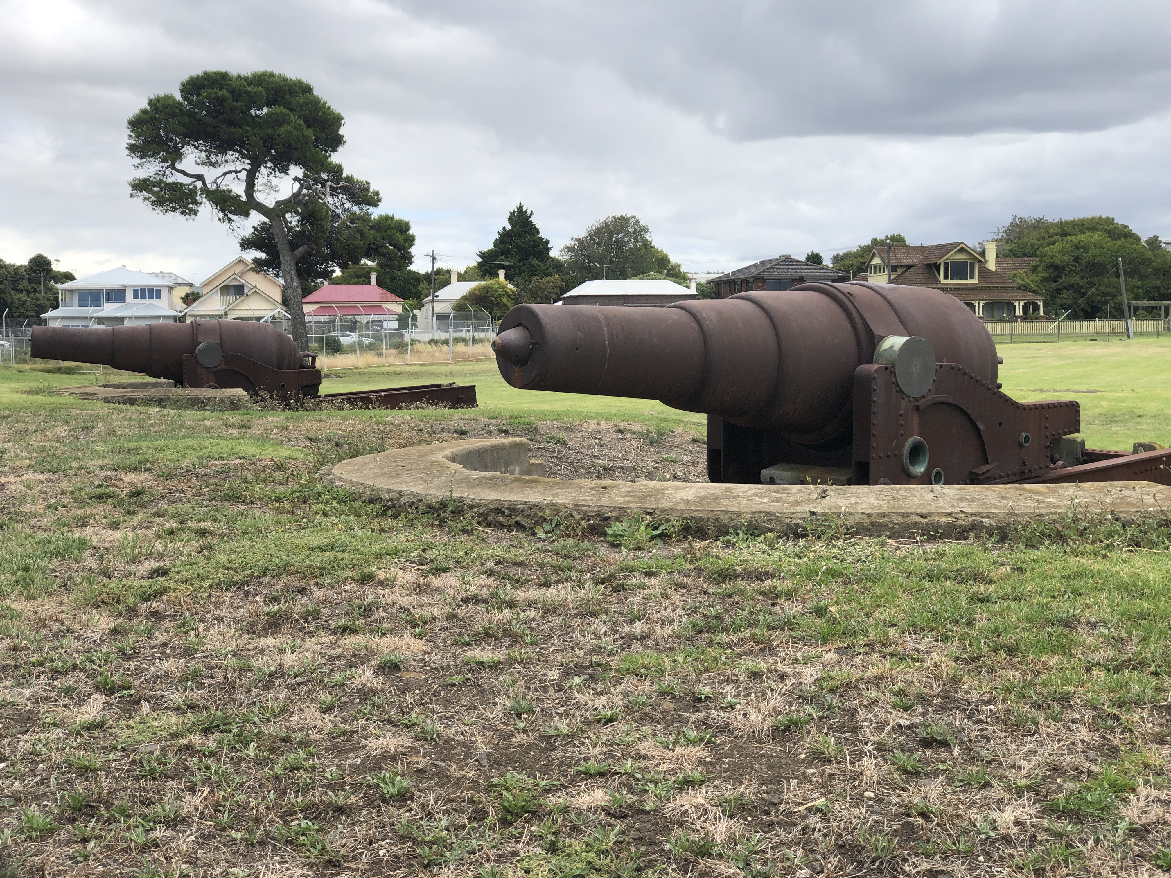
The cannon construction techniques which were pioneered by William Armstrong in the 1860’s led to more powerful and more accurate weapons. The 6.3″/160mm bore cannons which were shown in yesterday’s post, (and modelled by me,) were rapidly followed by larger cannons. The larger cannons were required to counter the iron clad steam ships which were replacing wooden warships. The colony of Victoria purchased 9″ muzzle loading black powder cannons for the defence of Melbourne, and yesterday I visited Williamstown to see 4 of them.
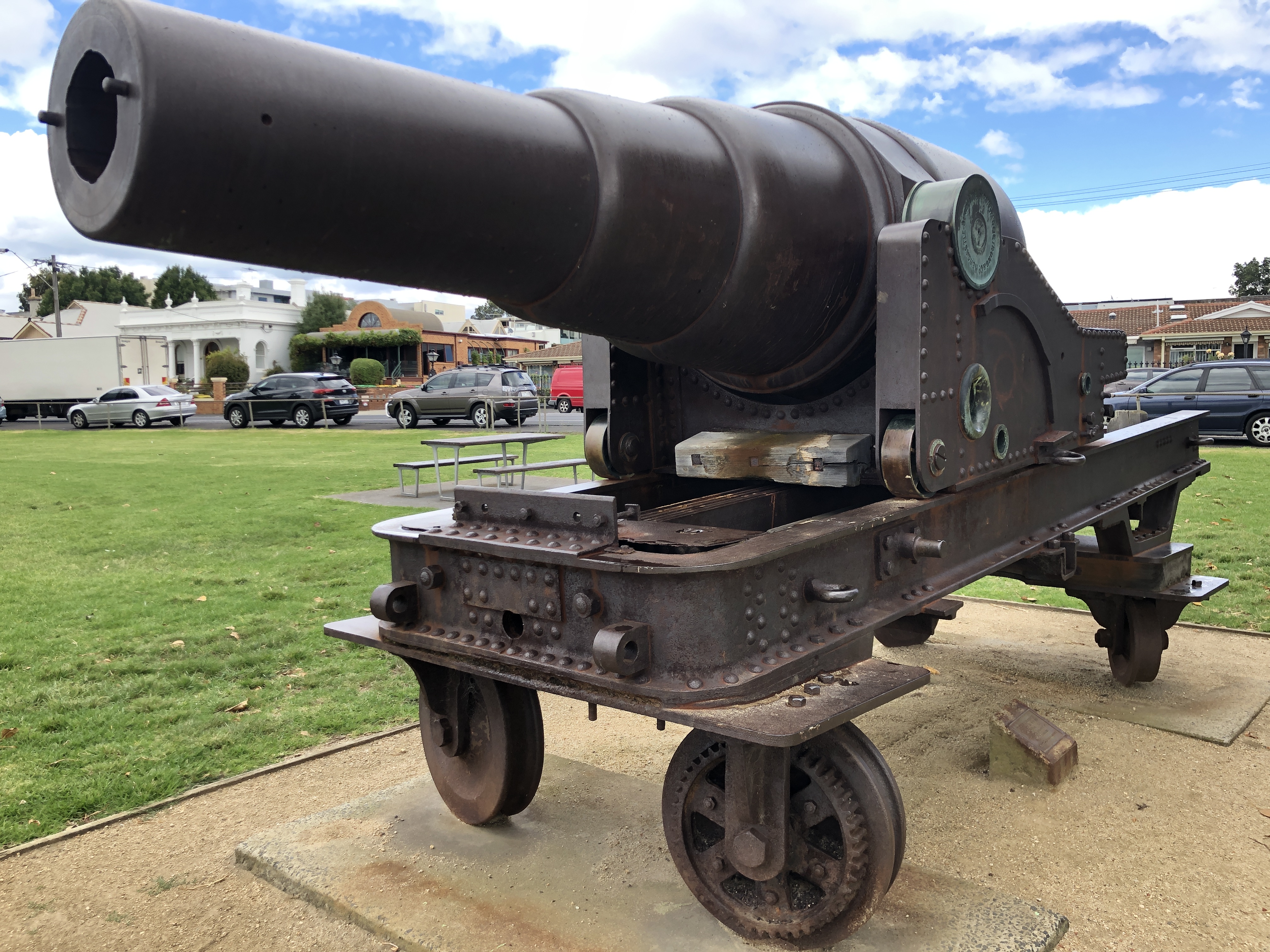
The 9″ rifled bore cannons fired projectiles weighing 300lbs! Cannons of this size were described according to the bore diameter, in preference to the weight of the projectile.
A fort was constructed at Williamstown (Fort Gelibrand), and 2 of the cannons are located inside a military establishment, unfortunately not accessible to the public.
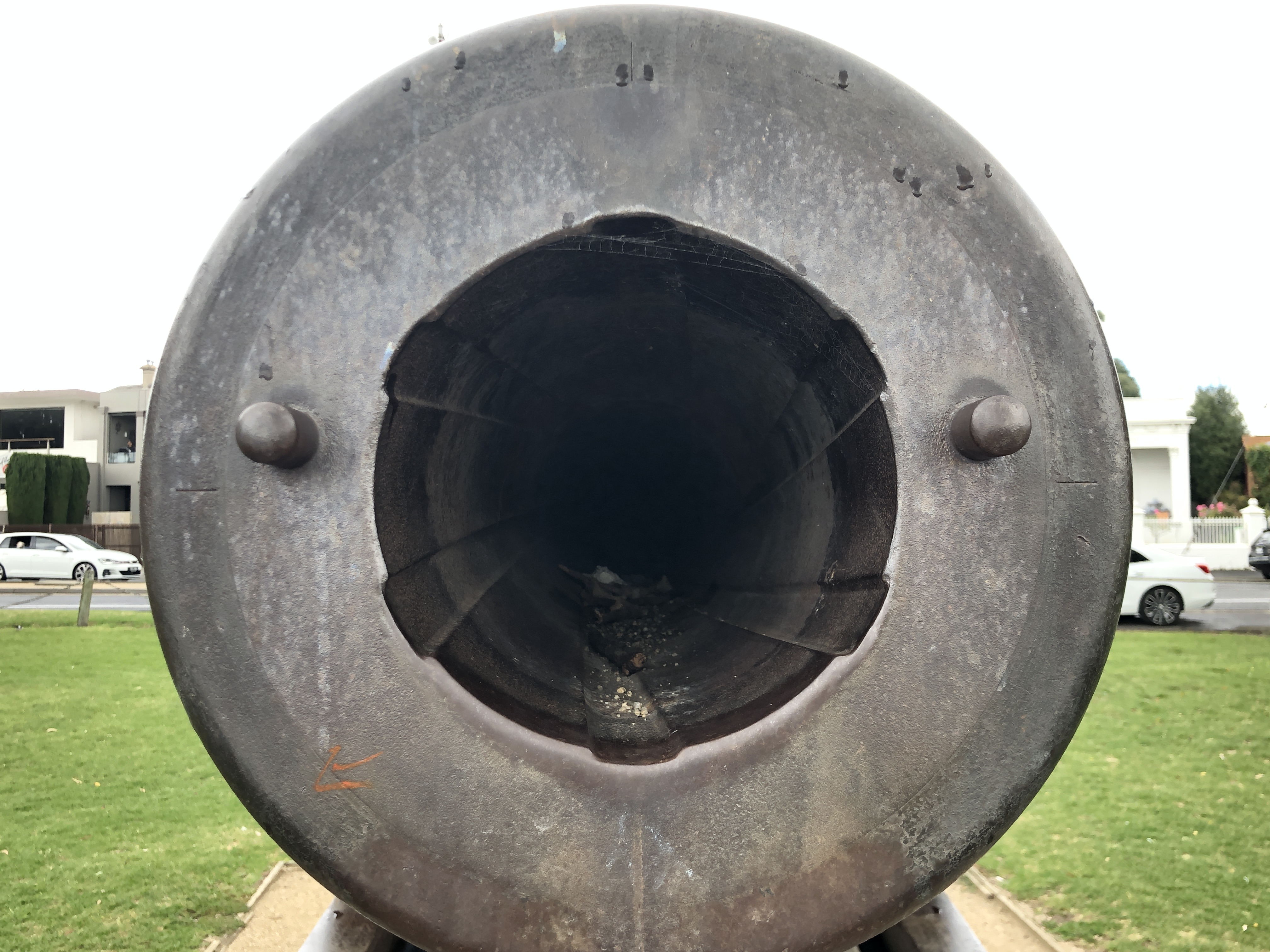
As seen from about 20 meters, through the fence. Muzzle loading 9″ monsters. The projectile seen is said to be stuck there.
I was sure that I had seen some photographs of similar guns at Williamstown which were accessible so I asked some locals, and was directed to the foreshore.
That is Melbourne CBD in the background.
These 9″ guns are rifled (6 grooves), made in 1867, and muzzle loading blackpowder. They are very similar to the 10″ guns which were mounted on the monitor HMVS Cerberus, but these are garrison mounts whereas the Cerberus guns were rotating naval mounts.
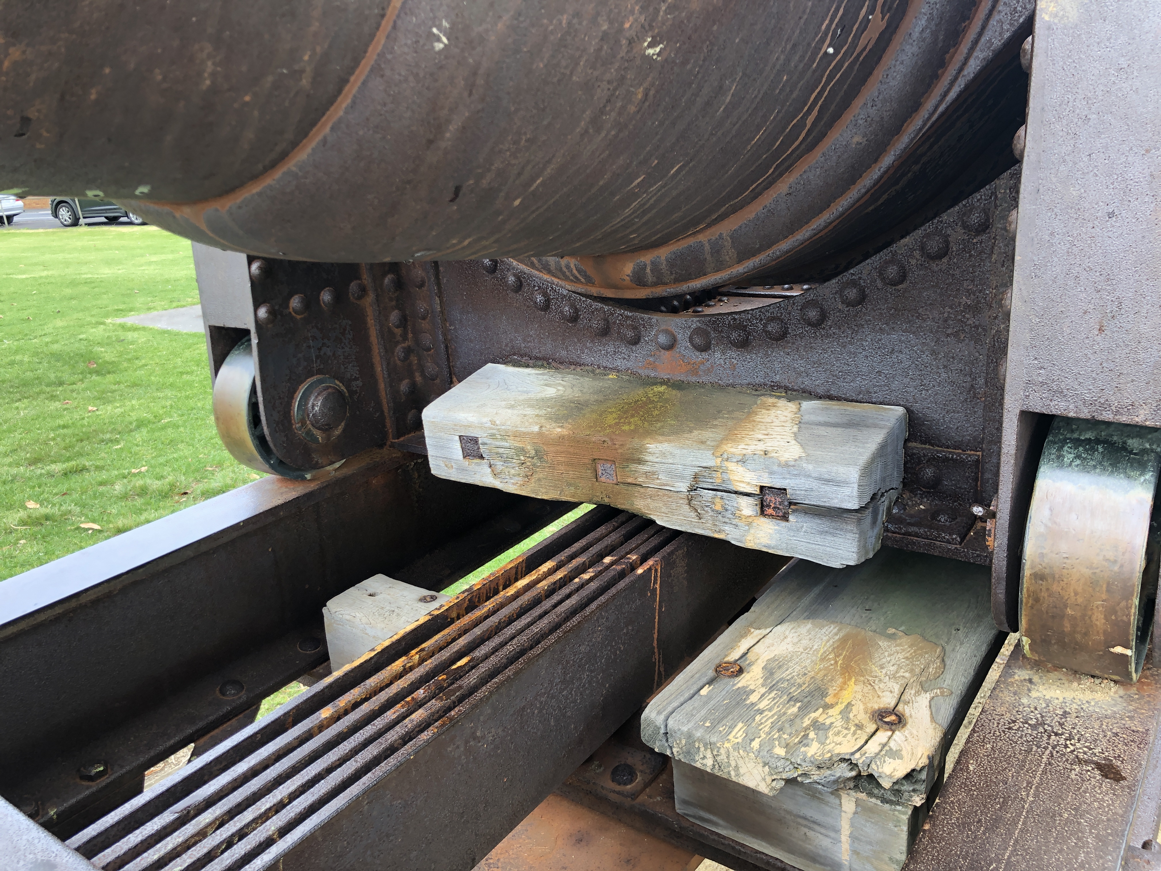
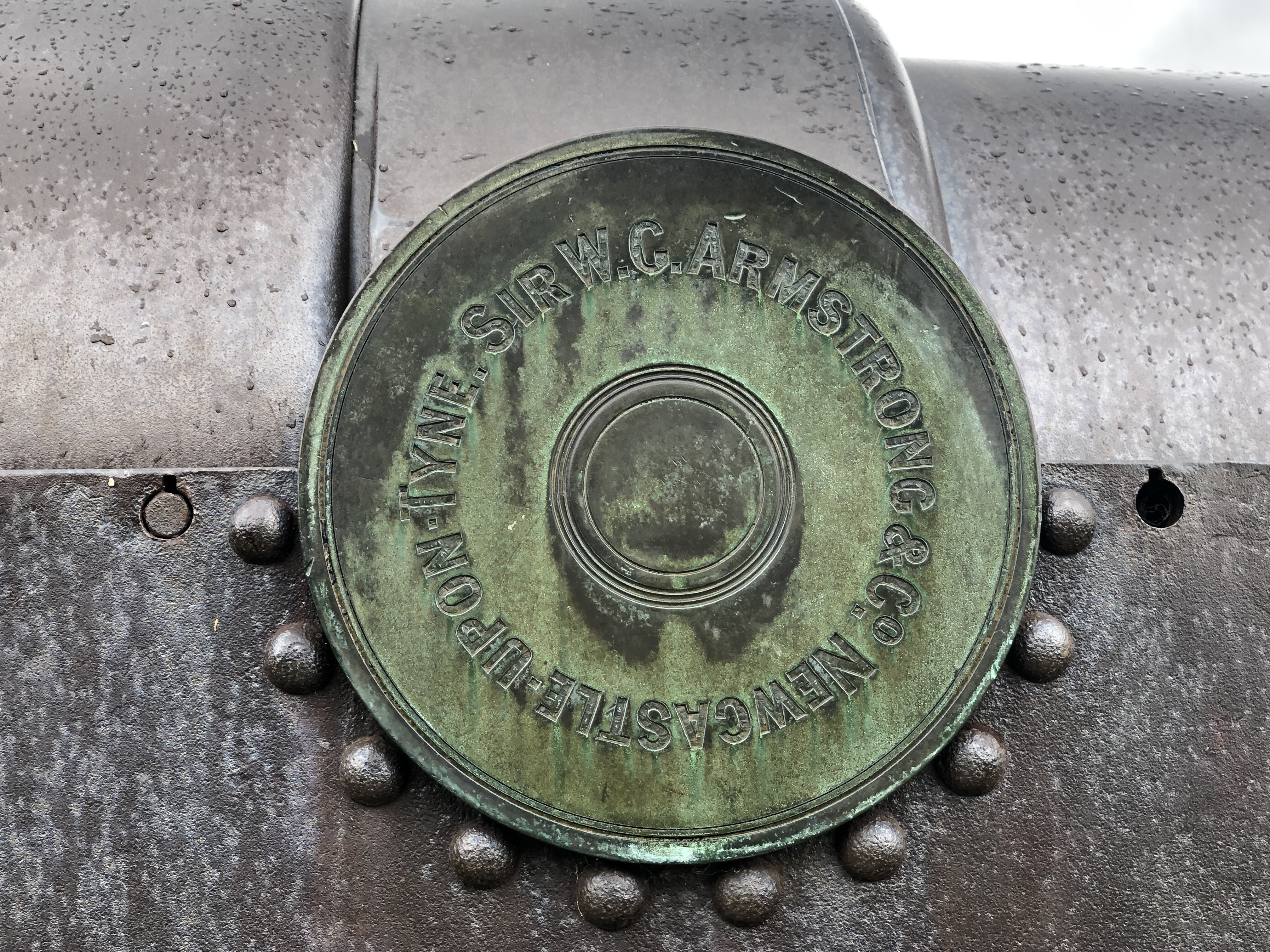
The 300lb projectiles were loaded using a gantry which was mounted on the end of the barrel. The gantry mounting point can be seen as the small holes in the side of the barrel.The loading gantry can be seen in this old photograph of one of the 9″ Armstrongs when it was located at Fort Queenscliffe.A feature of the 9″ cannons was the “Elswick” recoil control mechanism. These substantial strips of iron extended the length of the chassis, and shorter pieces of iron were hung from the carriage to provide friction control of the recoil. The degree of friction was controlled with levers which adjusted the spacing of the strips.Unfortunately most of the elevation control mechanisms are missing. The small bracket top left was probably to hold the steel rod which was used to perforate the gun powder bag after it and the projectile were positioned.6 rifling grooves. The projectiles 1867 to 1877 would have had studs to match the rifling. After 1877 the projectiles would have used copper gas checks to engage with the rifling. The inner and outer coil layers of the chase of the barrel can be seen if you look closely.The 9″ guns were manufactured at the Elswick works, Newcastle, England. and the Royal Gun Factory Woolwich England. The gunmetal trunnion caps are original. If you look closely at the barrel surface you can make out the outlines of the strips of iron which formed the coils.
HMVS Cerberus is a topic for future posts. An excellent source of information is found at http://www.cerberus.com.au
Been inside Fort Gellibrand, on numerous occasions, day & night. (scary meeting the resident Commandos in the dark,) I think the reason you can’t get to the cannons is that they’re still in working order and carried around by the commandos on dark nights.
A great effort & beautiful workmanship. Just a few comnents, I believe that to operate the running back gear a crank handle may have been used instead of a wheel as your model shows. On the internet a video shows a detatchment demonstrating running back of a 64 Pdr RML gun at Fort Lytton as part of their firing drill. Also there are two L shaped brackets fitted on each side on the gun slide they support timber platforms. I believe. Lyttons 64 Pdrs show these as well.
Thanks Greg, I am currently completing another 80pr Armstrong 1:10 model for myself, and on this one I have included the timber platforms and brackets. WRT the running back handles, The round wheel handle copies the 80pr Armstrongs at Warrnambool. None of the other 80pr’s in Victoria have handles at all. Cranks would have been less expensive, and easier to remove for firing, transport etc. so I agree that they are more likely to be the original system. The 80pr version of the 6.3″ RML seems to have been unique to Victoria, as it is not mentioned at all in any of the references for RML’s from the RGF which I have been able to source. The operating manual for the 80Pr does not mention the running back handle shape wheel/crank. None of the old photos of 80Pr’s show either pattern. At this time I have made wheels again, but I have pondered the possibility of making cranks. If you have any old photos of 80Pr’s showing cranks/wheels I would love to see them.
Hi again Greg, I delved a bit further into the crank vs wheel for the running back gear, by reading the instruction manuals for the 64pr and 80pr Armstrong RML’s. I found a simple line diagram for the 64pr and there is no doubt that it used cranks on both sides for running back. The situation for the 80pr is a bit less definite because the diagram does not show the crank/wheel at all, and the instructions give no clue. I am left with the existing wheels on the Warrnambool 80pr RML’s and wondering whether the wheels are later restoration guesses, or whether they had some old photographs, or indeed whether they are original components. The chassis/slides for the 64 and 80prs show a few differences, so it is not inconceivable that the makers might have changed the running back gear for the 80’s. For my current model I have already made a pair of wheels, but I will probably make a pair of cranks, just in case some more info comes to light. John
HI JOHN IF MEMORY PROVES CORRECT SEVERAL OF THE 80 Pdrs PPSSIBLY FROM PORTLAND WENT TO THE BENDIGO ORDNANCE FACTORY TO BE WORKED ON AT THE APPRENTICE TRAINING SCHOOL. I THINK THEY ASSUMED THAT THAT THE RUNNING GEAR WAS OPERATED BY A WHEEL & HAD THEM MADE ACCORDINGLY. THEY LOOK IDENTICAL TO THE HAND WHEELS THEY MADE FOR OUR 80 Pdrs IN WOLLONGONG TO ENGAGE THE ELEVATION MECHANISM. I FOUND OUT LATER THAT THEY WERE NOT ACCURATELY MADE FOR OUR GUNS, OURS IT SEEMS WERE SMALLER IN DIAMETER & HAD FIVE SPOKES PLUS THEY WERE FITTED WITH A HANDLE FOR WINDING IT AROUND. REGARDS, GREG


Been inside Fort Gellibrand, on numerous occasions, day & night. (scary meeting the resident Commandos in the dark,) I think the reason you can’t get to the cannons is that they’re still in working order and carried around by the commandos on dark nights.
LikeLiked by 1 person
yeah, but my uniform stopped fitting about 40 years ago.
LikeLiked by 1 person
A great effort & beautiful workmanship. Just a few comnents, I believe that to operate the running back gear a crank handle may have been used instead of a wheel as your model shows. On the internet a video shows a detatchment demonstrating running back of a 64 Pdr RML gun at Fort Lytton as part of their firing drill. Also there are two L shaped brackets fitted on each side on the gun slide they support timber platforms. I believe. Lyttons 64 Pdrs show these as well.
LikeLike
Thanks Greg, I am currently completing another 80pr Armstrong 1:10 model for myself, and on this one I have included the timber platforms and brackets. WRT the running back handles, The round wheel handle copies the 80pr Armstrongs at Warrnambool. None of the other 80pr’s in Victoria have handles at all. Cranks would have been less expensive, and easier to remove for firing, transport etc. so I agree that they are more likely to be the original system. The 80pr version of the 6.3″ RML seems to have been unique to Victoria, as it is not mentioned at all in any of the references for RML’s from the RGF which I have been able to source. The operating manual for the 80Pr does not mention the running back handle shape wheel/crank. None of the old photos of 80Pr’s show either pattern. At this time I have made wheels again, but I have pondered the possibility of making cranks. If you have any old photos of 80Pr’s showing cranks/wheels I would love to see them.
LikeLike
Hi again Greg, I delved a bit further into the crank vs wheel for the running back gear, by reading the instruction manuals for the 64pr and 80pr Armstrong RML’s. I found a simple line diagram for the 64pr and there is no doubt that it used cranks on both sides for running back. The situation for the 80pr is a bit less definite because the diagram does not show the crank/wheel at all, and the instructions give no clue. I am left with the existing wheels on the Warrnambool 80pr RML’s and wondering whether the wheels are later restoration guesses, or whether they had some old photographs, or indeed whether they are original components. The chassis/slides for the 64 and 80prs show a few differences, so it is not inconceivable that the makers might have changed the running back gear for the 80’s. For my current model I have already made a pair of wheels, but I will probably make a pair of cranks, just in case some more info comes to light. John
LikeLike
HI JOHN IF MEMORY PROVES CORRECT SEVERAL OF THE 80 Pdrs PPSSIBLY FROM PORTLAND WENT TO THE BENDIGO ORDNANCE FACTORY TO BE WORKED ON AT THE APPRENTICE TRAINING SCHOOL. I THINK THEY ASSUMED THAT THAT THE RUNNING GEAR WAS OPERATED BY A WHEEL & HAD THEM MADE ACCORDINGLY. THEY LOOK IDENTICAL TO THE HAND WHEELS THEY MADE FOR OUR 80 Pdrs IN WOLLONGONG TO ENGAGE THE ELEVATION MECHANISM. I FOUND OUT LATER THAT THEY WERE NOT ACCURATELY MADE FOR OUR GUNS, OURS IT SEEMS WERE SMALLER IN DIAMETER & HAD FIVE SPOKES PLUS THEY WERE FITTED WITH A HANDLE FOR WINDING IT AROUND. REGARDS, GREG
LikeLike
Thanks Greg, that information nails it! I will be sticking with handles, not wheels. (a pity, because the wheels look rather spectacular). John.
LikeLike