
Mini 4 Axis CNC Mill-8. Finished!
by John
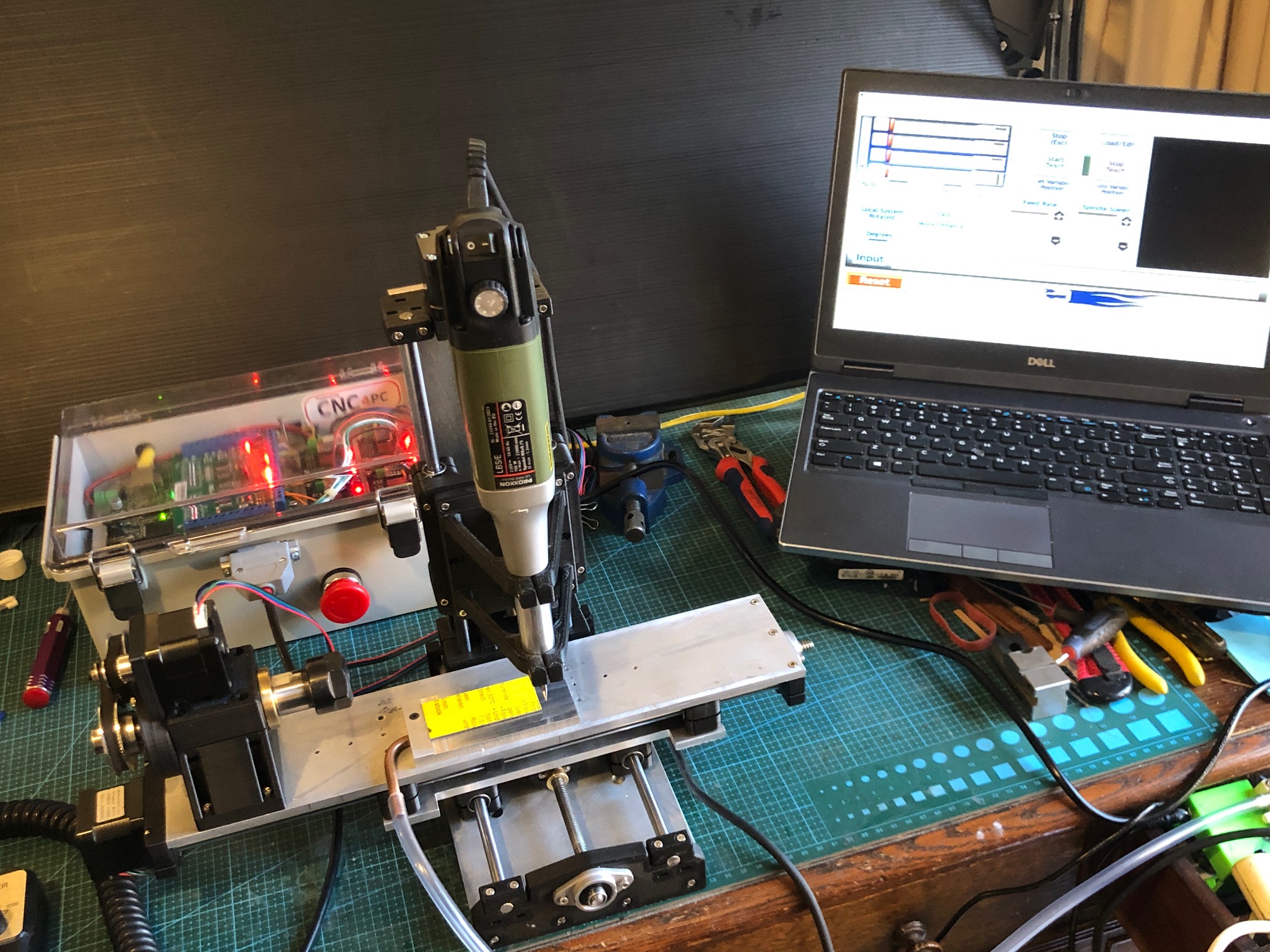
I have finished the Mini CNC Mill. It is working, and I am satisfied that it will do the jobs of making small 3D pieces accurately.
Had to sort a few problems. First there was excessive play between the hardened steel 8mm rods and the linear bearings. I had measured the rods at 7.97mm diameter, so placed another order, and eventually received some slightly better rods, at 7.985, but no improvement in the play, so placed yet another order, (different supplier each time), and the final ones were 7.99, and still the play was excessive. Then the penny dropped, and I got some new linear bearings, which solved the play problem.
Next issue was excessive backlash in the acme screw nuts, but that was solved by installing them correctly, after some advice from my engineer friend Stuart. But it did involve a complete tear down of the machine several times before I did it properly.
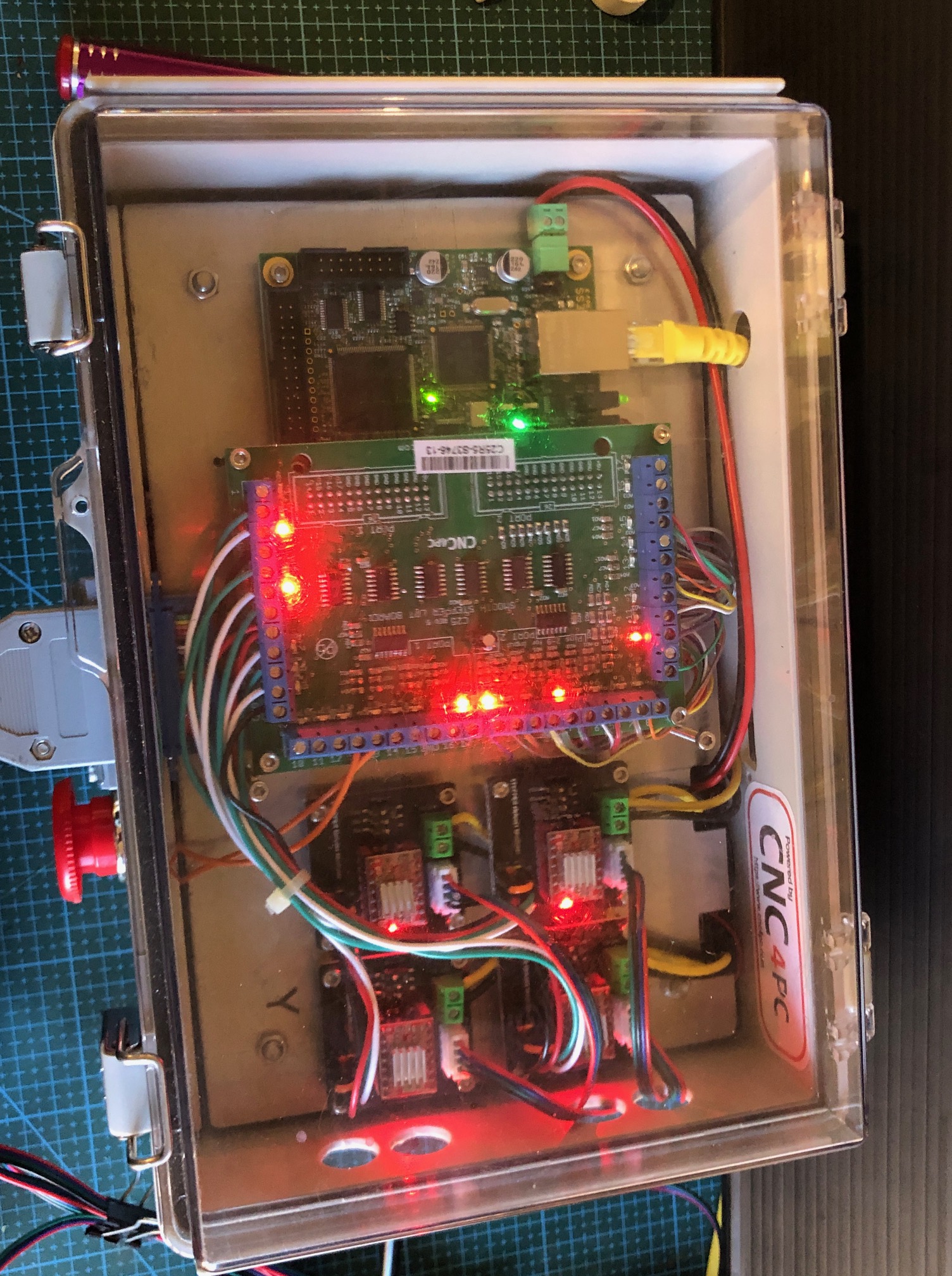
Finally, I installed all of the boards, switches, power supply, fuse, in the electronics control box. That was fairly straight forward, but I knew that I was not capable of doing the wiring and booked my expert friend Stuart to do the job for me. Despite the fact that he has done the same installation on many occasions, it took him about 4 hours. I was taking frequent photos and making copious notes, so I could post that information here, but frankly, despite having a reasonable understanding of the principles of the workings, when issues arose on first testing, I had no idea how to do the trouble shooting, or how to fix the diagnosed problems. Stuart however sorted the issues quickly and efficiently. ( I imagine that if I was teaching Stuart how to do a Caesarean Section or a hysterectomy, the roles would be reversed.)
So, I am not going post the details of the electronics wiring. But I will post photos of the completed job. (see below).
If anyone does decide to go down a similar path, and is not an electronics expert, my strong advice is to have an expert do that part of the job. It is not for amateurs. The making of the mill, and installation of the electronics components was simple compared to the wiring.
The mill is accurate and adequately rigid for 3d machining of plastic, wood, aluminium and brass parts, using cutters up tp to 3mm diameter.
The final cost of the mill and the electronics control box and manual handpiece, excluding repeat purchases due to quality of some components, was approx $AUD1000. That does not include Mach3 and Vectric V Carve Pro which I had purchased several years ago.
When I make some model ship building components I will post some videos and pics.
The most expensive component was the electronics box of controls (ESS board, breakout board, stepper motor control modules, switches etc) which was about 2/3 of the total. But with all of those red and green LED’s it is quite a nice display!
Although “finished”, I am planning to add a sacrificial wooden work surface, and a tailstock for the 4th axis rotary table. I think the tailstock will be useful for example for making spars.
And, I will be able to use the electronics box to run the CNC serving machine which is well underway. Again, waiting for components, this time from China.
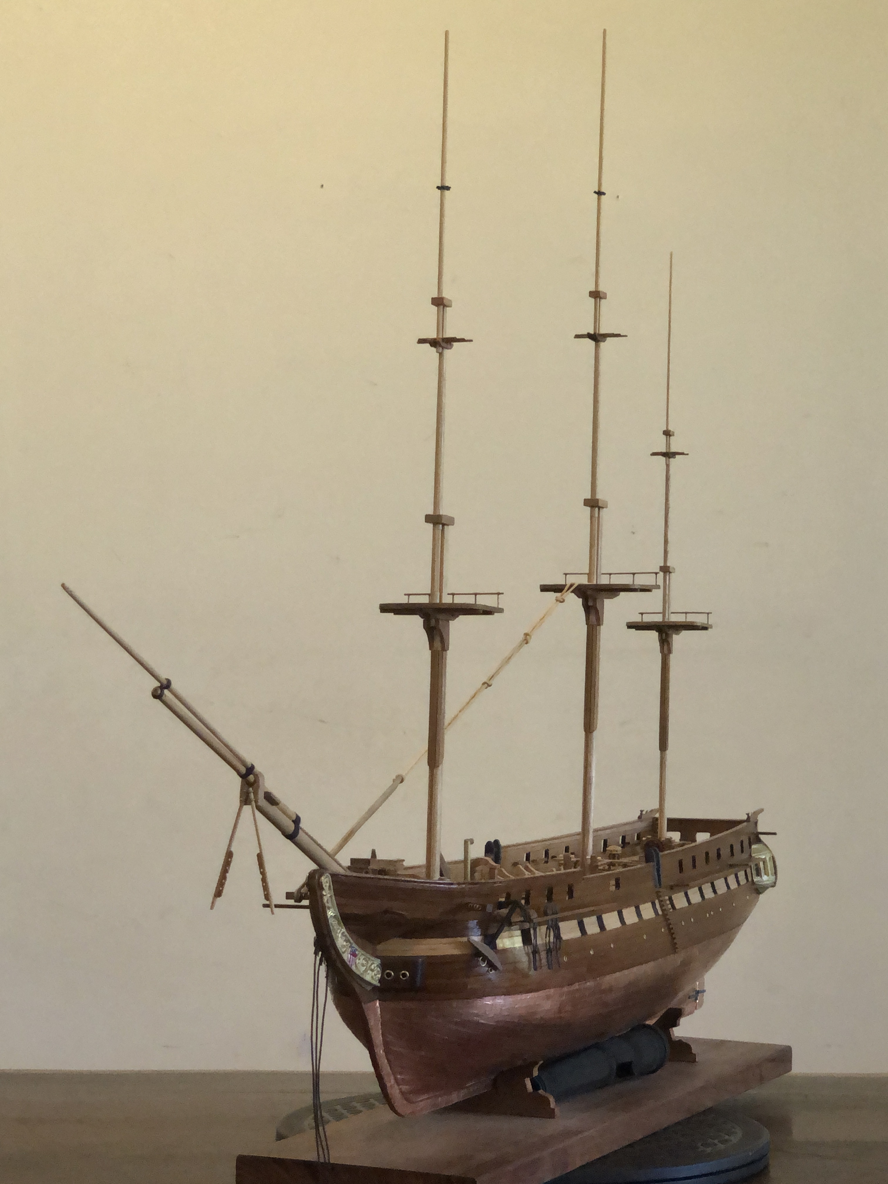
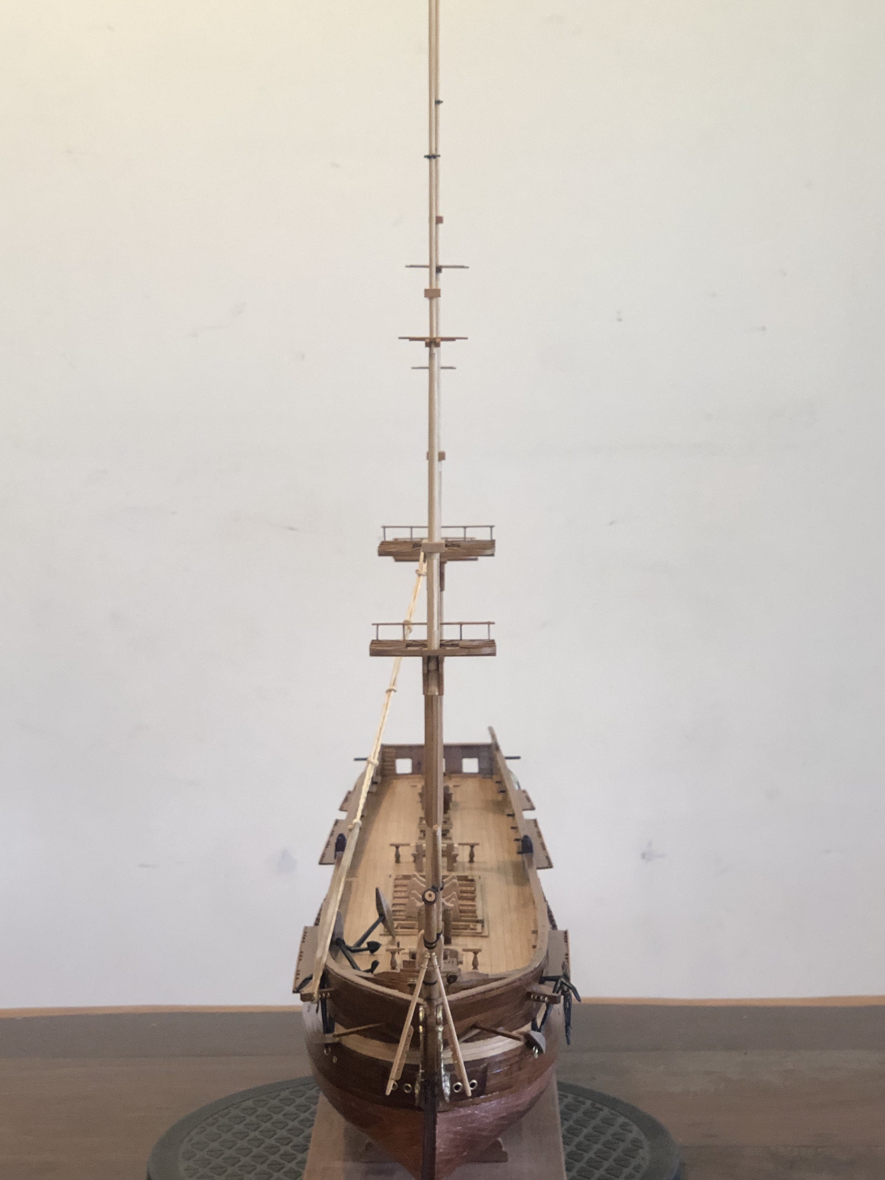
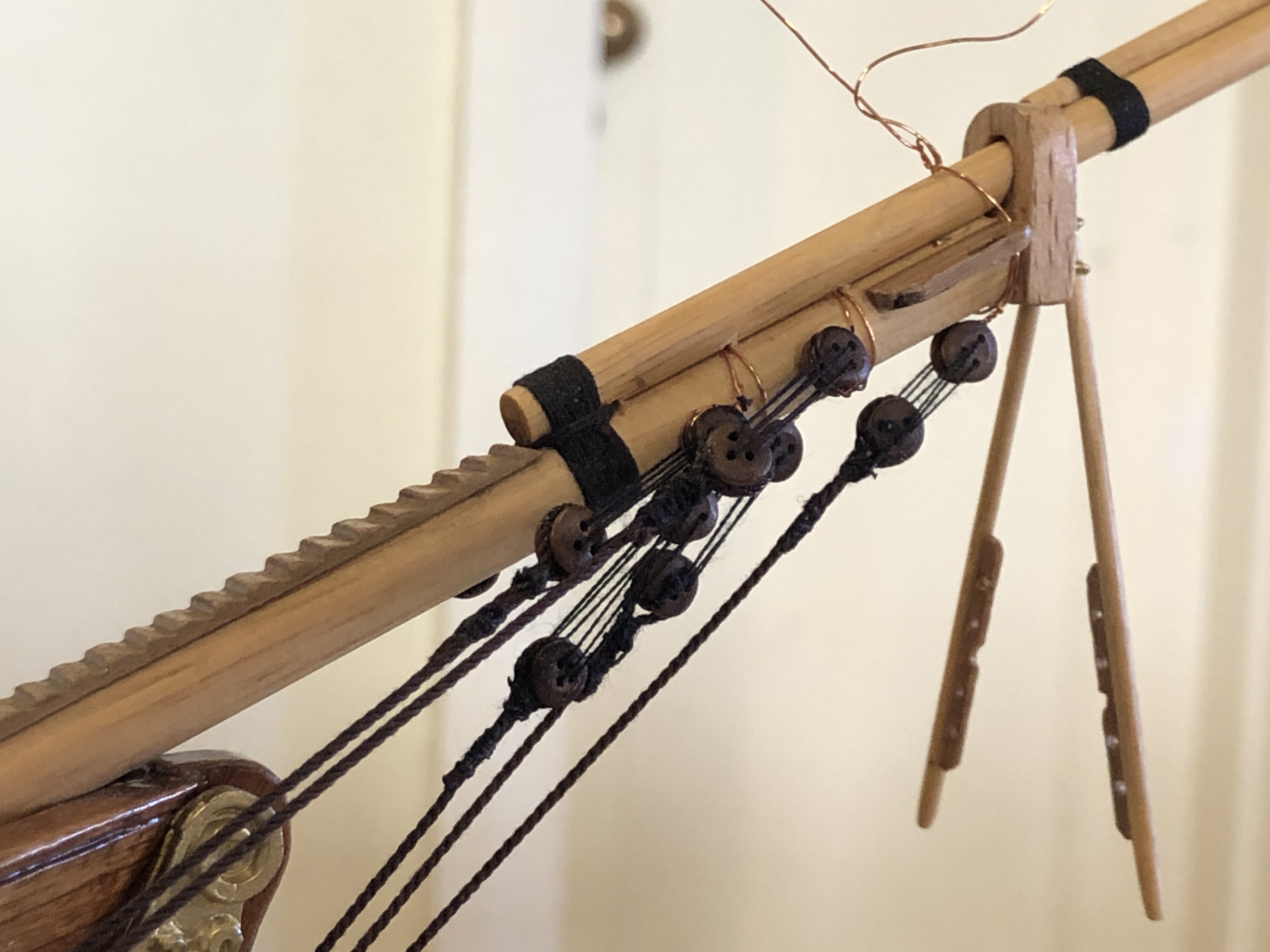
And some progress on the Constitution. I have made the masts and bowsprit, and they are now siting in position, ready for the standing rigging.

Hello from Colorado, USA! I have read your entire Constitution blog. I received the same Mamoli kit from a neighbor last year. He gave me two kits that he found when cleaning out his sister’s things. Like yours, mine had never been opened. I copyright on the paper work was 1982 with a price of $149.98 on the box. I am not quite as far along as you are. BTW, your work is amazing and your photo work is top notch as well. I have a few questions and could some advise. My first question involves the planking on the hull below the poop deck. This would be Figures 13 and 14 on the second sheet of instructions. Part 49 is flat with nothing in the instructions that say it should be bent. I see the beautiful job you did planking this area. Do you have some pics of how you did that? I gave up on that for the time being and moved on to Instructions Page 3. I am through Page 3 and am working on the last thing – the metal pieces making up the stern windows on each side. I am assuming that the wood supports that were part of the stern cabin and sticking out on the hull need to be removed. Strange how they would not include that in the instructions. Finally, did you heat the window frames to match the curvature of the upper and lower pieces? I like your idea of JB Weld to get them to stay together. I am a bit concerned about attaching the three piece window set to the hull. I noticed you said you were saving that for later. If you have a few minutes, I would appreciate a reply. Thanks! Bruce email: brucelinafelter@gmail.com
LikeLike
Hi Bruce, and thankyou for the nice feedback.
I did not bend part 49. I think the curved appearance on the plan drawing is that 2 of the edges are glued to curved surfaces and that gives the appearance of part 49 being curved. But remains flat. I recall mulling over that one for quite a while also.
I can’t definitely remember the stern side cabin wood supports. After reviewing my photos, it appears that if you are referring to the horizontal plywood supports, I did gradually trim parts of them away, leaving as much as possible, in order that the metal window assemblies would fit onto the hull.
I did not heat the gallery window frames. That would risk disaster IMO. I do recall spending quite a few hours gradually grinding the parts with a Dremel so they fitted together reasonably. I filled gaps with JB weld, as well as gluing the parts together. Then there was more gradual grinding to fit the glued assemblies to the hull and transom. I painted the assemblies before fitting the “glass” and before gluing the assemblies to the hull.
With the sharply bent hull planks at the bow, I bent them to shape using the tool which I showed earlier on the blog, and glued them from the bow working backwards. I used CA glue for the plank to the first few bulkheads, hand holding until the glue set, (about 30 seconds) and Gorilla glue for the rest of the bulkheads. It was tricky. My first kit build.
I guess that your gun ports are glued into place already. I hope that yours are more accurate than mine. I ended up cutting about half of them out, and regluing them. The worst aspect of the Mamoli kit IMO.
I would suggest that before finishing the hull and deck planking that you glue some supports beside the keel if you intend to use metal supports for the finished model (unfortunately I did not do this). And also some reinforcing inside the hull where the shroud chain plates attach to the hull planking. ( I did not do that either, unfortunately).
I hope that this is helpful. I am still very much a beginner, but happy to describe how I dealt with various issues.
Kind Regards
LikeLike