machines which I have made, am making, or intend to make, and some other stuff. If you find this site interesting, please leave a comment. I read every comment and respond to most. n.b. There is a list of my first 800 posts in my post of 17 June 2021, titled "800 Posts"
Byrnes Style Saw Bench
by John
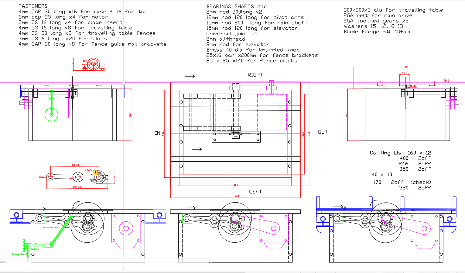
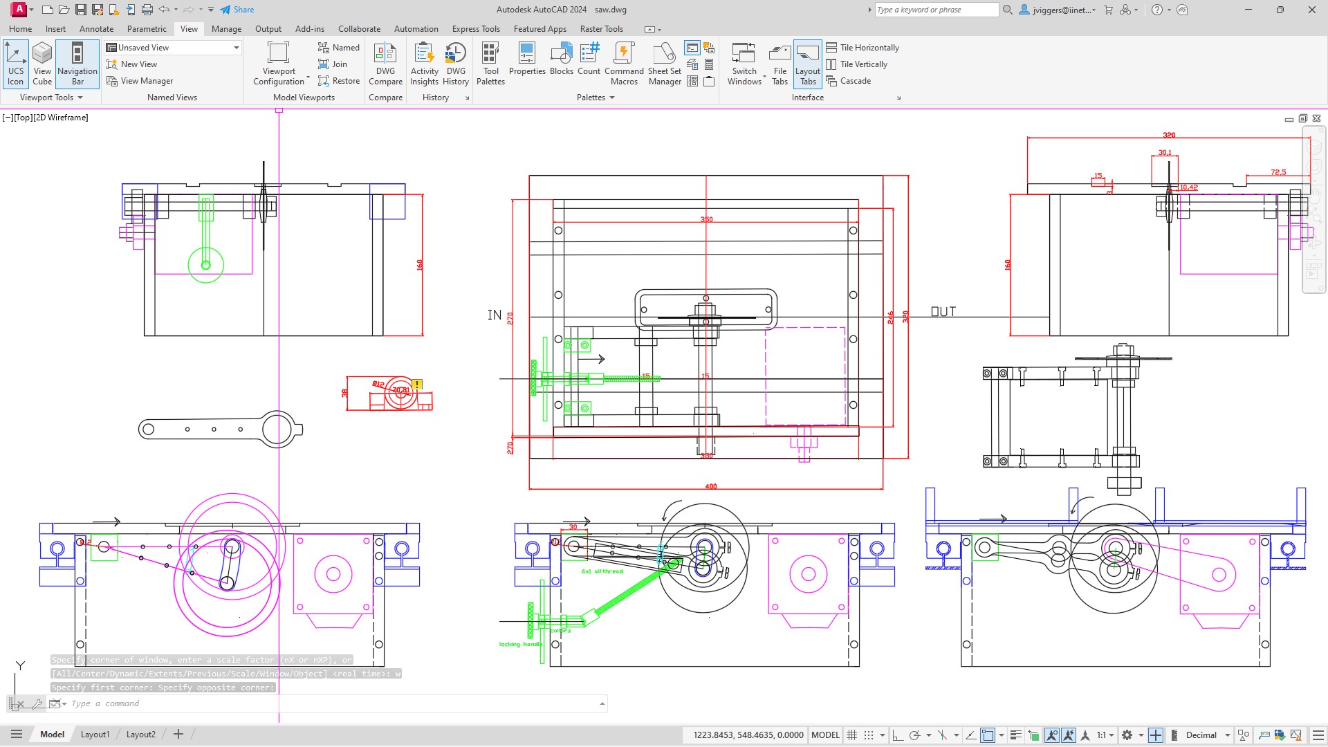
After working on AutoCAD and SolidWorks plans of my intended saw bench, and making multiple revisions, I have made progress on the actual saw.
I also have a ship modelling friend who has a Byrnes saw which he uses for ship modelling. Recently I visited him and asked for his frank assessment of the saw. It was generally very lauditory, but there were 2 aspects which he felt were not optimal. He felt that the table distance behind the blade was too short, and that the motor was a bit underpowered.
So I addressed those details in my design. I added 100mm to the table behind the blade, and used a motor of 750w compared to 200w (I think) in the original. My motor will be an AC Servo with soft start, and electronic braking. It will also be reversible, not that there will be any need for it to be reversed.
My first design. Quite a few changes since then, but the basics remain. The table is 320mm wide, and 400mm long. (The Byrnes version is 300 x 300). The biggest change is the AC servo motor which is enclosed inside the base box.A later design. The maximum saw blade size has been incresed to 120mm diameter, the arms made stronger, and with a heavy plate bolted between the arms, rather than just a steel rod.
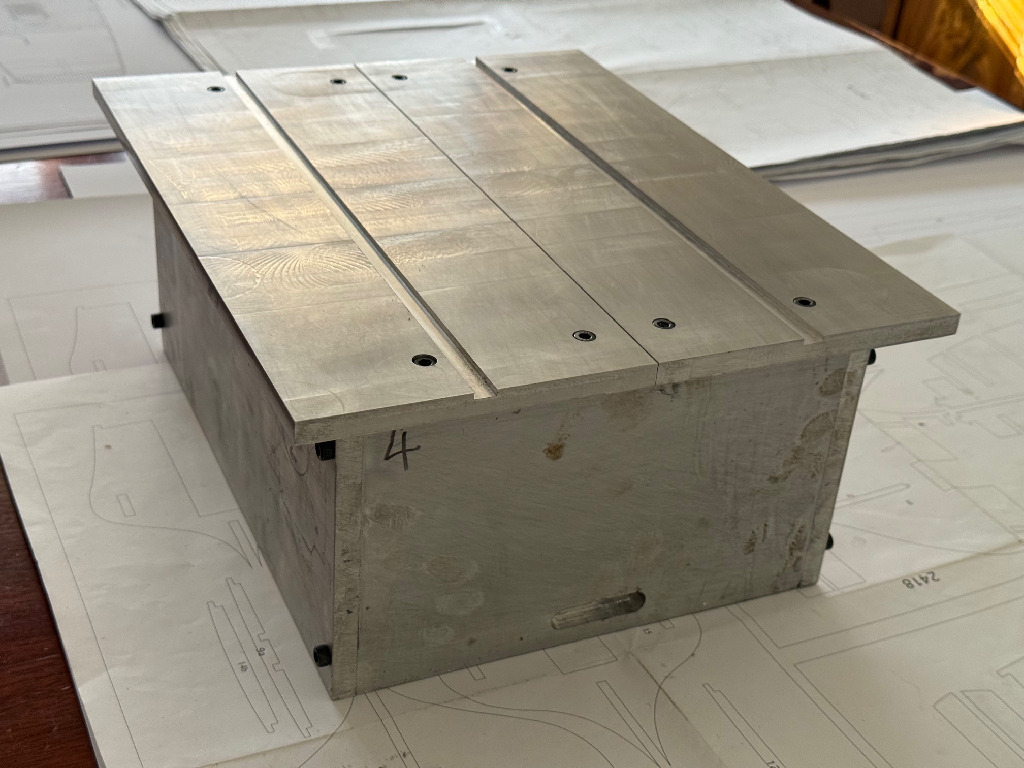
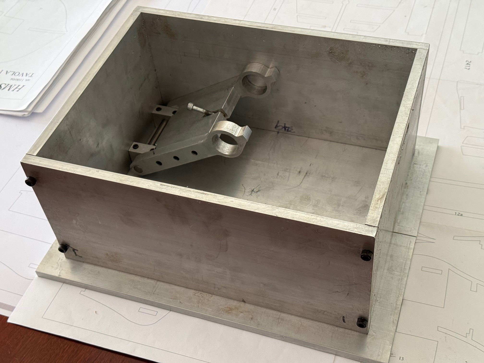
Then construction began….
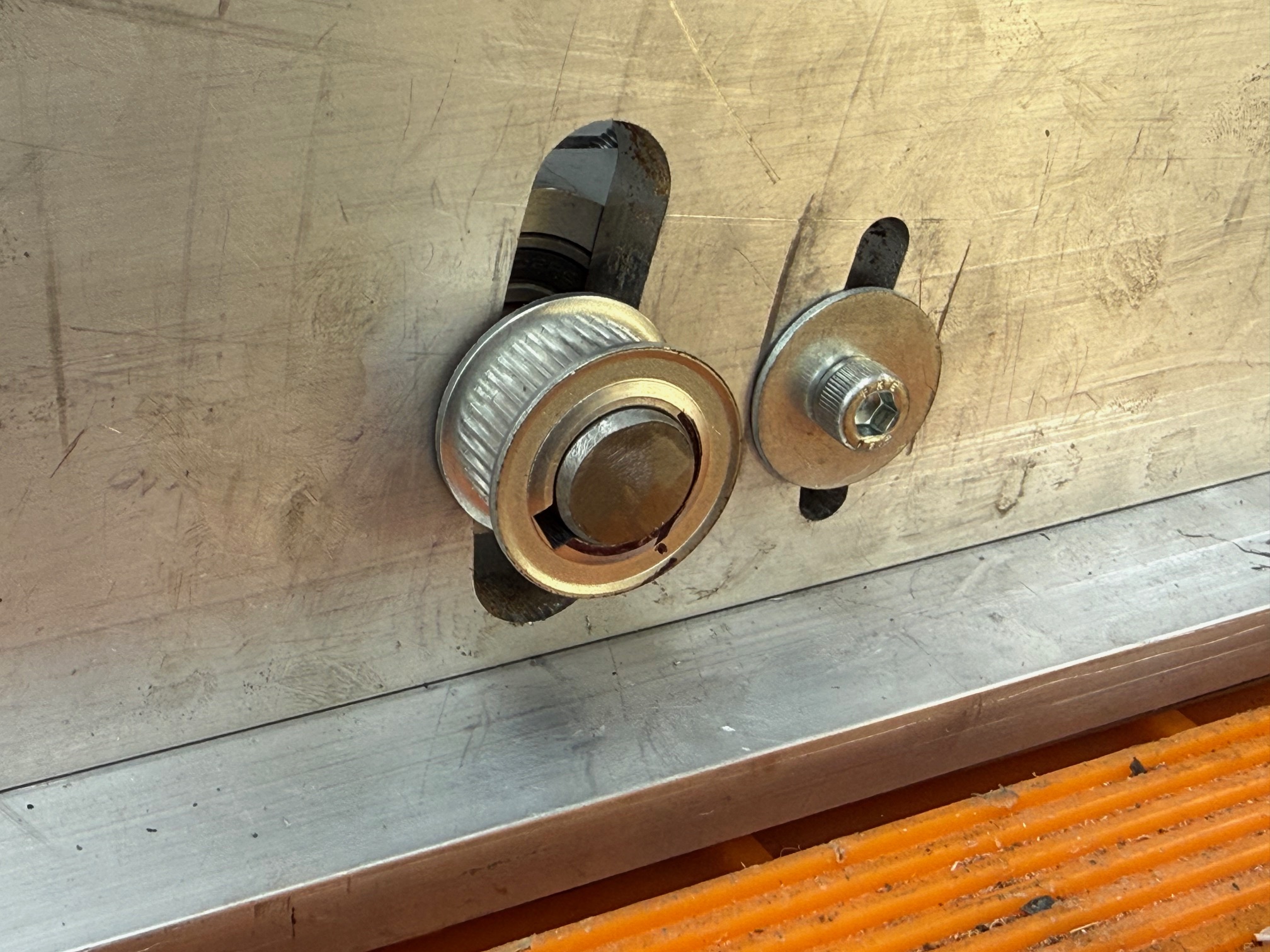
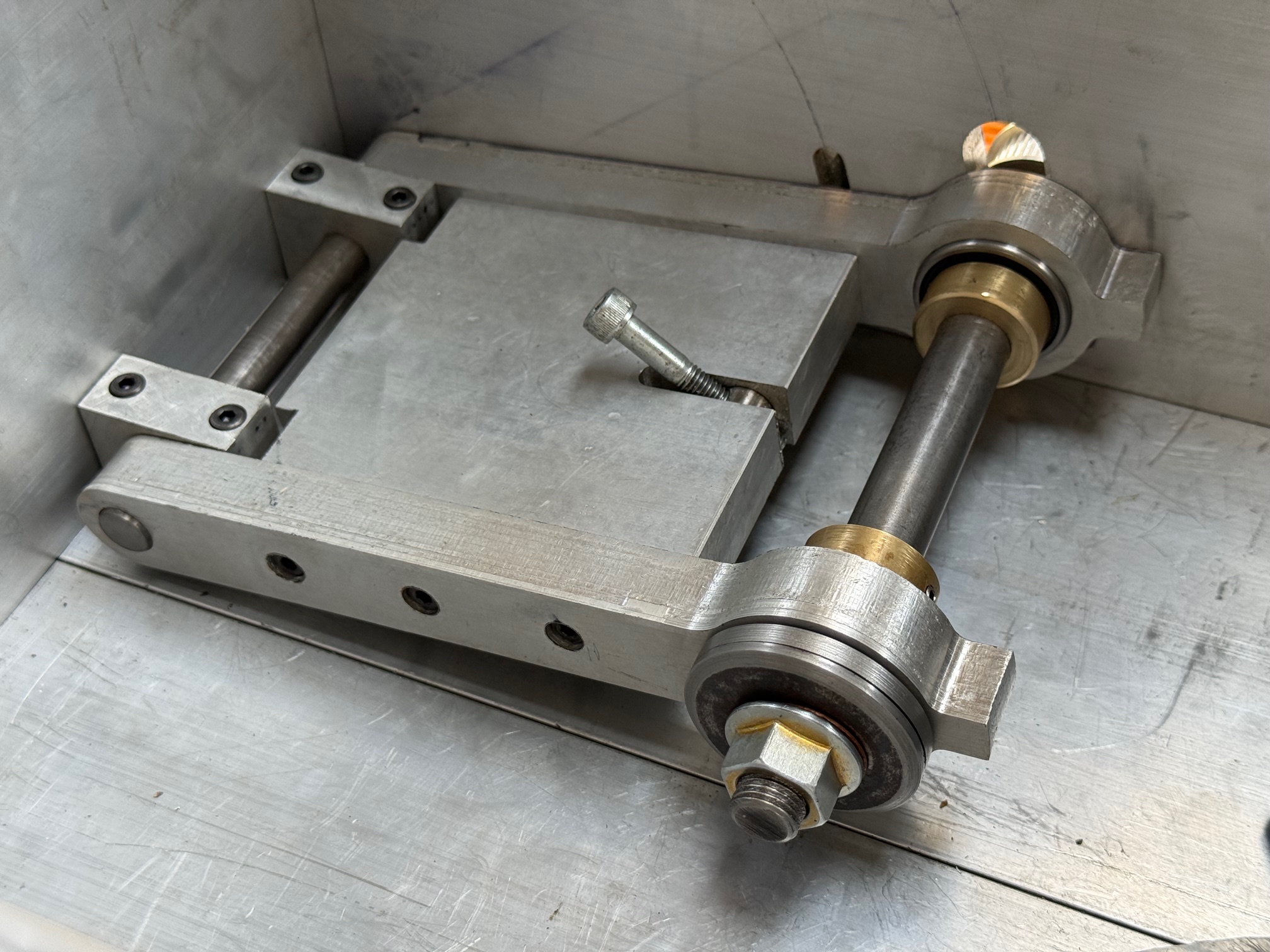
The box and top were made from 12mm thick aluminium, bolted together with 6mm hex socket cap screws. Considerable care was taken to ensure accurate dimensions and squareness. Multiple assemblies and disassemblies were required. The short grooves cut into the front and rear panels were to facilitate bolting to the mill table.The pivoting main shaft support is solid, rigid, strong.Making the main shaft from 15mm steel. The end was turned down to 12mm and a 1.25mm pitch thread cut on the lathe. Then a backing plate was made with a 15mm hole, and silver soldered to the shaft. After it cooled the backing plate was finished with the shaft in the lathe.The case had curved slots milled on my CNC mill, after careful releated measurements of the position, size and shape. Quite a few hours to complete this step.The installed main shaft, ready for a blade and an adjusting mechanism for height. The bearings are pressed into the arms. The brass collars prevent lateral movement.
Still waiting for the motor to arrive from China. I thought that it was Australian stock.
Meanwhile I have assembled the hull keel and bulkheads for Bellerophon, ready for some glue. Keep watching and liking!
I looked but couldn’t seem to re-find the YT video short I watched a few months ago. So I’ll try to explain it. The most clever set up I’ve seen so far for thin strip ripping on a table saw uses just a shop made two piece split fence somewhat like a router table might. The one in the video was made from hard wood, but aluminum would be even better and more durable.
Setting it up and dead square to the blade for your precise strip width would take a bit of time. But that’s what dial indicators are for. 🙂
Basically the fences first section is fixed down and set for the blade to cut the strips thickness, and exactly parallel to the blade. But it’s only as long and up to where the saw teeth just start cutting. The second fence is set with a gap between it and the end of the first fence. And has its end cut at a sharp angle. 10 – maybe 15 degrees I’d guess. The point of that angled cut is set to just catch inside the saw kerf an inch or so after the blade. In use the strip being cut off just catches that leading angled point on that second length of fence, and that instantly steers the strip being ripped off to the right and away from the blade. There’s no risk of kick back with the strip being pinched between the fence and the blade. And your first fence continues to be the gauge for each plank strip being cut.
Thin strips like you want for model ship building are obviously very flexible, so setting it up with that pointed end on the second fence and using it to steer the strip away from the blade as it’s cut worked amazingly well in that video I watched. It goes just as fast as the wood can be run through the saw for each cut. I just wish I’d thought of it first.
I’ll look some more, if I do happen to find that video, I’ll post the link here.
That is a very interesting idea! I will think on it and see if I can incorporate such a system into my saw.
Basically it seems that the angled splitter is directing the thin plank away from the trailing circular saw teeth.
I could use a similar system on my band saw for cutting plank material, but yes, I would like to do something similar on the small circular saw which I am currently building.
Thankyou very much for the idea and description. John.


I looked but couldn’t seem to re-find the YT video short I watched a few months ago. So I’ll try to explain it. The most clever set up I’ve seen so far for thin strip ripping on a table saw uses just a shop made two piece split fence somewhat like a router table might. The one in the video was made from hard wood, but aluminum would be even better and more durable.
Setting it up and dead square to the blade for your precise strip width would take a bit of time. But that’s what dial indicators are for. 🙂
Basically the fences first section is fixed down and set for the blade to cut the strips thickness, and exactly parallel to the blade. But it’s only as long and up to where the saw teeth just start cutting. The second fence is set with a gap between it and the end of the first fence. And has its end cut at a sharp angle. 10 – maybe 15 degrees I’d guess. The point of that angled cut is set to just catch inside the saw kerf an inch or so after the blade. In use the strip being cut off just catches that leading angled point on that second length of fence, and that instantly steers the strip being ripped off to the right and away from the blade. There’s no risk of kick back with the strip being pinched between the fence and the blade. And your first fence continues to be the gauge for each plank strip being cut.
Thin strips like you want for model ship building are obviously very flexible, so setting it up with that pointed end on the second fence and using it to steer the strip away from the blade as it’s cut worked amazingly well in that video I watched. It goes just as fast as the wood can be run through the saw for each cut. I just wish I’d thought of it first.
I’ll look some more, if I do happen to find that video, I’ll post the link here.
LikeLike
That is a very interesting idea! I will think on it and see if I can incorporate such a system into my saw.
Basically it seems that the angled splitter is directing the thin plank away from the trailing circular saw teeth.
I could use a similar system on my band saw for cutting plank material, but yes, I would like to do something similar on the small circular saw which I am currently building.
Thankyou very much for the idea and description. John.
LikeLike