machines which I have made, am making, or intend to make, and some other stuff. If you find this site interesting, please leave a comment. I read every comment and respond to most. n.b. There is a list of my first 800 posts in my post of 17 June 2021, titled "800 Posts"
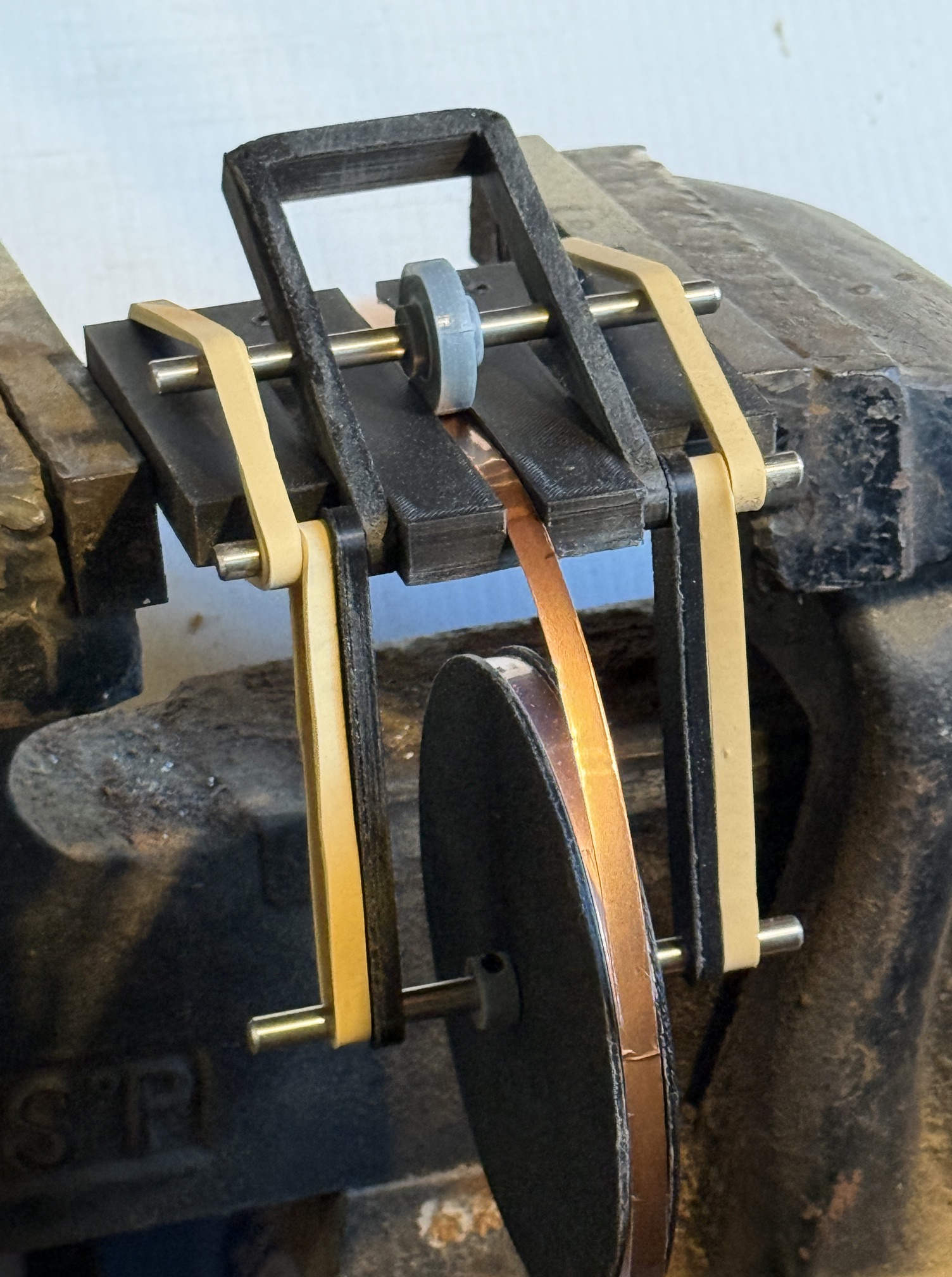
I took my prototype impressioning machine to my Model and Experimental Engineering Society today, and so I could demonstrate it, added some collars (as in the previous drawings) and some rubber bands to increase the pressure on the impression wheel.
Like this, except with collars on all of the shafts.
The rubber bands on the impresion wheel shaft worked so well that I will not bother with installing metal springs.
I am continuing to experiment with different heights and diameters of the nail head and plate divider impressions, and some other mechanical aspects.
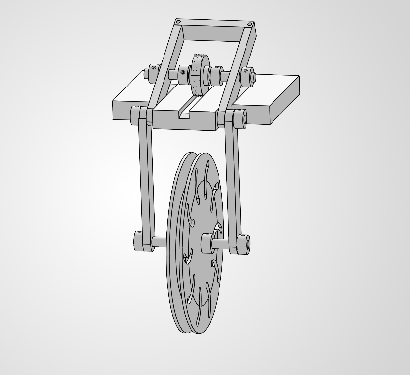
A progress report on my copper tape embossing jig for making impressions in adhesive backed copper tape for simulating model scale copper plates and nail heads.
There will probably be some further refinements to the jig, but it has been made (3D printed) to this design and is currently functioning.
The horizontal base is clamped to a table or bench top, or held in a vice. The reel of copper tape is held in the large wheel and the tape is fed under the smaller “impression” wheel. The gantry holding the impression wheel is held against the tape under pressure with thick rubber bands .
The tape is then pulled through at a moderate and steady rate, causing the impressions to be made.
The plates could be cut individually, or left in hull length strips, and applied to the hull.
This method is quite effective, but has one drawback….
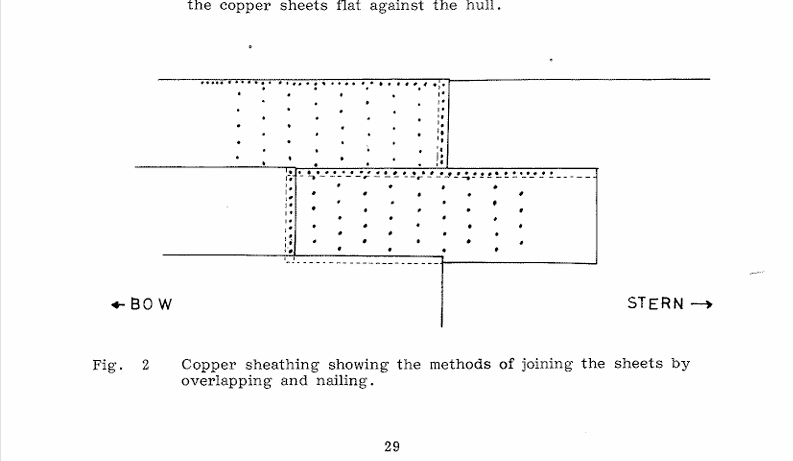
Since the rows of plates in British warships of the Napoleonic era were installed from the keel upwards, and the bottom plates overlapped the top ones, the top row of nails in the bottom plates must have been hammered in AFTER the top plates were sitting or held in place. I suggest that the top plates sat on the second top row of nails of the bottom row plates while the top row of nail holes were punched through both bottom and top plates,
and the nails then inserted and hammered in.
I hope that my explanation is understandable.
I have no contemporary references for the procedure but that is the only way that I can see that it could have been done. And that procedure is not feasible with adhesive backed copper tape.
If any readers have an alternative explanation for the procedure I would be very happy to hear it.
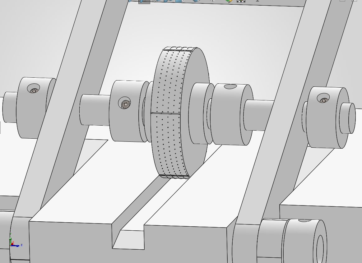
Incidentally, the nail head pattern which is visible in this picture has later been updated, made more accurate, by doubling the number of nails around the periphery, which is consistent with patterns from the era.
I encountered some difficulty holding the hull planks in position for gluing them to the prow. Well actually there are numerous difficulties holding the springy curved planks against the hull in many positions, but this post is just about the join between planks and the prow.
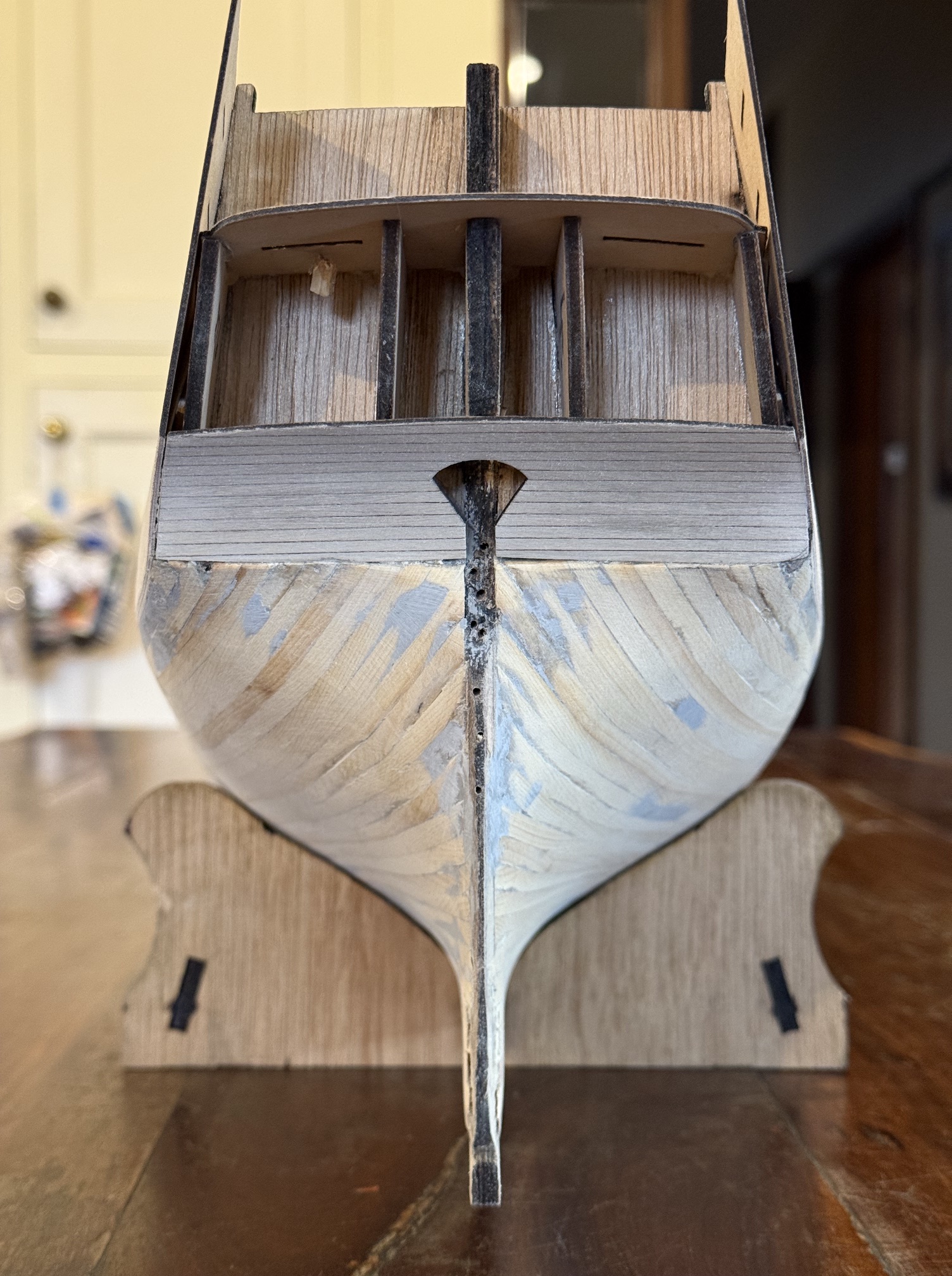
The prow on my model is a piece of 6mm thick marine ply which joins to the keel. It provides a handy and strong clamping point.
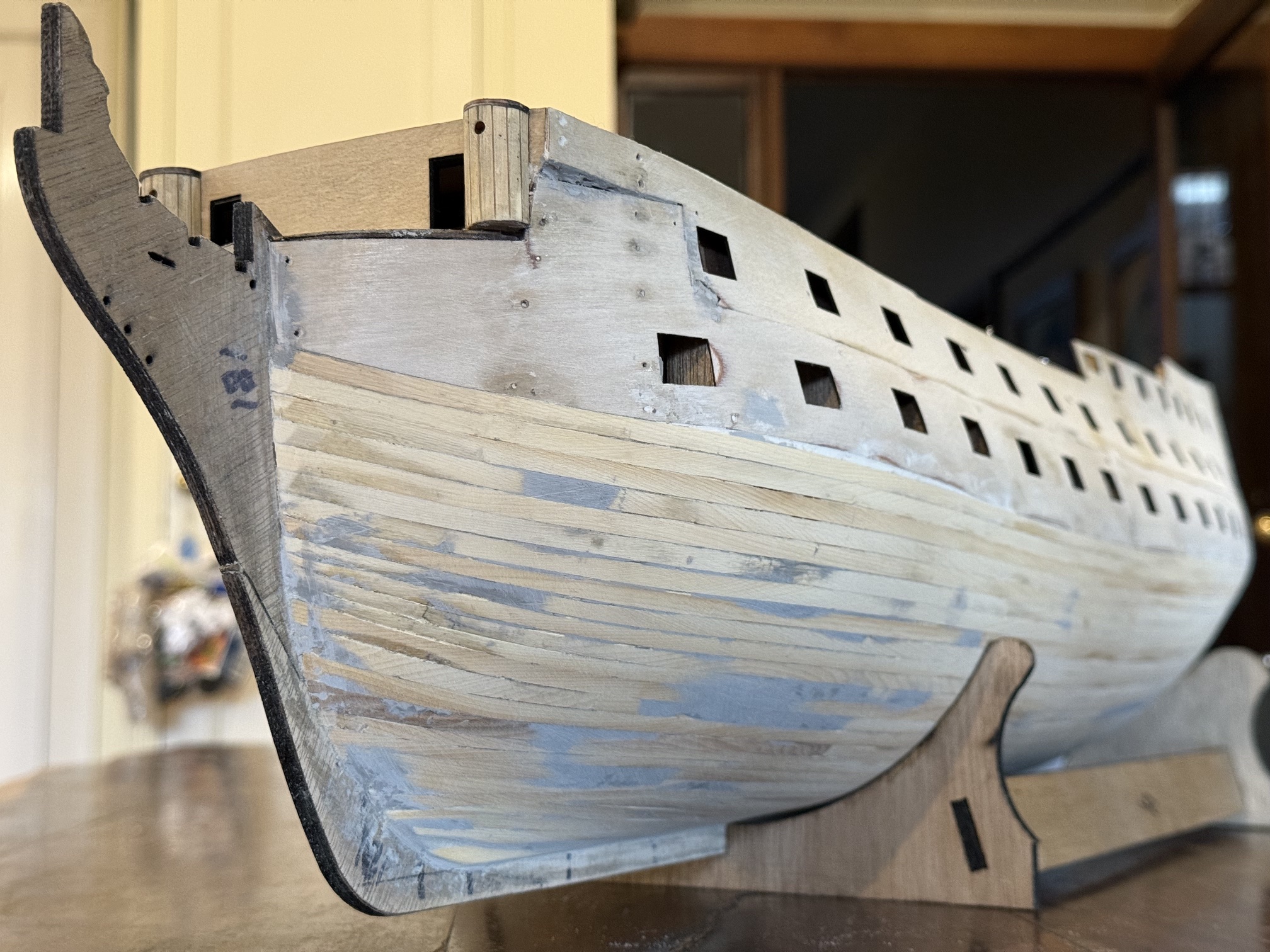
The prow is the bit labelled “181”. The planks in the photo are the first layer, and they have been filled and sanded to nicely smoothed and curved surfaces, to provide a good base for the surface planks of the second layer. The second layer of planking remains very visible so filling is to be avoided and sanding is kept to a minimum because the second layer planks are only 1mm thick. For the same reason, any clamping method should not dent the second layer planks, and joins should be accurate and tight. To hold the planks in position during gluing the middle sections can be held down with rubber bands, but the extreme bow and stern sections need some forethought.
The second planking layer also covers the plywood which forms the gunports. At the prow the plywood forms almost a 90 degree join with the prow. Lower down the planks form an increasingly obtuse angle with the prow.
Also, the planks need to be matched on the port and starboard sides, plank for plank.
…..like these first layer planks ending on the rudder post, but without the fill and with neater joins.
So back to the SolidWorks drawing board, and this is what I came up with…
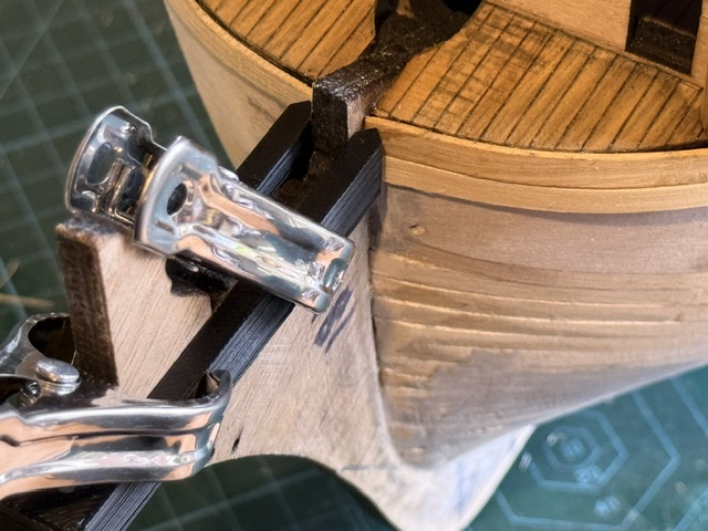
The slot is the same width as the prow thickness… in this case 6mm. The length of the slot is 65mm which just clears the prow. The pointy bits are to apply pressure to the plank to hold it against the hull. Points rather than flat surfaces to minimise adhesion between the clamp and the plank in case there is contamination with glue.
The vertical distance is 10mm which will cover one plank above plus the plank which is being glued.
In this photo the top plank has been glued in position, and the lower one is clamped in position, ready for gluing. The planking clamp is held in position with one or two spring clamps. I did consider making provision for a bolt and wingnut fastener but the spring clamps seem quite adequate. The tool can remain in position for the other side to be correctly lined up.
Another option would be to cut a rebate in the prow for the planks to fit into. I am unsure whether I am too lazy for this, or whether I was not confident of doing a neat enough rebate. In any case I decided that a good clamped glue join would have to be adequate. Or, glue onto the side faces of the prow a veneer of timber (in the correct orientation in my case!) which will hold the plank ends in position. I may well do this anyway, as belt and braces, in case the glue ever weakens.
If anyone wants to copy the design please feel welcome, (I can post an stl file for 3D printers if requested) but note that the slot width and length will depend on the exact prow dimensions of your model ship.