
Bellerophon 2nd Planking (cont) A New Tool.
by John
I encountered some difficulty holding the hull planks in position for gluing them to the prow. Well actually there are numerous difficulties holding the springy curved planks against the hull in many positions, but this post is just about the join between planks and the prow.
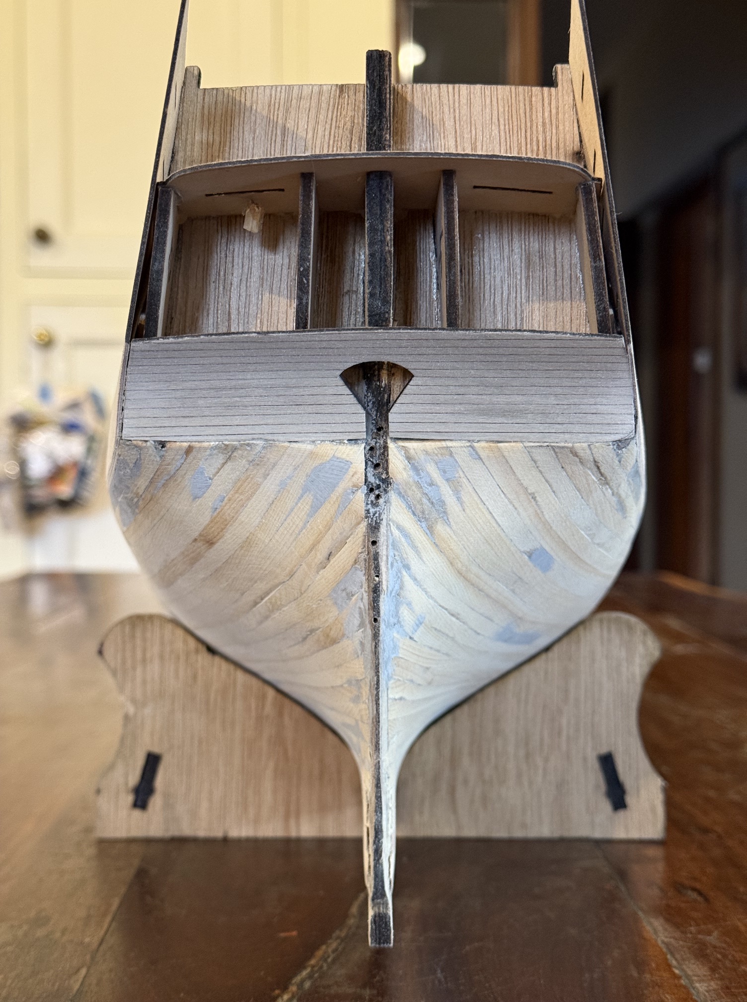
The prow on my model is a piece of 6mm thick marine ply which joins to the keel. It provides a handy and strong clamping point.
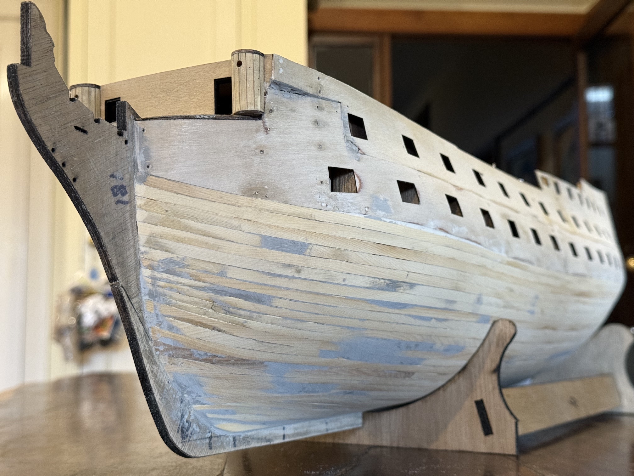
The second planking layer also covers the plywood which forms the gunports. At the prow the plywood forms almost a 90 degree join with the prow. Lower down the planks form an increasingly obtuse angle with the prow.
Also, the planks need to be matched on the port and starboard sides, plank for plank.
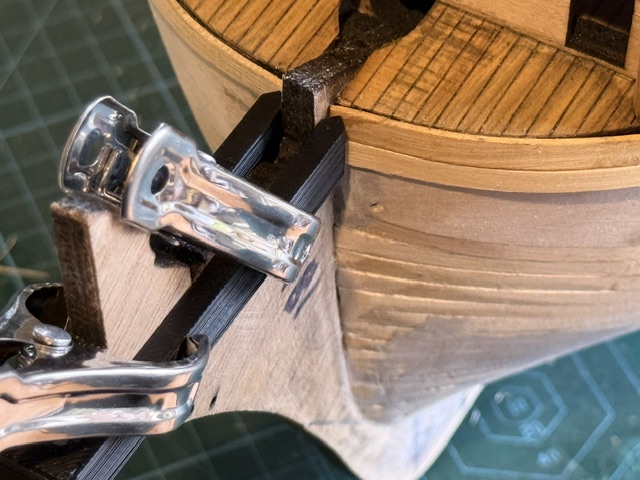
So back to the SolidWorks drawing board, and this is what I came up with…

The slot is the same width as the prow thickness… in this case 6mm. The length of the slot is 65mm which just clears the prow. The pointy bits are to apply pressure to the plank to hold it against the hull. Points rather than flat surfaces to minimise adhesion between the clamp and the plank in case there is contamination with glue.
The vertical distance is 10mm which will cover one plank above plus the plank which is being glued.
Another option would be to cut a rebate in the prow for the planks to fit into. I am unsure whether I am too lazy for this, or whether I was not confident of doing a neat enough rebate. In any case I decided that a good clamped glue join would have to be adequate.
Or, glue onto the side faces of the prow a veneer of timber (in the correct orientation in my case!) which will hold the plank ends in position. I may well do this anyway, as belt and braces, in case the glue ever weakens.
If anyone wants to copy the design please feel welcome, (I can post an stl file for 3D printers if requested) but note that the slot width and length will depend on the exact prow dimensions of your model ship.
