johnsmachines

machines which I have made, am making, or intend to make, and some other stuff. If you find this site interesting, please leave a comment. I read every comment and respond to most. n.b. There is a list of my first 800 posts in my post of 17 June 2021, titled "800 Posts"

Tag: 3d printer

3D Printing a Cannon Barrel

There is quite a learning curve to 3D printing, and most of my prints so far have exhibited considerable room for improvement.  There are some helpful YouTube videos on the subject, but at my beginners level there is still a lot of trial and error.

I am still planning my next cannon model build, and printed some cannon barrels to improve my printing skills, and also to have a plastic model of the barrel to help decide about construction methods of the metal model.

P1053560

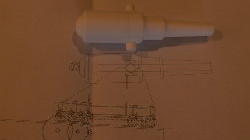
This is a 1:20 print, but was unsatisfactory because the cascable, and the rifling did not print.

The next prints took 22 hours (vertical orientation) and 24 hours (horizontal orientation) each.

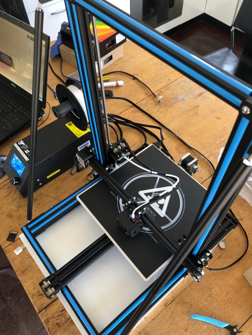
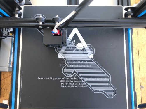
Firstly the vertical orientation..

P1053570

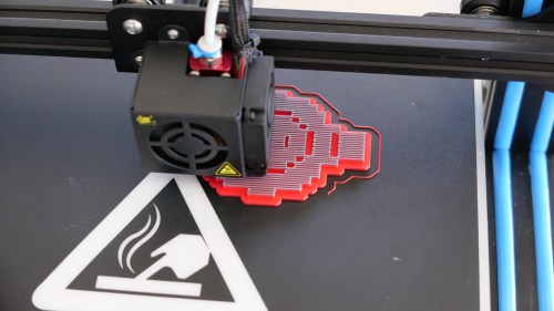
It starts with a thin line which marks a little beyond the outside outline of the model to ensure that it is properly located on the printing plate.  Then a thin base to ensure adherence of the model to the printing plate, for the duration of the printing.  My plate is heated to 60ºc, which is not essential with the PLA filament which I am using.  I changed the filament colour for aesthetic reasons.

P1053571

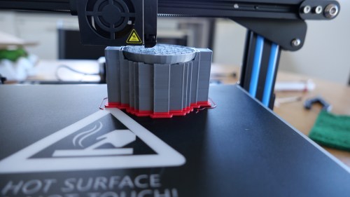
Each layer of filament adds another 0.2mm of height.  The rectangular columns support the overhanging parts, and increase the overall support of the model during printing.

P1053574

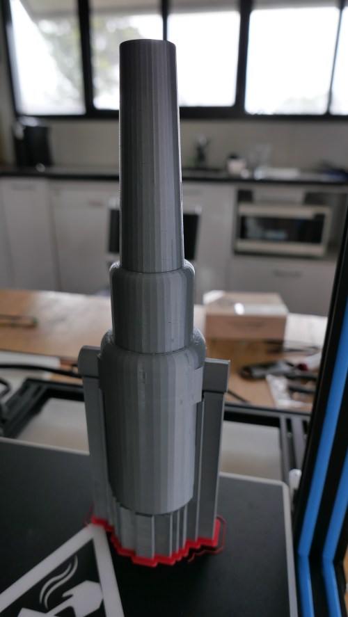
The printing is finished after 22 hours.  I can already see some mistakes.  The barrel should be smoothly rounded, instead of faceted.

P1053584

After breaking off the supports.  Next to a bit of workshop rod  which I will use to make the actual cannon model.   Not quite long enough, but the rifled gun tube and cascabel will be made separately so the steel rod will be long enough for the rest of the cannon.

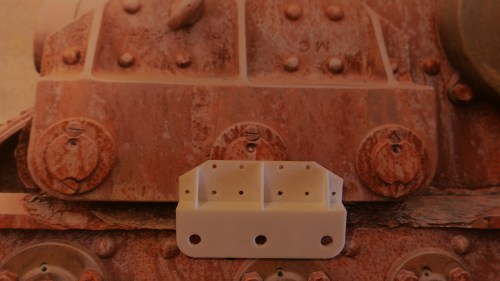
The next print was horizontal…

IMG_8505

IMG_8507

I made the supports more densely placed to improve the support.  The cannon barrel is just appearing in the centre.

IMG_8509 2

I left the printer to continue overnight, and this is what I saw next morning.  Note the longitudinal placement of the plastic fibres.  Infill set at only 3%, which was adequate.  I increased the outside wall thickness to 5 layers, which was plenty thick enough.

IMG_8511

P1053590

The finished horizontal print on its supports (front) and the vertical version (behind).   Apart from the facets, the appearance of the vertical version was better IMO.

Now I am ready to turn the barrel in steel.  I have obtained a facsimile book about naval artillery which was written in the late 19th century, it reveals that the Armstrong barrels were made in concentric pieces, and heat shrunk together.  I will adopt a similar method, making the cascabel and the central rifled tube separately from the breech sections.   Not decided whether to heat shrink them together, or silver solder, or Loctite. (ps. a week later.  Changed my mind.  Making the barrel from a single piece of steel)

The artillery book also answered my question about 64 -80 lb cannon and bore sizes.  When round shot was replaced by pointy cylindrical projectiles, the projectile weight could increase by increasing the length rather than the diameter of the projectile.  And some 64lb cannons were redesignated as 80 lb cannons, after modifications which did not necessarily alter the bore.  Unfortunately the book does not answer how the rifling was accomplished with a closed breech.

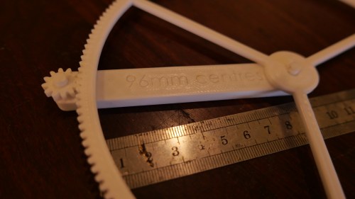
And I made another workshop tool.   This one is a lathe tool height gauge.

P1053566

I expect that the tough PLA will stand up to workshop treatment quite well.  It is light, very visible, will test upright and upside down tool bits, and will hang on a conveniently placed hook. Also, it is within 0.01mm of the required 38.05mm tool height.  A light rub of the base over fine emery paper will get the dimension right on.


3D Printing is FUN! (but still slow)

IMG_8498

My 3D printer.  Bought from Amazon on a special offer.  $AUD279.  Worked straight out of the box after minimal assembly, and using the supplied plastic filament (PLA).  You can see the large gear on the platten which I drew up using a CAD program.  I used the software (Cura) supplied by the printer manufacturer (Creality).   The printer is a Creality CR -10S.  The “S” refers to a “filament out” sensor which I have not yet installed.  I read some reviews of the printer before spending my money, and so far I am very happy with it.  You might notice some bracing bars which I bought separately on Ebay.  Not sure if they are necessary, but they might improve the print quality by reducing vibration in the printer.

P1053563

These gears and shafts were printed.  They were used to check the sizes of parts for my next model cannon build.  I used a program called “Gearotic” to plan the gear module, teeth numbers, distance between centres etc.  Gearotic is also great fun.

P1053561

The printed gear and pinion quadrant on a background of a photo of the real cannon.  On my model the gear and pinion will be made of steel or brass, machined from bar stock.

P1053558

Another part sitting on a photo of the original.  This demonstrated that I had got the corner chamfer a bit wrong.  Much better to discover the fault at this stage! 

P1053560

A half size print of the barrel.  This was just for fun.  The final part will be ~300mm long, and will be machined from steel.  This print took almost 4 hours.

P1053557

A print of the centre column which the cannon chassis sits on and traverses around.  It is ~60mm tall.  It will be tricky to machine from solid bar.  Could be fabricated in pieces and silver soldered together, but I am considering using the printed part to make a mould and cast the part in brass or bronze……   The original cannon column has an 5-600mm extension into the concrete base which my model will not need.

So far all of these prints have been made from PLA filament, which I read is easy to use, tough, rather brittle, and has a low melting point.  It is also inexpensive (about $20-25 for 1 kg).  I am still on the supplied small roll which came with the printer.  Future prints will be in colour!

The weather is a bit cooler today, so I might get back into the workshop and make some metal swarf.


3D Printing is SLOW

P1053454.JPG

Crealty CR-10s 3D printer.  The machinists parallels were my solution to ensuring that the horizontal arm is parallel to the base frame.

So, I took delivery of the 14kg box, and spent a couple of hours assembling the printer.  It was partly assembled, as delivered, and if I had known what I was doing the final assembly would have been done in a fraction of the time.  The assembly instructions were adequate.  The wiring connections were well labelled.  The wiring connectors were delicate, and I took care not to bend or break them.

The vertical frame bolts to the base frame, and it is surprisingly rigid.  There are 2 Z axis stepper motors, and when not powered up, they can be individually turned.  It occurred to me that the horizontal arm which the Z axis motors raise and lower should be exactly parallel to the base, so I placed the machinist’s parallels as shown in the above photo and screwed the horizontal arm down onto the parallels to set the horizontal position.  I assume that the Z steppers will move the arm equally. (Hmm… I will check that assumption later.)

Next day, I downloaded the operating software.  An older version was supplied with the machine, and the newer version would not work on my old XP Pro Windows computer, so I used the old version.

I spent some time manually levelling the bed, then ran the automatic bed levelling software.

The printed operating instructions are very basic.  An Internet connection is assumed, and I did not have one available, so my first printed object was with default settings and the supplied white filament.

Somewhat to my surprise, it worked.

P1053455.JPG

The platten is aluminium.  A glass plate was also supplied, so I used that on top of the aluminium.

The filename was “dog”.  I had no idea whether “dog” was a 3D dog, a picture, or whatever.  Neither did I have any idea of its size.  After an hour, I had printed a disk about 125mm diameter and 1.1mm thick.  Then the disk came off the platten, so I aborted the print.

Today, after getting some advice from Stuart T regarding print adhesion I removed the glass platten cover and applied some special adhesive 3D printer cover.  It is called “3M double coated tissue tape 9080A”.  Then I printed 2 more items.  Neither broke free.  in fact they were difficult to remove at the conclusion of the prints.

P1053466.JPG

This tiny Tyranosaurus was printed from a 3D file which I found on my computer.  It printed in about 20 minutes.  Default settings again.  The supports were too big for the object, and when I broke them free I also broke off the T Rex arms.  Some settings for supports need to be changed.

The next print was a tool which I planned for the 3D printer…..

P1053468.JPG

The item is a speed handle for a milling vise.  It is 80mm diameter with some grippy indentations on the circumference.  The tricky feature to make is the hex hole, to fit a 19mm hex shaft.  This is the 3D drawing, imported into the Creality software, so the G code can be generated.

P1053469.JPG

First layers.  Each layer is 0.2mm thick

P1053475.JPG

The internal framework is a bit lighter than I wanted.  I thought that I had chosen 90% density.  (ps.  a couple of weeks later.  The speed handle seems to be standing up to the usual rough treatment in my workshop, despite my misgivings about its lightness.)


P1053477.JPG

The speed handle on the vise.  Nice fit.  The print took over 2 hours.

Error
This video doesn’t exist

Not perfect, but too bad at all.


Cylinder valves for triple, and a neat method for cutting thin grooves.

The triple expansion steam engine now has a valve in each cylinder head.  They are manually controlled, not automatic, and I guess that is the reason they are called “false” valves.

The body of each valve was shaped in the CNC lathe, using software called “Ezilathe”.   There is a lot of good software for CNC milling machines, particularly Mach 3, but not much for lathes, at least for the non professional user.  “Ezilathe” is a free program (currently), works brilliantly, and was written by my friend Stuart.  It has an inbuilt simple CAD program, automatically generates G codes, and has a G code editor.   It also has a terrific, easy to use threading facility. It has an accurate simulator, and a tool editor.   Do a search on CNC Zone to download a copy.

The

The “false valves” in the cylinder heads.

One problem which I experienced with these valves was that the thread which secures the valves to the heads, stopped short of the expanded hexagon part by about 1mm, and I needed to turn a very narrow groove in the stem to allow the hexagon to screw down hard on the head.  I do not have a lathe narrow grooving tool with enough reach to do this, so the following photo shows how it was done…

A broken slitting blade, held in a shop made holder.  Normally I use it under power, but in this case, the part was held fairly tenuously, so I turned the lathe spindle by hand.  It worked perfectly!

A broken slitting blade, held in a shop made holder. Normally I use it under power, but in this case, the part was held fairly tenuously, so I turned the lathe spindle by hand. It worked perfectly!

Just for interest. This tiny engine was made by model engineer Peter B on a 3D printer.  It is about the size of a matchbox.

Just for interest.
This tiny engine was made by model engineer Peter B on a 3D printer. It is about the size of a matchbox.