johnsmachines

machines which I have made, am making, or intend to make, and some other stuff. If you find this site interesting, please leave a comment. I read every comment and respond to most. n.b. There is a list of my first 800 posts in my post of 17 June 2021, titled "800 Posts"

Tag: 6″ vertical boiler

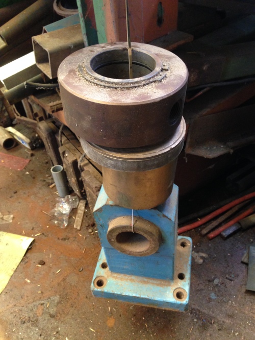
A steam driven water pump, and a whistle.

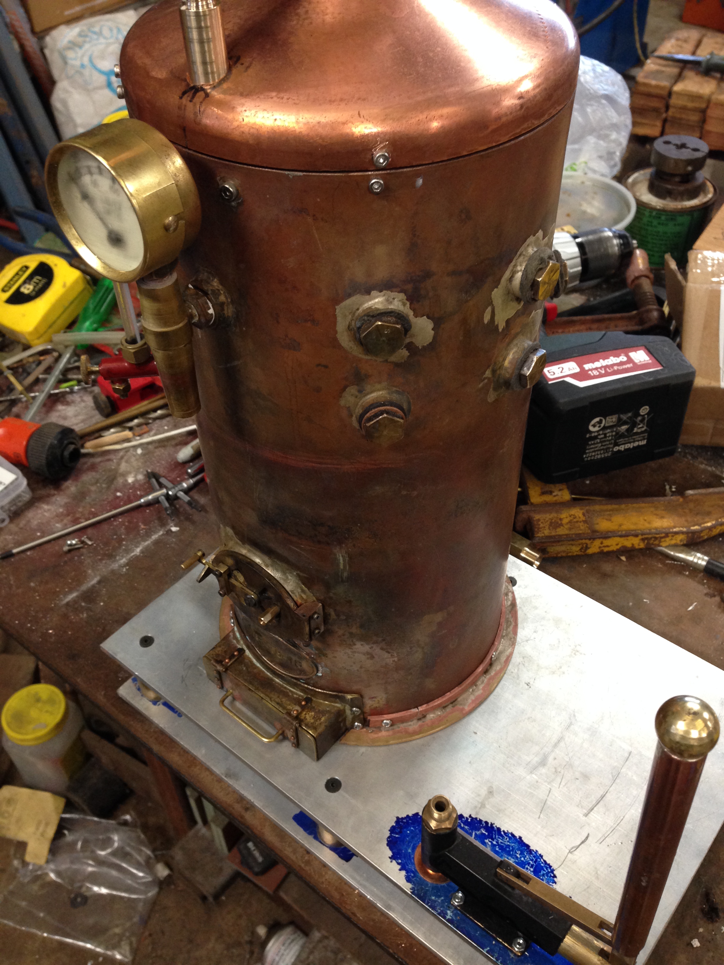
Boilers, whether full size or model, get through substantial volumes of water.  When my 6″ vertical boiler is working hard, so is the water pump, to replenish the water which is turned to steam.

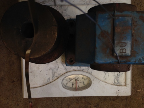
At present, the water pump is a manual pump, and it needs to be operated almost continually when the boiler is steaming hard.

IMG_6791

I am not sure whether operating the hand pump (lower right), or the propane burner, consumes more energy.

So it was with great interest that I viewed the steam pump in operation which was built by Stuart Tankard, at last night’s meeting of GSMEE.  I have plans and castings for the same unit, and expect to make it later this year.  It is a Worthington type pump, and the castings and plans were supplied by Southworth Engines.
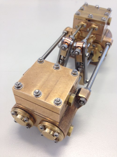
IMG_6664

Stuart’s latest.


In this video, for the demonstration, the pump is running on very low pressure compressed air.  The larger cylinders are the steam powered driving cylinders, and the smaller ones are the water pumps.  So whatever the pressure of the steam, the water pressure will be greater, and able to be pumped into the boiler.

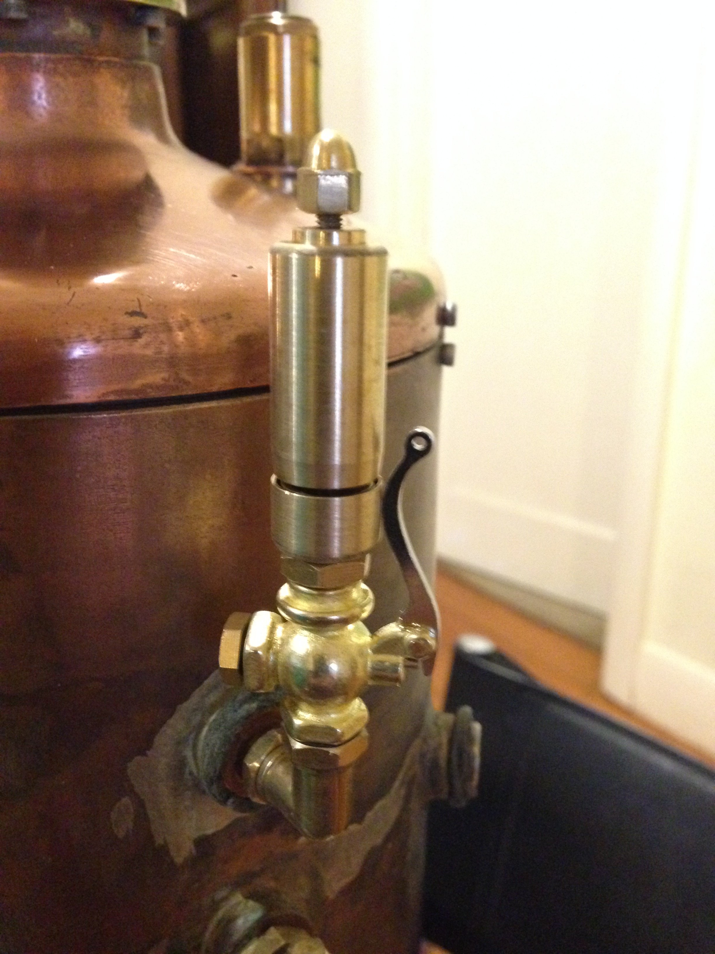
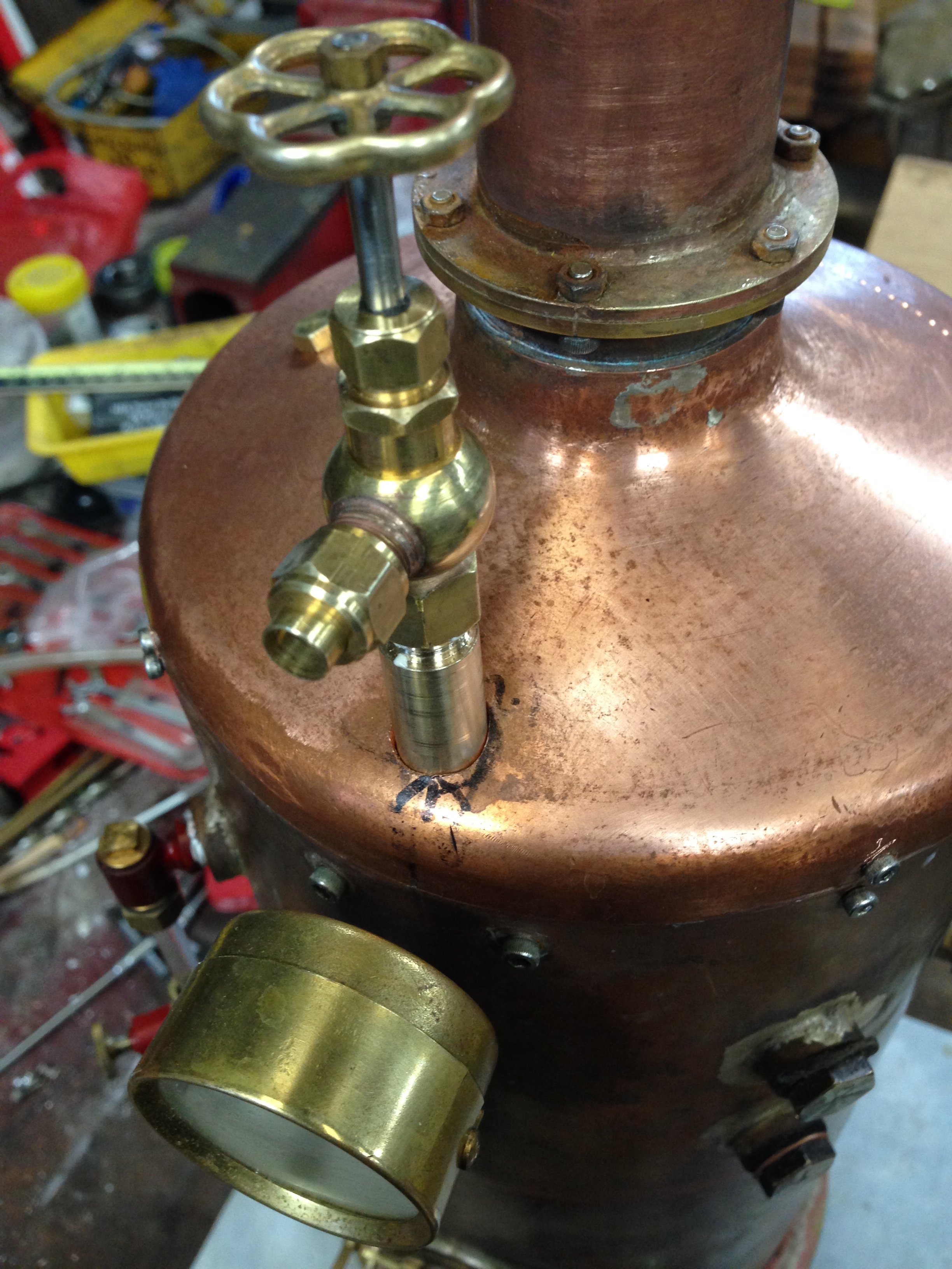
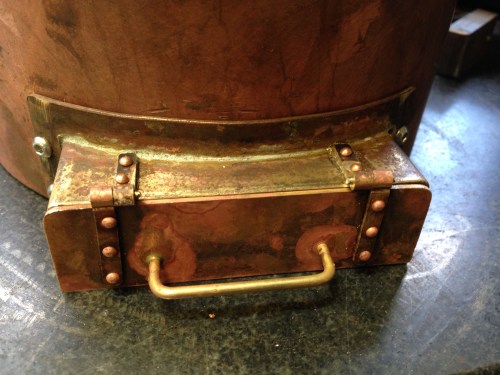
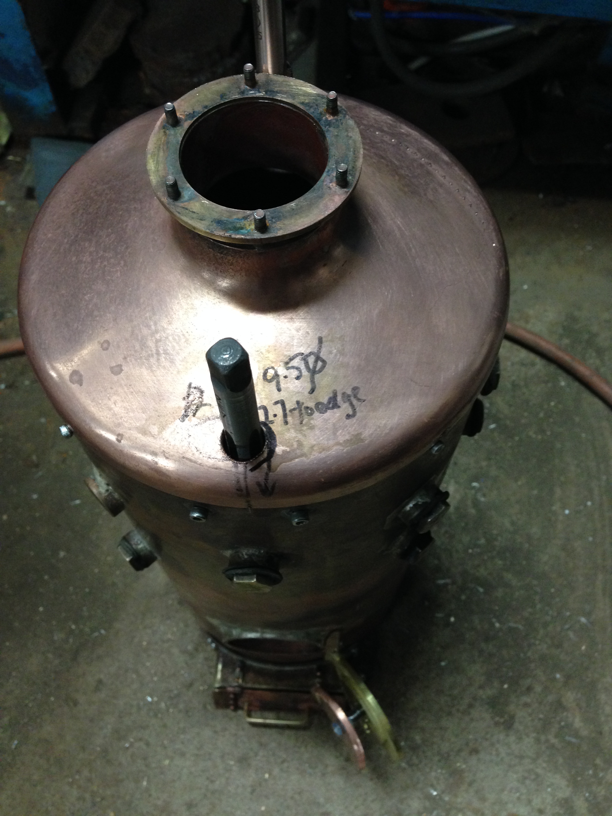
And finally, I bought a steam whistle.  It was supplied by Microcosm.engine from China and it was very reasonably priced. ($US39).  I have not tested it yet, but it came highly recommended by Keith Appleton.  It is certainly very nicely made.  I screwed it onto the boiler as a bit of bling because I showed my boiler progress at last night’s meeting of GSMEE.

IMG_6790.JPG

Almost ready for the boiler inspector.

Almost ready for the boiler inspector!

It feels like the countdown to the finals medical exams!

So today, I drilled the gas jet from 0.22mm to 0.3mm.   A drill bit to drill 0.3mm, is, at least to my eyes, barely visible.  It is finer than the finest sewing needle.  If I pick up a 0.3mm drill bit I can not feel it.  It has no discernable weight.

So this is how I increased the jet size from 0.22 to 0.3mm.

Oops!  I forgot to take a photo.  I bought a set of micro drills from Jaycar, and the smallest bit was 0.3mm.  So I mounted it in the Dremel, and ran it at 10,000 rpm.   for a vise I used my fingers.  The drill went straight through the millimeter or so of brass with no detectable resistance.   Managed to miss my fingers.

0.22mm to 0.3mm diameter is almost a doubling in area of the jet orifice, so I tested the flame.  It was (not surprisingly) much bigger!   And still a good blue colour, with minimal yellow.  So I stopped there.   I also installed an adjustable propane regulator Huib.

Then I made an angle piece to secure the boiler to its baseplate.

IMG_6783.JPG

I needed a non rusting disk, 165mm diameter, with a 152mm hole.  The disk was 2mm thick.  So I roughly bandsawed it out in 2mm brass sheet, then set it up in the lathe as shown above.  Turned the outside diameter.  The brass sheet is held just with pressure between the headstock and the tailstock, and the disks of wood.

IMG_6784.JPG

Then I held the disk in the 3 jaw chuck and used a parting tool to cut out a disk to form the middle.  The waste middle came out with a bang.  I was careful to stand to the side, anticipating the decapitating scythe.   And I was not disappointed.  I did have to check that my head was still attached.

IMG_6785.JPG

Again, I was so involved with the machining that I forgot to take pics.  The vertical part of the angle piece is a slice of copper tube which I had reserved.  It was silver soldered to the brass  disk, then screwed to the boiler wrapper.   Some further fitting, and it ended up like this.

IMG_6786.JPG

The hand pump has been mounted.  yet to be connected.  A steam driven water pump will eventually occupy the spare space.  And just to make quite sure that there is enough water pumping capacity I will also be installing an injector.

IMG_6787.JPG

And another nice bit of bling (John).  This globe valve was made by Stuart Tankard.  I have borrowed it, pending me making one of my own.

Just how strong is a silver soldered join?

I bought some 6mm x 0.7mm brass strip to hold on wooden lagging on my 6″ vertical boiler.   Trouble was that I could find suppliers who had the strips only in 300mm (12″) lengths.  So I decided to join 2 of the strips to provide the 450mm lengths that I need.

I have made band saw blades with silver solder, quite succesfully, but the ends were scarfed so the join was over a 5mm or so length of the blade.

I wondered whether I could butt join the brass strips with silver solder, and if so, whether the join would be adequately strong.

IMG_6744.JPG

So here are the brass strips end to end, fluxed and weighed down so they do not move.

IMG_6745.JPG

And here is the silver soldered join.  Not particularly neat, but OK for the purposes of the test.

IMG_6746.JPG

The other side.  As I said, not particularly neat. And I did not even bother with an acid soak.

IMG_6747.JPG

So I drilled a hole in the end of the joined strips, and wired on a hefty weight.  The top end was held in the vise.   Seemed OK so I increased the weights.

IMG_6748

IMG_6749

Looking down the strip from the vise.

IMG_6750

IMG_6752

By this stage I was standing back, expecting the soldered join to give way.  But it did not.  Hmm.   Must do a tidy up soon.


IMG_6753

21 kg, 46.3lbs.

At this point I stopped adding weights.  I think that the soldered join should hold the wooden strips to my model boiler!

Are you impressed?  I am.


A new skill- riveting stuff

And I don’t mean pop riveting.  I used some solid copper rivets on the vertical boiler today.  I tried to avoid them, hoping to use small bolts and nuts instead, or even soldering,  but ended up doing it properly and using solid copper rivets.

IMG_6741.JPG

They do look the part.  No?  This is the ash pan door.

The copper rivets are already annealed.  You need an anvil with a depression which is the same same shape and size as the rivet head, a hammer, holes drilled and a method of cutting the rivets to length.

I secured the anvil in the vise.  The anvil was a bit of steel rod into which I bored a hemispherical depression with a ball nose end mill.  I super glued the boiler parts together, then drilled them.

Then hand held the parts containing the rivet, used side cutters to cut the rivet to length so that about one diameter of rivet was protruding, placet the rivet head onto the anvil, then gave the cut end a few taps with the hammer, to pean it over and secure it.  Easy as!

Those are the first solid rivets I have used.   Ever.

Then I silver soldered the handle in place.

The next job was a bit trickier.  I made some holes in the smoke box lid to let the safety valve and dry steam header poke through.  I tried drilling them initially, holding the lid with my hand, but the inevitable happened….   the drill bit grabbed, spun the work around, threw it and left a row of little dents on the copper surface.  I had been contemplating polishing the copper or painting it.   I guess this little accident means that I will be painting it.

So next I held the lid on the wooden form which I had used to make it, and held the form in the drill vise.  No more grabbing and throwing, but it was a bit tense.  I gradually worked up the drill sizes, and when it became close to the desired measurement, I filed the last bits.

IMG_6742.JPG

Those taps are vertical.  They appear to diverge because the iphone has a wide angle lens.  2 penetrations made.  One more to go.

IMG_6743.JPG


Hanging a door on a boiler.

After yesterday’s disaster, I realised that I could not fix the door and vent that I had spent so many hours making.  The vent holes and the vent itself were too big for the opening into the boiler.  So I had to totally redesign and remake them.

But you know what?  When you make something a second time, you have done it before. And the second making is MUCH faster.

So I remade the firebox door and the vent control grill.  Then I made another hinge.  And I attached them to the boiler.  And you know what else….   I broke another f*****g 1.5mm drill bit in the hinge…. again.  But it is OK.   I have made that mistake only twice on this job, so I have got two more goes before I slit my wrists.

As for the suggestion that I use EDM to remove the broken drill piece, I really doubt that would work on a 1.5mm drill.  But maybe…..

But the broken drill bit was in both the door and the hinge.  So I just left it there, and it can become half of the hinge pin, permanently.

IMG_6736.JPG

The top hinge pin is the broken drill bit.  The bottom half is the 2mm cap screw which I managed to thread in place.  The photo is upsidedown.  This is not yet finished.  I still need to make and install a baffle for the door.  And the ugly soldering splodge will disappear under the paint or the wooden slat lagging….  haven’t decided yet. 

IMG_6735.JPG

The door is eliptical.  And it will be painted so I have not fussed too much about finish.  This photo needs to rotate 90º.


Two steps forward one step back again!

I had a whole day to myself, in the workshop.  SWMBO was happy painting or something, and the kids did not need us to baby sit the grandchildren.  So, let’s make the 6″ boiler fire door and ash pan door.

But first, I silver soldered the 4 joins on the super heater, and all went well.

The firehole is oval shaped, and the plans call for a rectangular door.  So I spent some time planning the machining for the rectangular door boxed section.  Then I thought … hang on…. this oval is really nice… why am I hiding it behind a rectangle ?

So back to the computer, and I worked out a method to make an oval door.  A bit like a hobbit door, with an adjustable vent.

IMG_6733.JPG

And here I am, machining it with a 2mm cutter.  In 1mm deep bites.  That brass is 4mm thick.

And I made a bracket to complete the hinge….

Drilled the holes for the 1.5mm pin…..

And the f*****g drill bit broke!!!!

I could not get it out.  It was a cobalt bit, and all of my methods for digging out broken bits were tried, taking a couple of hours, and failed.

So I reshaped the hinge end of the door..

IMG_6734.JPG

and I will silver solder a hinge end on tomorrow.

6″ Vertical Boiler.Spearhead Superheater

Some more progress on the 6″ vertical boiler.  Not much to show, but here it is.

Actually, I have been wondering whether to continue with this blog as a “what I have done today” type diary, or whether to post less often, but when a significant milestone has been passed.  Your feedback would be welcome on this decision.

The superheater is a copper item, which steam passes through, and is located in or just above the furnace.  As a result the steam becomes hotter and drier and more energetic before it is passed through the engine or whatever it is being used for.

IMG_6708

This is a lump of copper, 10mm thick which I have cut off a bar which I had in stock.  It will be machined into the superheater spearhead.

IMG_6709

The copper spearheads machines into shape.  Copper is soft, but it grabs the cutters.  Not nice to machine.  Expert Stuart said that I should have used lubricant.  Next time. 

The sperheads are bronze brazed to copper pipes, but the difficult bit was bending the 1/4″ copper pipe to fit.

IMG_6711

The spearhead is bronze brazed to the copper pipe.  Tricky, but seemed to go OK.  Don’t know yet whether the bronze join is steam tight.

The tricky bit is the 2 x 90º bends, really close to each other.   Does anyone have any good method for doing this?  I ended up with this result, but it is not pretty, and I am sure there must be a better method for creating the bends.

The silver soldered joins are yet to be done into the brass fittings shown.  I ran out of time in the workshop.

This is getting exciting!  I am not too far off firing up this boiler!

Then a visit to the boiler inspector.

6″ Vertical Boiler- Steam Outlet & Safety Valve Standard

Some more progress over the last 2 days.

IMG_6565.JPG

The chimney flare sitting in its intended position.  The attachments at the smokebox are completed.


IMG_6564.JPG

The smokebox tube plate, waiting for its firetubes.  The bronze fittings are the safety valve and its standard on the left, and the main steam outlet standard on the right, sitting in position.

IMG_6563.JPG

My workbench becomes increasingly cluttered as a job progresses.

Silver brazing is the next step.  There will be 2 major soldering sessions, with boiler inspections after each one.  I will enlist some extra hands and expertise for the soldering.  (Stuart, I hope that you are reading this.)

6″ Vertical Boiler- Penetrations

Another few hours in the workshop today.

Continuing preparing the parts for the boiler.  Drilled and reamed 9 holes and the bronze bushes which will be brazed into them.  The bushes provide the screw in points for water inlets and wet steam outlets, pressure gauge, water gauge.

IMG_6544.JPG

All of these components are just sitting in place, but giving an idea of size and form.

There will be no progress on the boiler for a week, due to forced absence from the workshop.  Child minding the grandchildren.   Hmmm… I wonder if a 2 year old could help in the workshop?   Possibly not a good idea.   Yet.

6″ Vertical Boiler Smoke Box Cover

Today I made the smoke box cover for the vertical boiler.

I decided to try a different method for making the 20 degree conical shape.  Previously I have beaten or tapped or hammered the shape.  This time I decided to press the annealed 3mm thick copper into the desired shape.  It worked!

I needed a 20 degree conical shape.  For various reasons I decided to use 3mm thick copper.

So firstly I turned a male and female form in hardwood.

Then I cut out a circle of 3mm thick copper plate.

Then I pressed the shape between the forms in my 20 tonne hydraulic press.

It worked perfectly! In one go. But the flange still needed beating with a hammer, after multiple annealings.


IMG_6496

This is a staged shot of the pressed copper between the male and female hardwood forms.

IMG_6497

The female form on the left, and the copper, already flanged over the male form.

IMG_6498

The male form

IMG_6499

Prying the copper dome off the male form

IMG_6501

This is the smoke box lid, shaped and turned, ready to be attached to the boiler cylinder.  It looked a lot nicer after a soak in sulphuric acid.

IMG_6500

This is how it will look with the chimney attached.

6″ Vertical Boiler

Today I made a start on the vertical boiler.  I will be working on this as well as the Trevithick dredger engine, trying to coordinate the boiler inspection stages for both projects.  I have most of the materials, including the boiler cylinder copper tube and the copper plate for the boiler ends.  So today I made the top tube plate and the foundation ring.

Untitled

The tube plate was a similar process to the Trevithick boiler end which I described in the previous post.  I made another form but this time I used Gippsland blue gum.  The European oak form which I made for the Trevithick did not last the distance with all of the hammering, and it broke.  The blue gum is an incredibly hard tough wood, and it did not even show any marks after making the boiler end today.

IMG_6446

The end is quite flat.  It is an easy sliding fit.  Holes for firetubes and flue yet to be drilled.

IMG_6437

The electronic thermometer is quite handy, making sure that the copper is adequately heated.  I take it up to 600c, and maintain it there for 30 seconds before quenching.  Dull red is 500c, bright red is 600c.

THE FOUNDATION RING

The foundation ring is made from square section copper 9.5×9.5mm.  I rolled the rod to form the circle so it just fits into the boiler tube.

IMG_6447.JPG

This is after 3 or 4 passes of the un-annealed square rod, through the home made ring roller.

IMG_6448.JPG

The ring is almost closed

IMG_6450.JPG

Measuring the external diameter of the ring.  The large calipers are made of aluminium, were  inexpensive, and are surprisingly accurate.

IMG_6452.JPG

At this point I needed to bend the very ends of the copper rod, so I annealed the copper, and bent the ends by hammering over a steel form.  The ring roller does not bend the last 30-35mm.  The weed flamer gives out a lot of heat; nice on a cold day.

IMG_6454.JPG

The red hot glow of copper is a superb irridescent colour.

IMG_6456.JPG

Then the ends were trimmed (after cooling) and bronze brazed.  I would have silver brazed the join, but I misjudged the position and needed to fill a gap, so bronze was required because of its gap filling property.

IMG_6457.JPG

Tidied up in the lathe, and cleaned with a brief soak in sulphuric acid.

So, making progress.  A beautiful winter day in the workshop in Victoria, Australia.