johnsmachines

machines which I have made, am making, or intend to make, and some other stuff. If you find this site interesting, please leave a comment. I read every comment and respond to most. n.b. There is a list of my first 800 posts in my post of 17 June 2021, titled "800 Posts"

Tag: Cannon Chassis

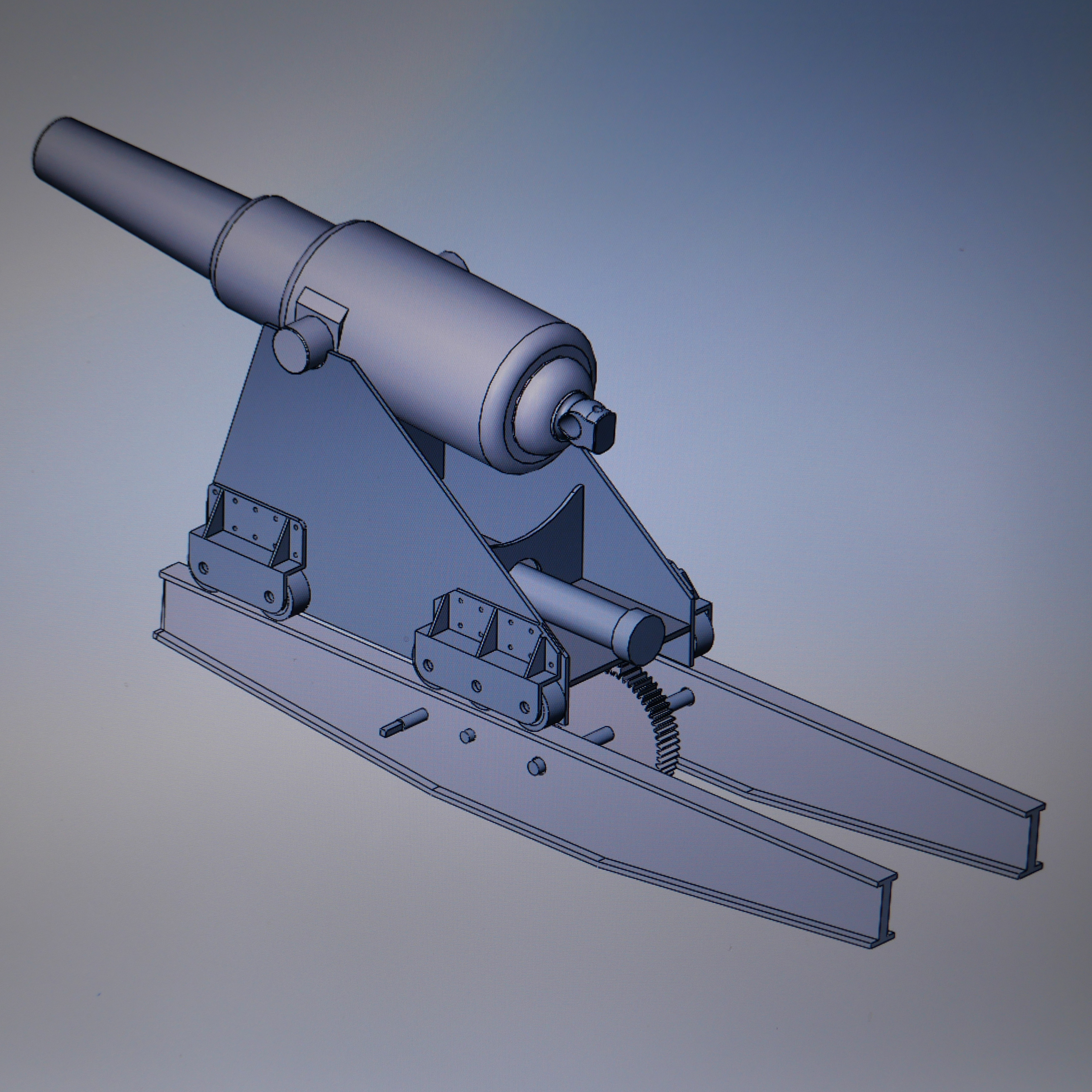
Making a Scale Model Wooden Slide and Carriage for an Armstrong Cannon

Working with wood. It is quite nice to get back into the woodworking. And slightly daunting. Those saws can remove a finger or a limb in an instant of inattention. I use a 12″ radial arm saw, and an 18″ bandsaw. Somehow, the woodworking tools seem more dangerous than the mill or lathe. However, having seen videos and pictures of metal working lathe accidents, where an arm was ripped off at the shoulder, and similar, I know that they are ALL dangerous. At the time of writing I still have all of my bits.

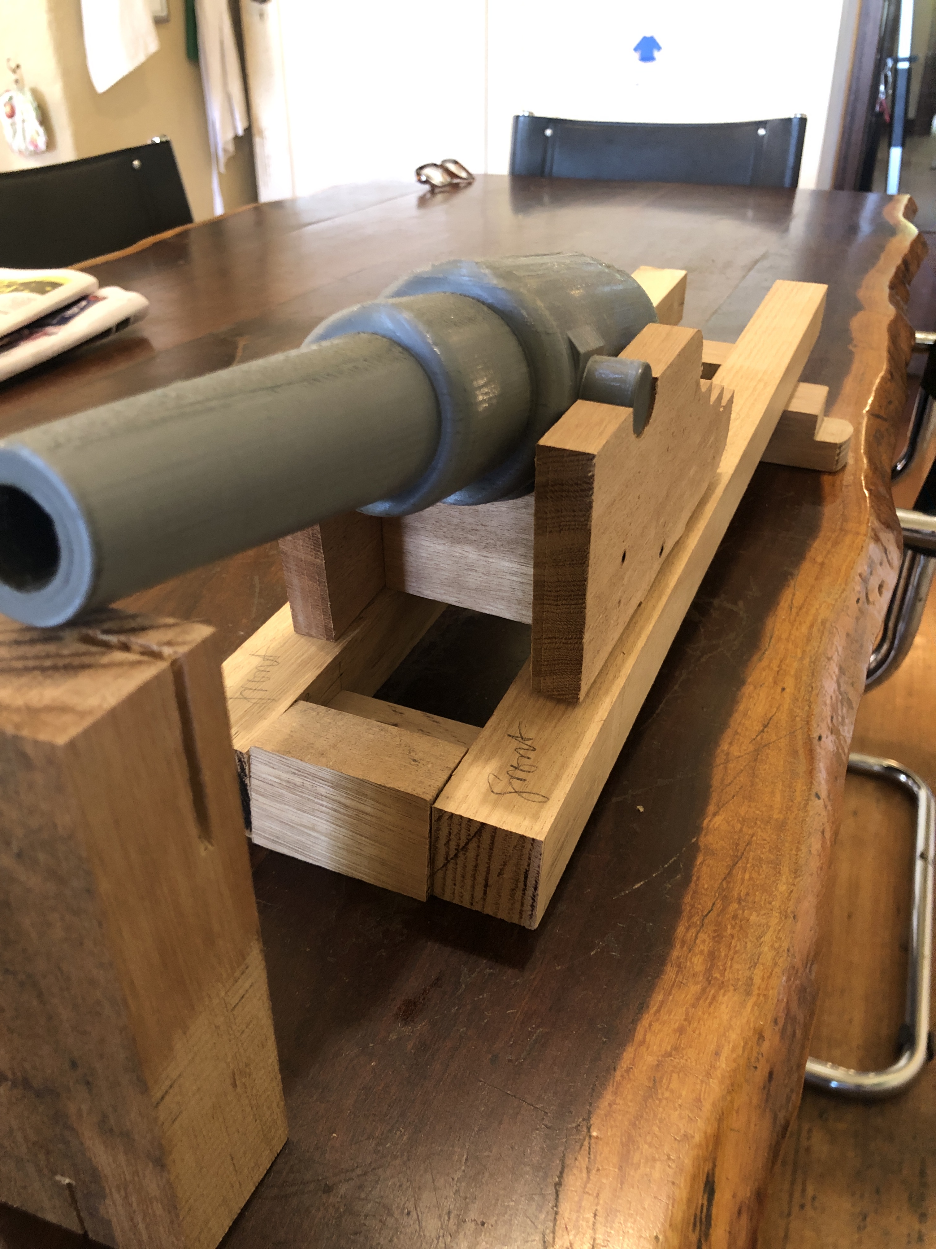
At 1:10 scale, the wooden beams which form the base for the slides are 488mm long, and 30x30mm square section. They have a 5º slope back down to front.

I am using Victorian mountain ash, a pale, tight grained hardwood, and I happen to have some offcuts in my hoardings.

The wood is thicknessed to size, and the ends cut at 5º on the radial arm saw, which I bought about 45 years ago. Back then, B&D/DeWalt was considered a quality brand. I have previously decided which faces will be top and sides, depending on appearances.
checking cuts for squareness at the correct angle.
And today I used the CNC mill to cut out the carriage sides. 15mm mountain ash. The holes were drilled first, then brass pins hammered into the ash and the sacrificial base. Then the outside shape routed with a 6mm metalworking endmill. Some sharp internal corners will need to be filed or cut later.
I use a high speed spindle to do the routing at ~10,000 rpm.
Propping some bits together to get an idea of the size. The barrel is 3D printed plastic.

Oh. And some really useful woodworking tools which I bought from Banggood last year, and used for the first time on this project. They are laser cut spring steel, with holes and slots at 1mm and 0.25mm intervals, and a propelling pencil for marking. Accurate by woodworking standards, and they work really well, and were not overly expensive ($15-20 from memory).

And another bit of technology which I find useful with this project….

This is a plan of a 110pr Breech loader sitting on a wooden slide and carriage. I think that it is the one which was modelled by Jefenry which appeared in the video from my post of a day or two ago. On close inspection, it appears almost identical to the slide and carriage for my Armstrong 80pr. The width is different, due to the larger diameter of the breech loader barrel.

By fiddling with the magnification settings on our printer, I was able to print the plan on A3 paper, at a scale of 1:2 of my 1:10 model. The plan is quite accurate, allowing me to measure off dimensions of the components, angles and so on. This has been really useful.

Note that the wooden assembly is held together with large nutted bolts. And mortise/tenon joints as revealed by the Warrnambool LowMoor cannon. I will use bolts, and brass dowels, because MT joints are fiddly, difficult to make accurately, and will not be visible.

Armstrong 80pr Cannon Wooden Chassis

So, today I battled 1.5 hours of post covid lockdown Melbourne traffic to take a closer look at the wooden slide and carriage of this 1866 Armstrong RML cannon which I am intending to model. There are 2 of them in the Hopetoun Gardens, Elsternwick. They are more complex than I had imagined.

The barrel is identical to the barrels which I had modelled on iron slides. The iron slides were a later improvement – modification.

It was a beautiful spring 20ºc day. I spent almost 3 hours photographing and measuring the wooden components. Some parts have been restored, and it was lucky that there are 2 examples to check and compare.

I was climbing over and under the cannon, and groundsman came over to check. Then a pair of grandparents came over with their 5 yo grand-daughter, and a further pleasant conversation followed.

Some examples of the photos…..

And an example of many pages of measurements and sketches…

There are 11 pages filled with details like this, representing my 3 hours.

And I still do not understand how the barrel elevation mechanism functioned. It could have been a wooden wedge called a quoin, but there appears to be a metallic disk set into the wooden bearer. Could there have been a screw mechanism which has since been removed/stolen/lost? Pictures on Google Images do not help. Does anyone know?

Armstrong Cannon Chassis Wheel Assemblies

The steel chassis is virtually finished, although I am delaying inserting the final rivets which join the girders together, in case I need access to the individual girders for more machining or drilling.

PANA3825

The 2 chassis’ are not identical.  Can you spot the differences?  And still waiting for more rivets to arrive.  The copper colour on the front one resulted from dipping it in well used sulphuric acid after some silver soldering.


Considering how to model these wheel assemblies…..

front wheel and mounts

The front wheel assemblies

rear wheel and support

The rear wheel assemblies

The rear wheels and supports are larger than the front ones.  But the top views are essentially the same.  The wheels themselves present no difficulties.  They will be turned from 50mm diameter steel rod.  And the axles will be all identical.

But, those supports are complex, and will need to be silver soldered parts, or possibly cast from 3D printed lost PLA bronze or brass.  Just drawing them was challenging.

This is a complex project, and the parts are complex.

Considering that the original cannon barrel was made in 1866, and the steel/iron chassis made approximately 20 years later (the original barrels were mounted in a wooden carriage),  the standard of the workmanship in the originals is simply superb.   Even at 1:10 scale, and using modern equipment including CNC machinery, I am struggling to match the standard of fitting steel pieces together so neatly.  I am in awe of the original engineers.

(and by the way.  Neil M, who very kindly loaned me the rivet gun which died, has loaned me a replacement gun.  The replacement gun is a bit bigger, and more fierce.  It requires more care in not overdoing the hammering, and bending the steel parts or producing “two-bobs” in the work piece.  “Two-bobs” will be understood only by older Aussies?  They are unintended dents in the workpiece produced by hammering.)

Small Steps. Armstrong Cannon.

6 hours in the workshop today.  I am constantly surprised at how little progress appears per session.  Also surprised at how quickly the time passes.

I had left the external dimensions of the cannon chassis girders rectangular, to facilitate holding the items, while doing as many machining processes as possible with the rectangular shape.  But today I bit the bullet, and made the final girder shape.

PANA3776

There is a 4º angle at each end, and a 6º slope along the bottom of each girder.  Also, the top flange is 11.5mm wide, and the bottom flange is 14mm wide.

PANA3773

Setting up for the bottom 6º angle.  The 4º ends had been machined before this.

The 4 girders are all looking good.  Next to start making end pieces and brackets.  I am still waiting for rivets to arrive, so the assembly will be bolted together initially.

Armstrong RML. The Chassis -1


I will start by making the main girders.  At 1:10 scale they will be 400mm long, 11mm wide and 46mm deep.  Some fabrication will be required.

P1053549

Many rivets required.  I will need to improve my riveting skills.  One issue to be decided. Do I use copper (easy) or steel rivets (authentic)?.  Whichever, they will be eventually painted the same colour as the girders.


chassis R rear obl

And another decision.  Your opinions invited.  2 methods for fabricating the girders.

TIG weld the flanges top and bottom (right).  Or, (left) join 2 pieces of angle iron, then TIG weld the bottom flange.  I don’t like the top groove to be filled.  I do not really want to paint the surface that the carriage wheels roll along.

It is a very long time since I did any TIGging, so maybe some practice runs first…

P1053742

And another option comes to mind….   just to machine the shapes out of solid bar.  I think that I will try TIG first.

Later….   just remembered.  I don’t have any TIG gas.  Easter.  Bum.  OK.  Back to square one.  Maybe I will try to mill the shape from bar…..