johnsmachines

machines which I have made, am making, or intend to make, and some other stuff. If you find this site interesting, please leave a comment. I read every comment and respond to most. n.b. There is a list of my first 800 posts in my post of 17 June 2021, titled "800 Posts"

Tag: CNC mill upgrade

CNC Mill Upgrade -5

I have been putting quite a few hours into the upgrade, but not much to show photographically.

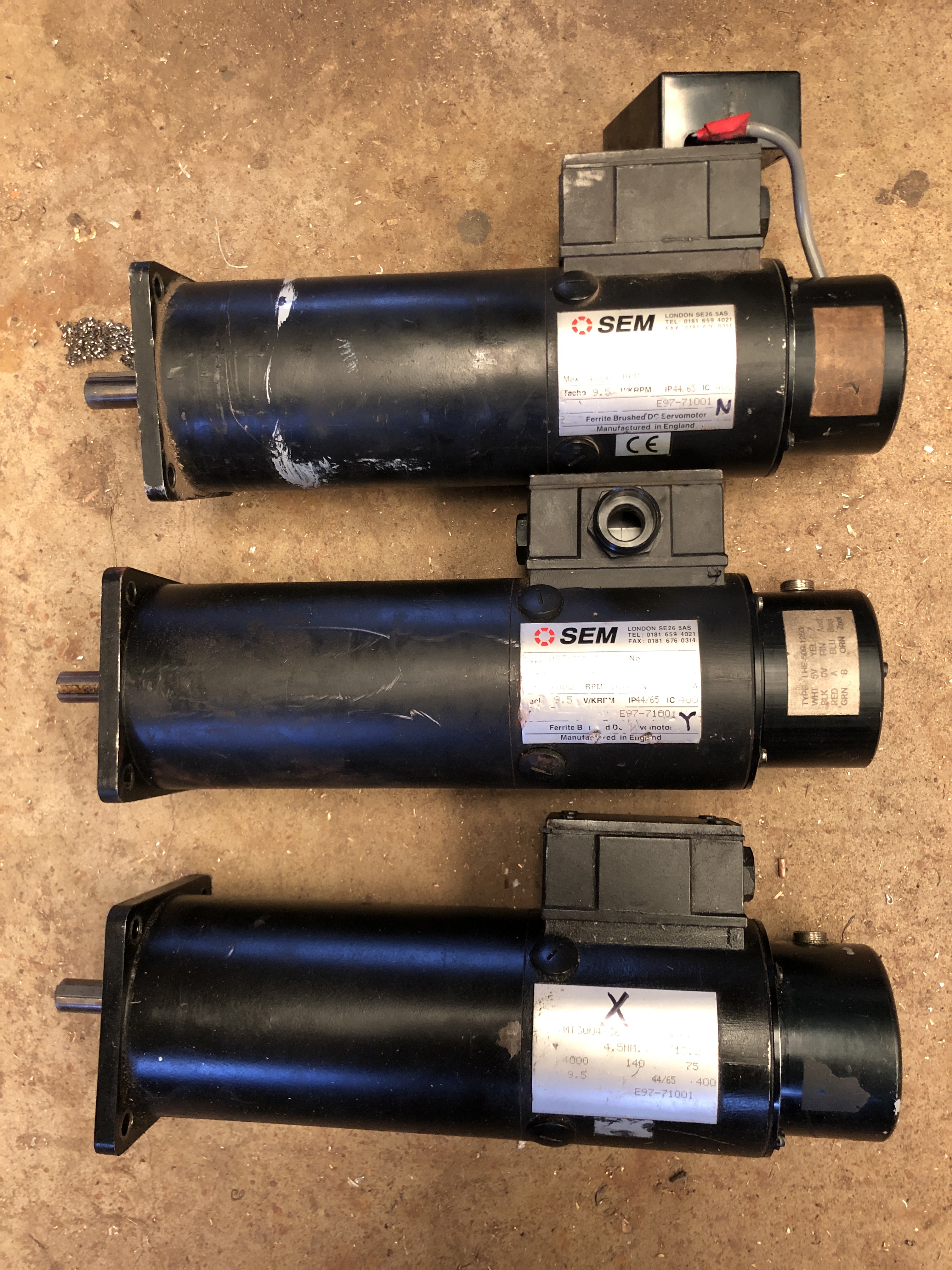
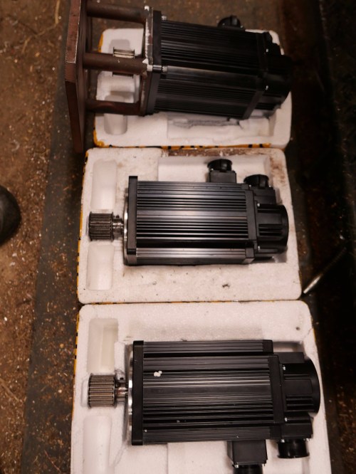
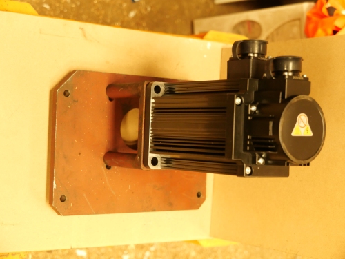
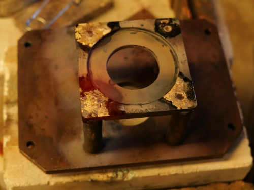
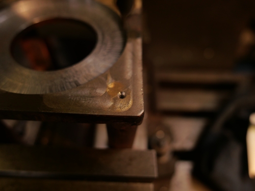
Finally got the new servo motors installed.  Replaced the X axis belt.  The most difficult servo to access was the Y axis, and of course that was the only one where the alignment of the timing belt was out.   Finally sorted by using a fibre optic camera to see why the belt was climbing onto the flange of the pulley.  The pulley was 1.2mm too far onto its shaft.  I know that, because I solved the problem by inserting washers under the motor mounts.  1mm washers did not work, nor did 1.5mm washers.  But 1.2mm washes did work perfectly.

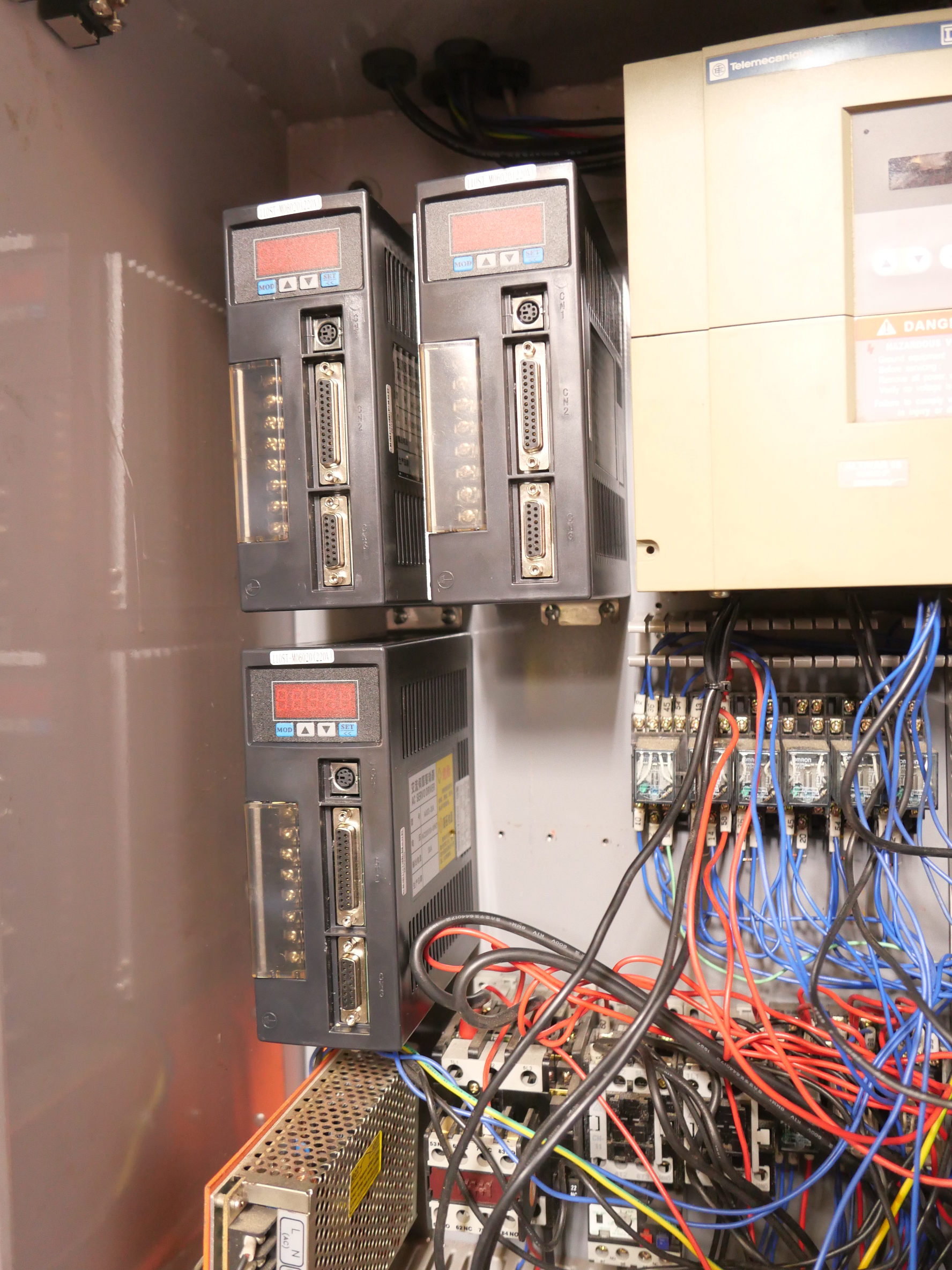
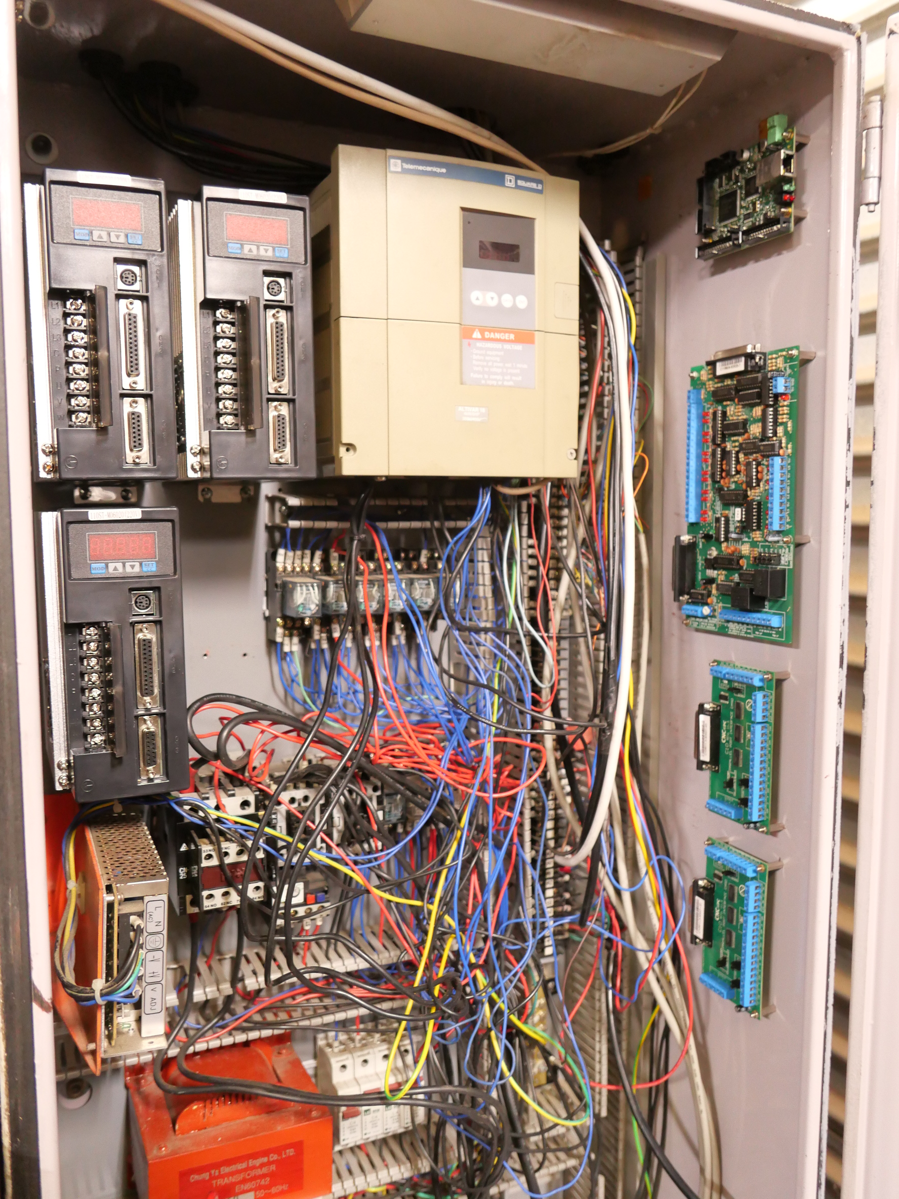
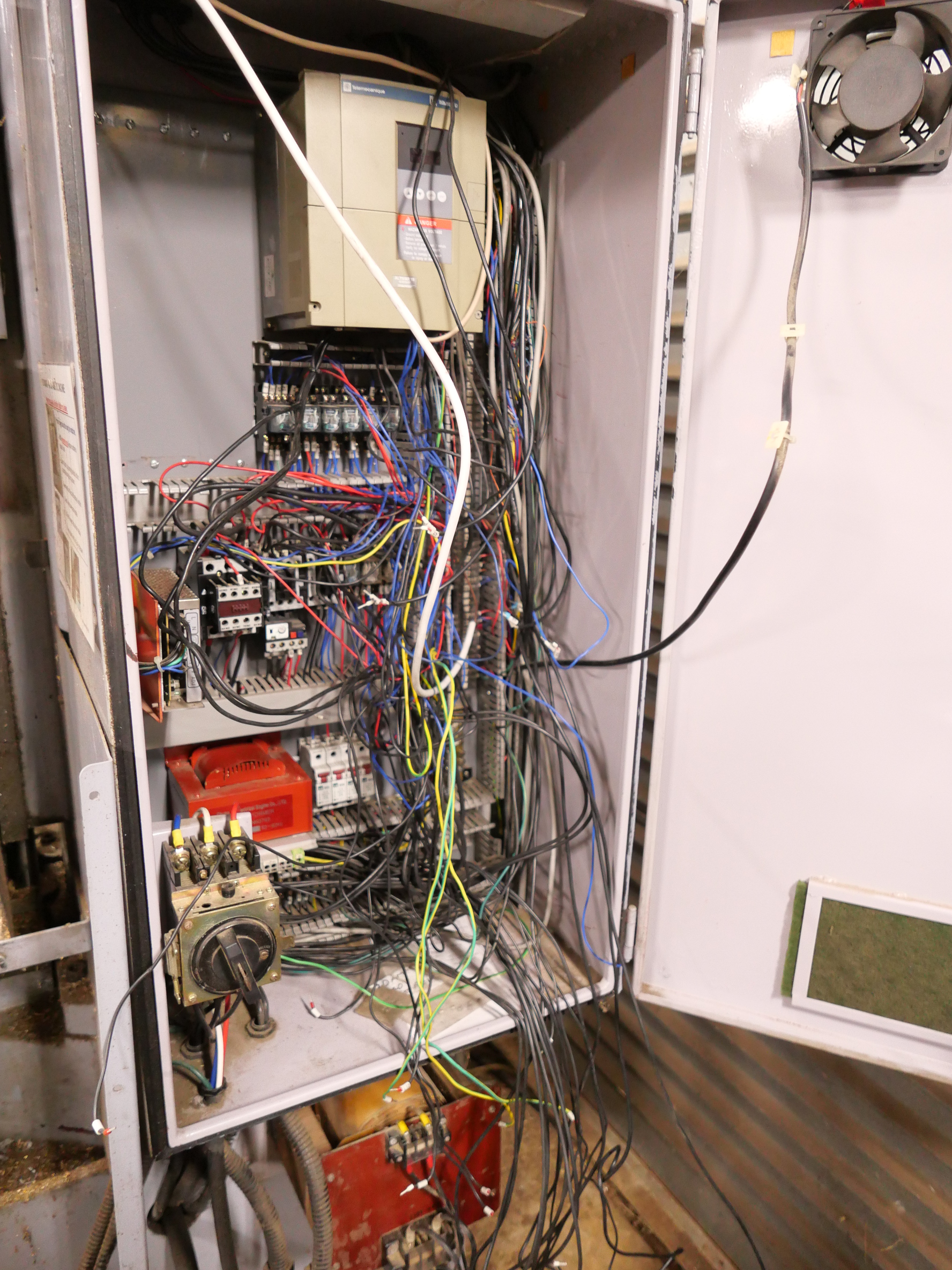
Today Stuart arrived and removed more of the old wiring.

P1032880.JPG

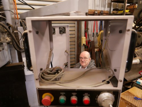
Stuart, doing another CNC upgrade wiring.

P1032881.JPG

The old 7k computer has been removed, leaving some buttons.  I might be able to use those. The computer enclosure might disappear too.  Not decided yet.

P1032882.JPG

The old CNC mill has lost some weight.  Those cartons are full of old parts.  Note that the floor has been swept.  Stuart was concerned that we might be infested with snakes, but it is winter here, so we should OK until the weather warms up.

P1032883.JPG

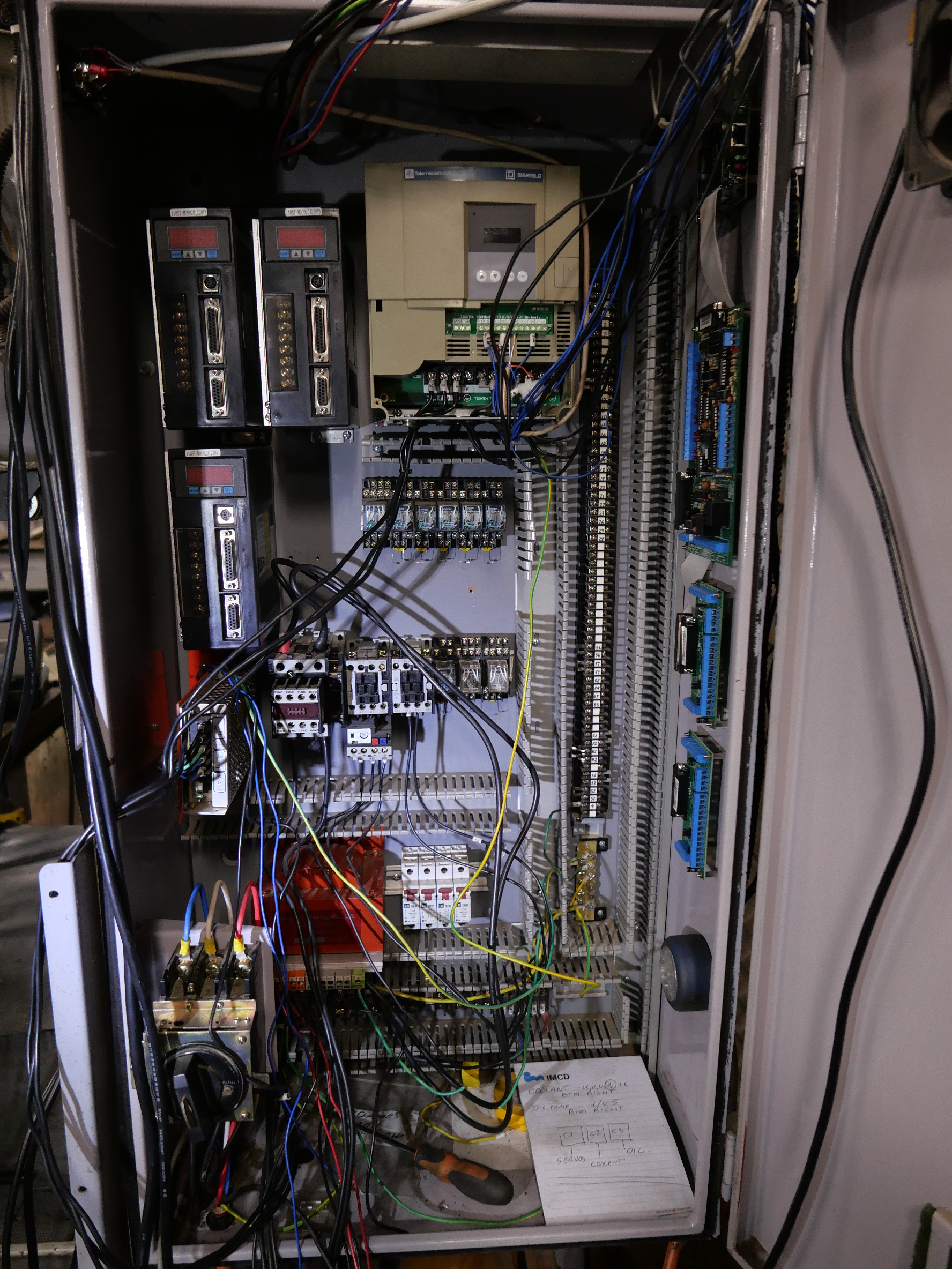
The rats nest is disappearing.

CNC Mill Upgrade -4

I removed the old XY & Z axis servo motors from the mill.  Each one weighs about 15kg (33lb).

IMG_8119.JPG

The old servo motors.  The X and Z were working fine.  The Y was faulty, but I do not know whether the fault was in the motor, the encoder, the controller, or the connecting wires.  I will put them on Ebay as 2 working, one for parts.

Then I removed the belt drive pulley off each motor.  There was a grub screw, which would not budge.  Assuming that it had been Loctited, I applied some heat, judiciously.  The grub screw came out, but the pulley would not budge, so a little more heat, and a gear puller.   Two of the gears came off, but one still would not budge.

I asked for advice, and I was loaned a different type of gear puller. (thanks Rudi).  This time, some movement of the gear on the shaft was noted, and eventually the last motor gave up its gear.

img_8122.jpg

This one worked.

The shaft of the old motors was 16mm diameter.  The new motors had 19mm shafts.  So I spent some time on the lathe boring out the gears to fit the shafts of the new motors.  The keyways of the old motors were 5x5mm, and the new ones were 6x6mm.  So, I borrowed a 6mm broach (thanks Stuart), and enlarged the keyways in the rebored gears to 6mm width.   The new keyways needed a lower profile, so some time on the mill and surface grinder  to reduce the thickness of the keys to 4.5mm.

That was quite a few peasant hours hours on the lathe, mill, and surface grinder, but the end result was good.

P1032877.JPG

The new servo motors, with the timing belt gears fitted, with keys in place.  I will set each motor in place on the CNC mill, determine the final exact position of the gear on the shaft, then indent the shaft for the grub screw.  Then, when I am sure that all is correct, the gear, grubscrew and shaft will be Loctited.

Another small issue was that the boss on the new motors was 5mm deep compared to 3.5mm deep for the originals.  So the mounting plate for each motor needed the recess to be deepened by about 1.5mm.

P1032878.JPG

I used a boring head on the mill to deepen the first one, but it did not produce a good finish, so the next 2 (shown) were deepened on the lathe, in a 4 jaw chuck.

Meanwhile, back to the rats nest in the electric control enclosure….


P1032875

The bare space top left is where the old servo controllers lived.  They were removed.  Then I spent a half day tracing each wire from the controller to the old servo, and removing it.  That produced a carton full of wires.  The rats nest is now a little less tangled.  A lot more of those wires will be removed as the job progresses.

P1032879.JPG

The new servo controllers bolted into position.  They are fatter than the originals, so a bit of rearranging was required.  The yellow box top right is the main spindle speed control (VSD) which is being retained.

P1032876.JPG

And on the right hand side, newly bolted into position today, from the top down, are the smooth stepper, the C11 breakout board, and two C10 breakout boards.   Awaiting some expert wiring.  (Stuart, are you reading this?)


Upgrading the CNC mill -3. Moving a threaded hole in steel plate.

P1032869.JPG

this is the new Y axis servo motor, sitting on its mounting plate, after the old servo has been removed

P1032863.JPG

Unfortunately the existing M8 threaded holes in the mounting plate are just in the wrong position for the new motor’s 8mm mounting holes.

So, do I 1. make a new mounting plate and assembly?   2. machine or file the new motor’s holes to fit the old plate?   Or 3. Fill the old mounting plate hole, then drill and tap new holes in the correct position  ??

  1.  seemed a lot of work   2. would have looked ugly and probably voided the motor’s warranty      3.  Seemed tricky, but I decided to give it a go.   If unsuccessful I could always revert to 1.

Filling the old holes.  Could have used steel thread and silver soldered it into place.  In retrospect, would probably have been the best option.   Could have used steel thread and Loctited it into place…. decided against, in case subsequent machining  softened the Loctite.   Could have filled the old holes with bronze, and drilled and tapped new threaded holes….   well, for better or worse, that’s what I decided to do.

The new holes impinged about 25-33% on the old holes.

P1032870.JPG

The old holes were bronzed.   I improved my technique as I moved around the holes.

P1032871.JPG

After cleaning up on the mill, the new holes were center drilled 

P1032872.JPG

Then drilled to size, and tapped.  revealed that the bronze did not entirely fill the voids. 

P1032874.JPG

I wondered if the bronze would accept a suitable degree of tightening of the M8 cap screws, but all seemed fine.   Note the jacking bolts, to prevent distortion of the weldment in the milling vice.

The bronze-steel sandwich did cause the tapping drill to wander slightly, but not enough to cause concern.  Next time I will try silver soldering in a steel filler piece.

Meanwhile, I have been removing parts and wires from the electrical enclosure.

P1032875.JPG

The servo controllers are removed.  Bit of a rats’ nest hey!  About 90% to go…