
CNC Mill Upgrade -4
by John
I removed the old XY & Z axis servo motors from the mill. Each one weighs about 15kg (33lb).
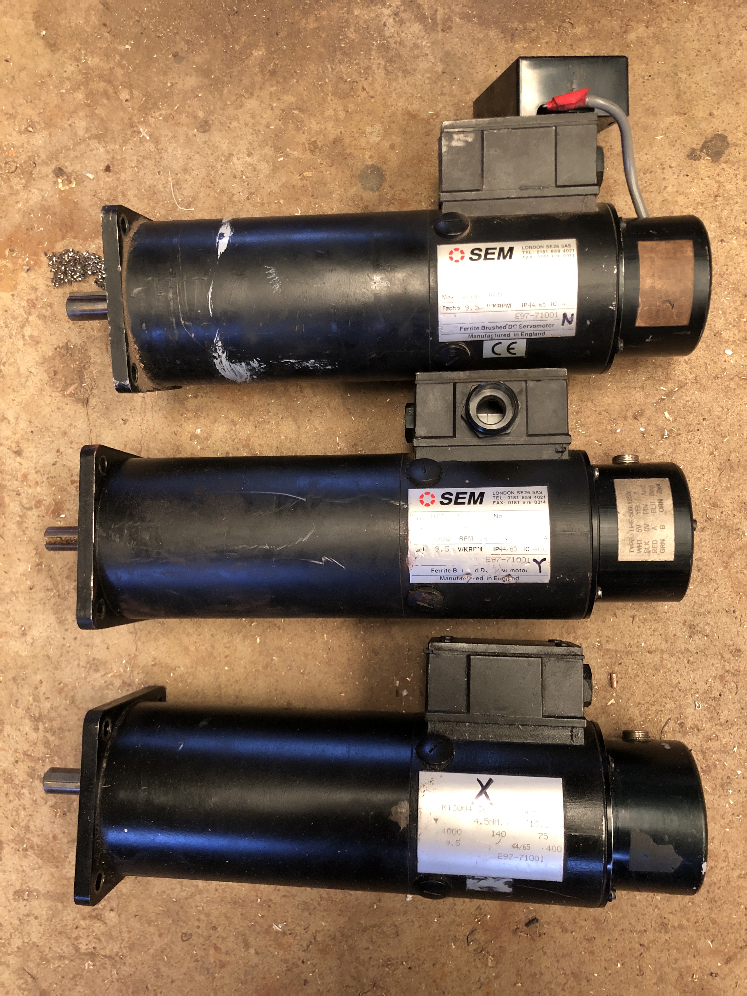
The old servo motors. The X and Z were working fine. The Y was faulty, but I do not know whether the fault was in the motor, the encoder, the controller, or the connecting wires. I will put them on Ebay as 2 working, one for parts.
Then I removed the belt drive pulley off each motor. There was a grub screw, which would not budge. Assuming that it had been Loctited, I applied some heat, judiciously. The grub screw came out, but the pulley would not budge, so a little more heat, and a gear puller. Two of the gears came off, but one still would not budge.
I asked for advice, and I was loaned a different type of gear puller. (thanks Rudi). This time, some movement of the gear on the shaft was noted, and eventually the last motor gave up its gear.

This one worked.
The shaft of the old motors was 16mm diameter. The new motors had 19mm shafts. So I spent some time on the lathe boring out the gears to fit the shafts of the new motors. The keyways of the old motors were 5x5mm, and the new ones were 6x6mm. So, I borrowed a 6mm broach (thanks Stuart), and enlarged the keyways in the rebored gears to 6mm width. The new keyways needed a lower profile, so some time on the mill and surface grinder to reduce the thickness of the keys to 4.5mm.
That was quite a few peasant hours hours on the lathe, mill, and surface grinder, but the end result was good.
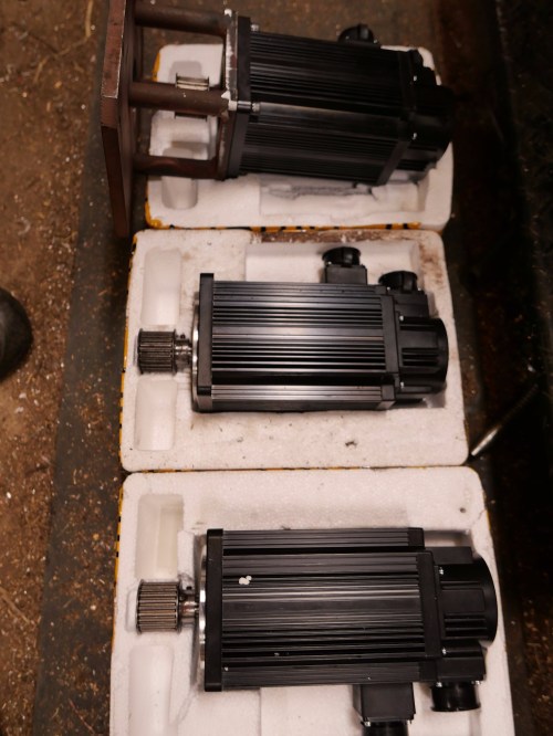
The new servo motors, with the timing belt gears fitted, with keys in place. I will set each motor in place on the CNC mill, determine the final exact position of the gear on the shaft, then indent the shaft for the grub screw. Then, when I am sure that all is correct, the gear, grubscrew and shaft will be Loctited.
Another small issue was that the boss on the new motors was 5mm deep compared to 3.5mm deep for the originals. So the mounting plate for each motor needed the recess to be deepened by about 1.5mm.

I used a boring head on the mill to deepen the first one, but it did not produce a good finish, so the next 2 (shown) were deepened on the lathe, in a 4 jaw chuck.
Meanwhile, back to the rats nest in the electric control enclosure….

The bare space top left is where the old servo controllers lived. They were removed. Then I spent a half day tracing each wire from the controller to the old servo, and removing it. That produced a carton full of wires. The rats nest is now a little less tangled. A lot more of those wires will be removed as the job progresses.
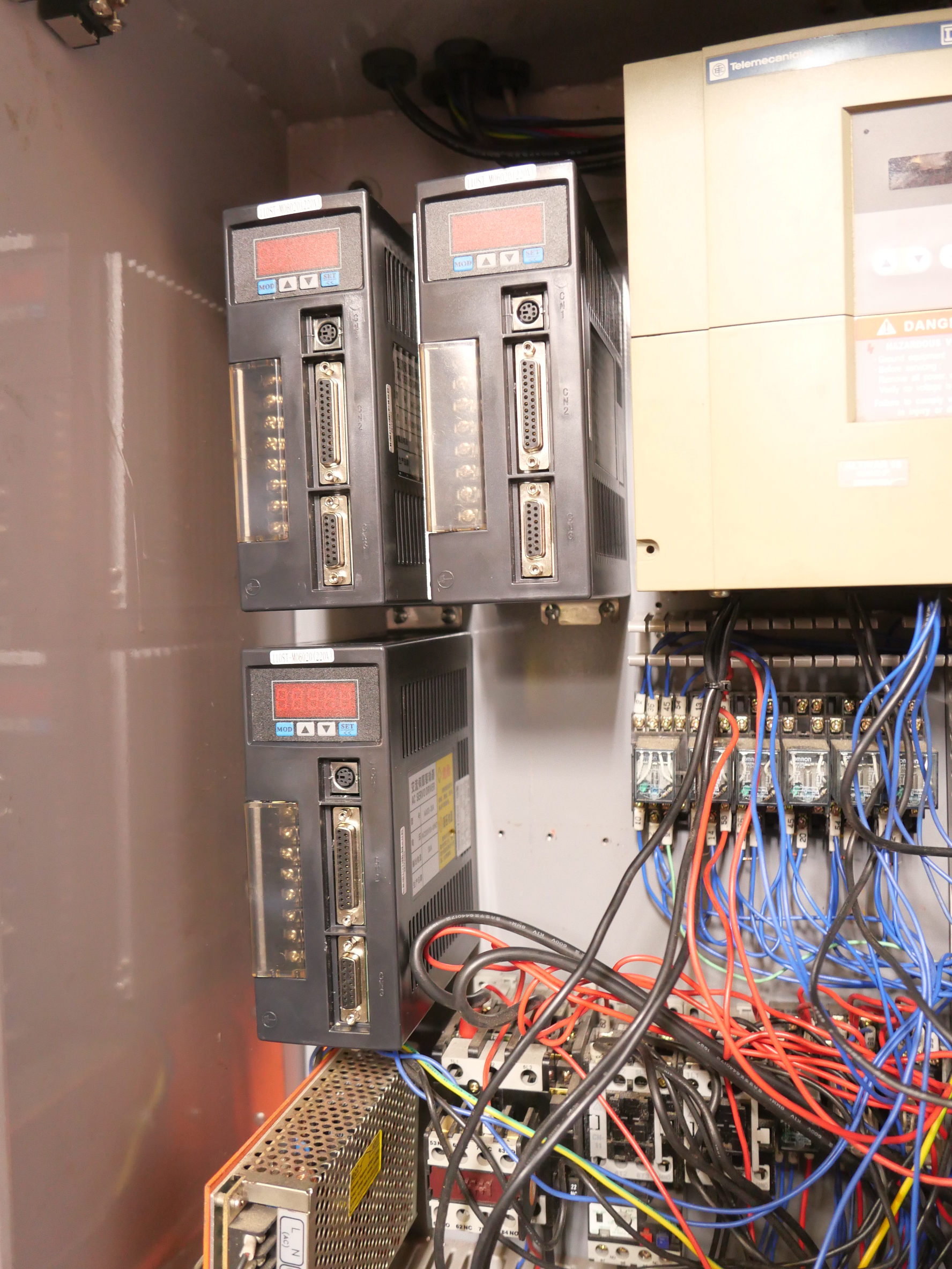
The new servo controllers bolted into position. They are fatter than the originals, so a bit of rearranging was required. The yellow box top right is the main spindle speed control (VSD) which is being retained.
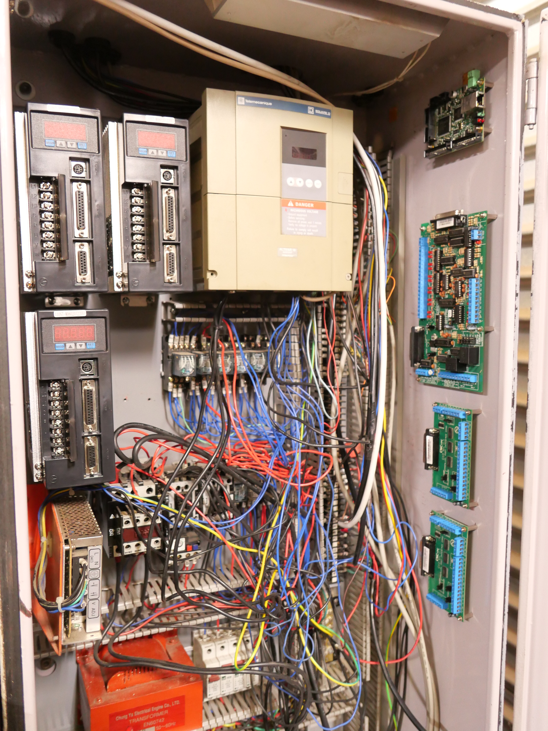
And on the right hand side, newly bolted into position today, from the top down, are the smooth stepper, the C11 breakout board, and two C10 breakout boards. Awaiting some expert wiring. (Stuart, are you reading this?)

excellent work John. Progress slow but methodical, assures that it is done correctly. Hopefully won’t be long before it is all new again. Then the parts will roll off the machine. Bye, my first reply on your blog. Les M
LikeLike
Thanks Les. As you can see, I am availing myself of lots of help and advice. John
LikeLike
Hi John,
Those are some super heavy duty steppers. Do not let them go too cheap.
Been making a big push on my beam engine, I’m so close to having all the parts gone that I can taste it.
I have begun ramping up on my Anzani 3 cylinder radial 1/4 scale. It’s a copy of the 1909 (give or take a year or two) engine that Santos DuMont flew across the channel.
I’ve had the few castings that are still available for almost a year now. The cylinder patterns were lost to time so I will have to make them from scratch out of iron. A CNC machine would be nice for that job.
The plans were drawn by the late John Chennery, an engine builder of note and one heck of a draftsman. His son sells the plans and a guy I know had the patterns got the crank case halves and carb body.
Keep us posted!
Jenny
LikeLike
Hi Jenny!
the servos are $US3500 each new. But these are 22 years old, and one has a problem. They might be useful for someone who doesn’t want to do a total electronic rebuild. But I will just sell them for what they will bring on Ebay.
Tell me, did you ever get the plans for the Don River engine? I would be interested to make that as a model!
Nice to hear from you John
LikeLike
Not yet John.
I plan on going there on my way to the Midlands model engineering show in October.
I will photograph everything that they have, which according to the person I spoke to the week after we were there are s complete set of drawings.
I imagine it must be hundreds of full size real blueprints, I am allowing two days to copy everything, hopefully everything is there.
I’ll dump everything to s jump drive and nail it to you when I am done.
I would like to use them to make a set of plans made for model engineering, including s bill of materials.
Btw it looks like it just takes some time got munpostd to appear,
Thanks for replying,
Jenny
LikeLike
Hi John,
When I look at that wiring it’s knit one pearl two.
Hats off to you for taking on such complexity. What a thrill when it all comes together…which I’m sure it will.
Tim
LikeLike
Ha Ha. Ratsac rather than knitting needles I think.
LikeLike
Hi John
Progressing nicely, love watching jobs like this progress slowly and seeing the results keep at it.
Cheers
John
LikeLike
Great seeing the progress on the Mill. Quite a challenge getting all the New bits to mate up to the old. Quite impressed how the control cabinet is coming together and fitting all the new components in.
LikeLike