johnsmachines

machines which I have made, am making, or intend to make, and some other stuff. If you find this site interesting, please leave a comment. I read every comment and respond to most. n.b. There is a list of my first 800 posts in my post of 17 June 2021, titled "800 Posts"

Tag: Mach 3

Melbourne Society of Model and Experimental Engineers. Xmas meeting.

The December meeting includes the competition for best model, best workshop tooling, and best engine.  The 3 happy winners were all from Geelong.

78947095_10218922337503859_5458110964505247744_o

Stuart Tankard, John Viggers, Swen Pettig

79025950_2448598021904988_6639730611655278592_o

Trevithick dredger engine model by John

78899194_2448597938571663_1550976217446875136_o.jpg

79084789_2448598095238314_3887537897913450496_o

CNC lathe tools, toolholders and toolpost milling attachment by Stuart.

Following is a video of Stuart’s toolpost milling attachment in action.  It has been posted before, but is worth watching again.  It is quite remarkable.

(Photo of the flame gulper to be added.)

But, the best part of the meeting was this demo of a model aeroplane which was made by Don.  The plane weighs 2.5 grams!!!   The wing material is mylar which is 1 micron thick!!!  The flight was cut short by hitting a ceiling projector, but apparently the world record for a flight by a similar plane lasted for over an hour!  This YouTube video has had 360,000+ views in 5 days!


CNC Mill Upgrade – 6. Where to put the computer?

Not much more to report today, but I have decided how to position the computer.

Not easy, because the computer needs to be protected from flying swarf and coolant spray from the CNC mill and the manual mill which is immediately adjacent.    And I want the computer to be close to the machine.  The CNC mill is NOT in an enclosure.

So this is what I have decided….

IMG_8128.JPG

The laptop is just low enough to reach while standing.   The E stop and other buttons are underneath.

And if the swarf is really flying, I can turn the PC away…

IMG_8129.JPG

Might need some adjustments.  The laptop is an old Dell ATG.   Said to be resistant to fluids and relatively resistant to shock/vibration etc.   Military specs.   I might add some side protection and perhaps a roof.


CNC Mill Upgrade -5

I have been putting quite a few hours into the upgrade, but not much to show photographically.

Finally got the new servo motors installed.  Replaced the X axis belt.  The most difficult servo to access was the Y axis, and of course that was the only one where the alignment of the timing belt was out.   Finally sorted by using a fibre optic camera to see why the belt was climbing onto the flange of the pulley.  The pulley was 1.2mm too far onto its shaft.  I know that, because I solved the problem by inserting washers under the motor mounts.  1mm washers did not work, nor did 1.5mm washers.  But 1.2mm washes did work perfectly.

Today Stuart arrived and removed more of the old wiring.

P1032880.JPG

Stuart, doing another CNC upgrade wiring.

P1032881.JPG

The old 7k computer has been removed, leaving some buttons.  I might be able to use those. The computer enclosure might disappear too.  Not decided yet.

P1032882.JPG

The old CNC mill has lost some weight.  Those cartons are full of old parts.  Note that the floor has been swept.  Stuart was concerned that we might be infested with snakes, but it is winter here, so we should OK until the weather warms up.

P1032883.JPG

The rats nest is disappearing.

CNC Mill Upgrade -4

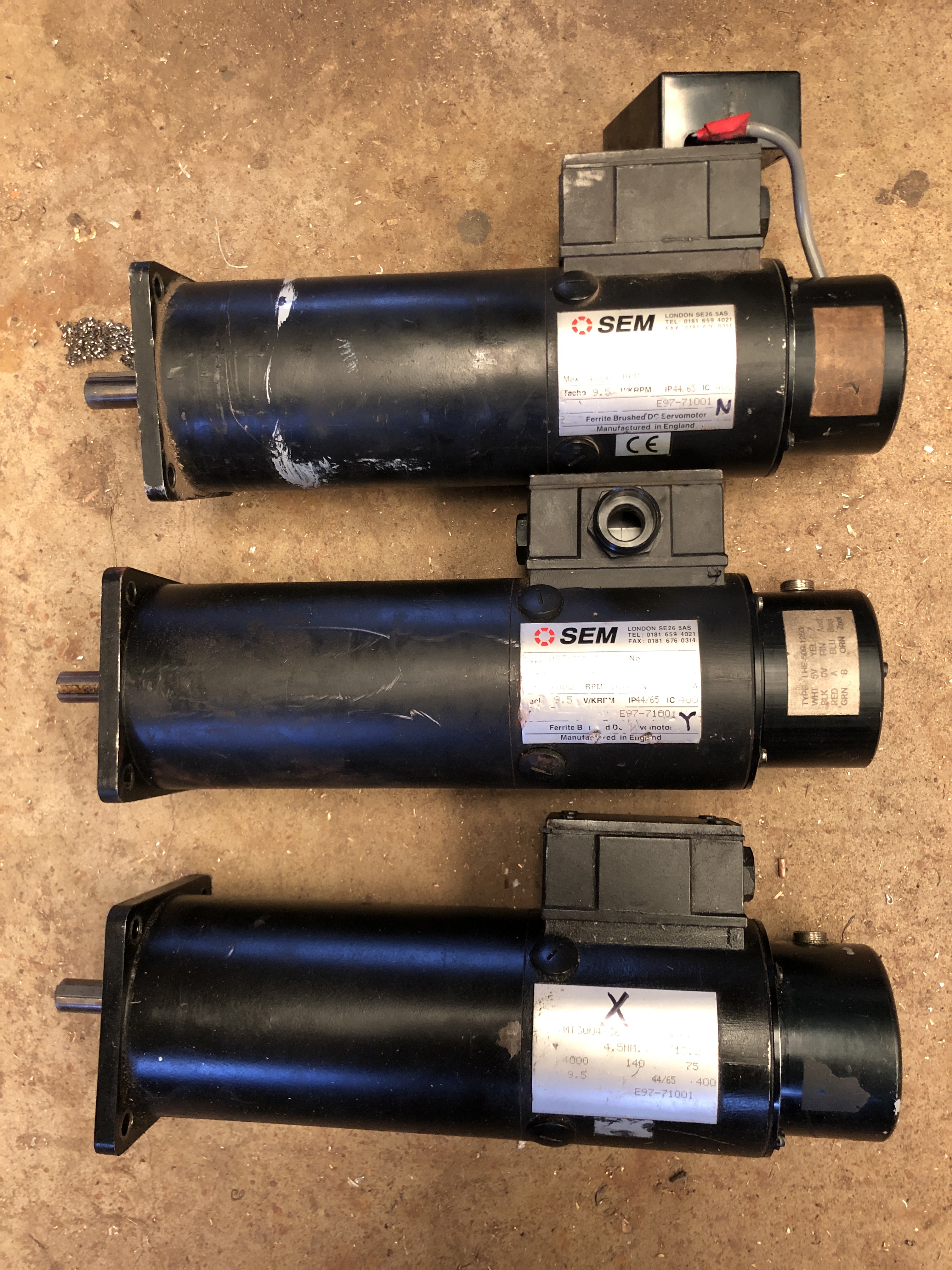
I removed the old XY & Z axis servo motors from the mill.  Each one weighs about 15kg (33lb).

IMG_8119.JPG

The old servo motors.  The X and Z were working fine.  The Y was faulty, but I do not know whether the fault was in the motor, the encoder, the controller, or the connecting wires.  I will put them on Ebay as 2 working, one for parts.

Then I removed the belt drive pulley off each motor.  There was a grub screw, which would not budge.  Assuming that it had been Loctited, I applied some heat, judiciously.  The grub screw came out, but the pulley would not budge, so a little more heat, and a gear puller.   Two of the gears came off, but one still would not budge.

I asked for advice, and I was loaned a different type of gear puller. (thanks Rudi).  This time, some movement of the gear on the shaft was noted, and eventually the last motor gave up its gear.

img_8122.jpg

This one worked.

The shaft of the old motors was 16mm diameter.  The new motors had 19mm shafts.  So I spent some time on the lathe boring out the gears to fit the shafts of the new motors.  The keyways of the old motors were 5x5mm, and the new ones were 6x6mm.  So, I borrowed a 6mm broach (thanks Stuart), and enlarged the keyways in the rebored gears to 6mm width.   The new keyways needed a lower profile, so some time on the mill and surface grinder  to reduce the thickness of the keys to 4.5mm.

That was quite a few peasant hours hours on the lathe, mill, and surface grinder, but the end result was good.

P1032877.JPG

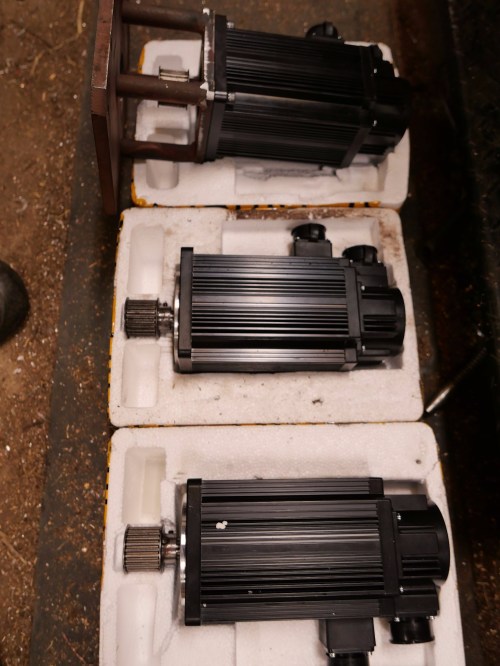
The new servo motors, with the timing belt gears fitted, with keys in place.  I will set each motor in place on the CNC mill, determine the final exact position of the gear on the shaft, then indent the shaft for the grub screw.  Then, when I am sure that all is correct, the gear, grubscrew and shaft will be Loctited.

Another small issue was that the boss on the new motors was 5mm deep compared to 3.5mm deep for the originals.  So the mounting plate for each motor needed the recess to be deepened by about 1.5mm.

P1032878.JPG

I used a boring head on the mill to deepen the first one, but it did not produce a good finish, so the next 2 (shown) were deepened on the lathe, in a 4 jaw chuck.

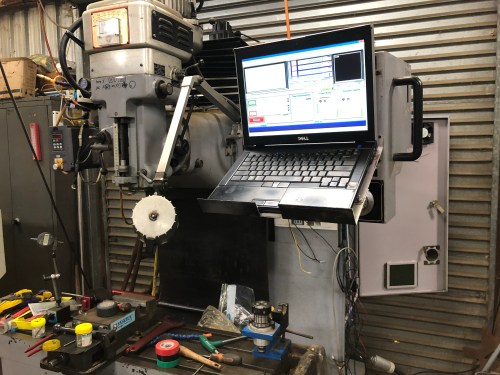
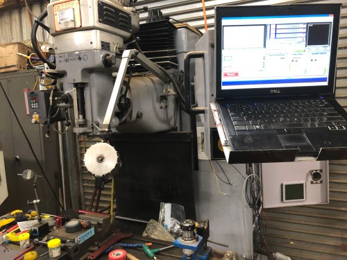
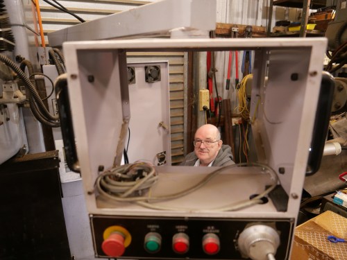
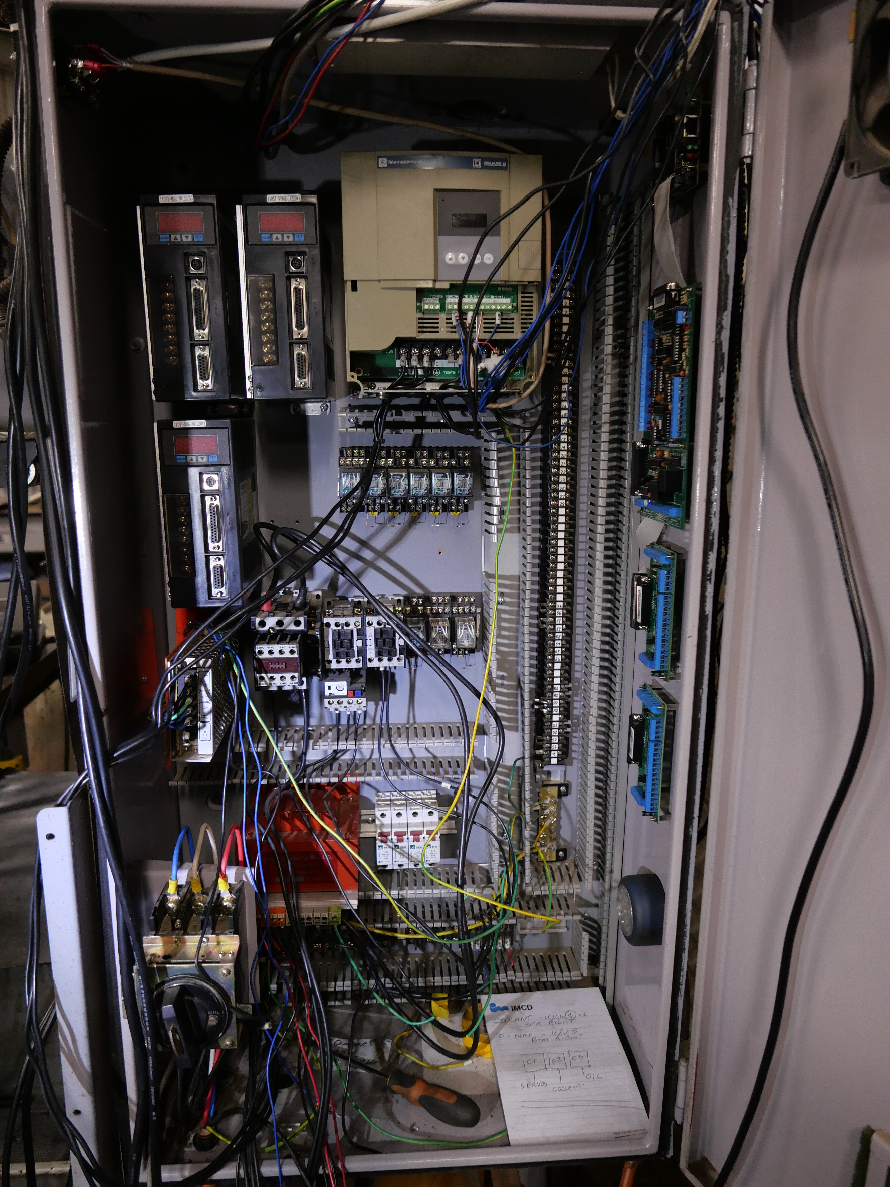
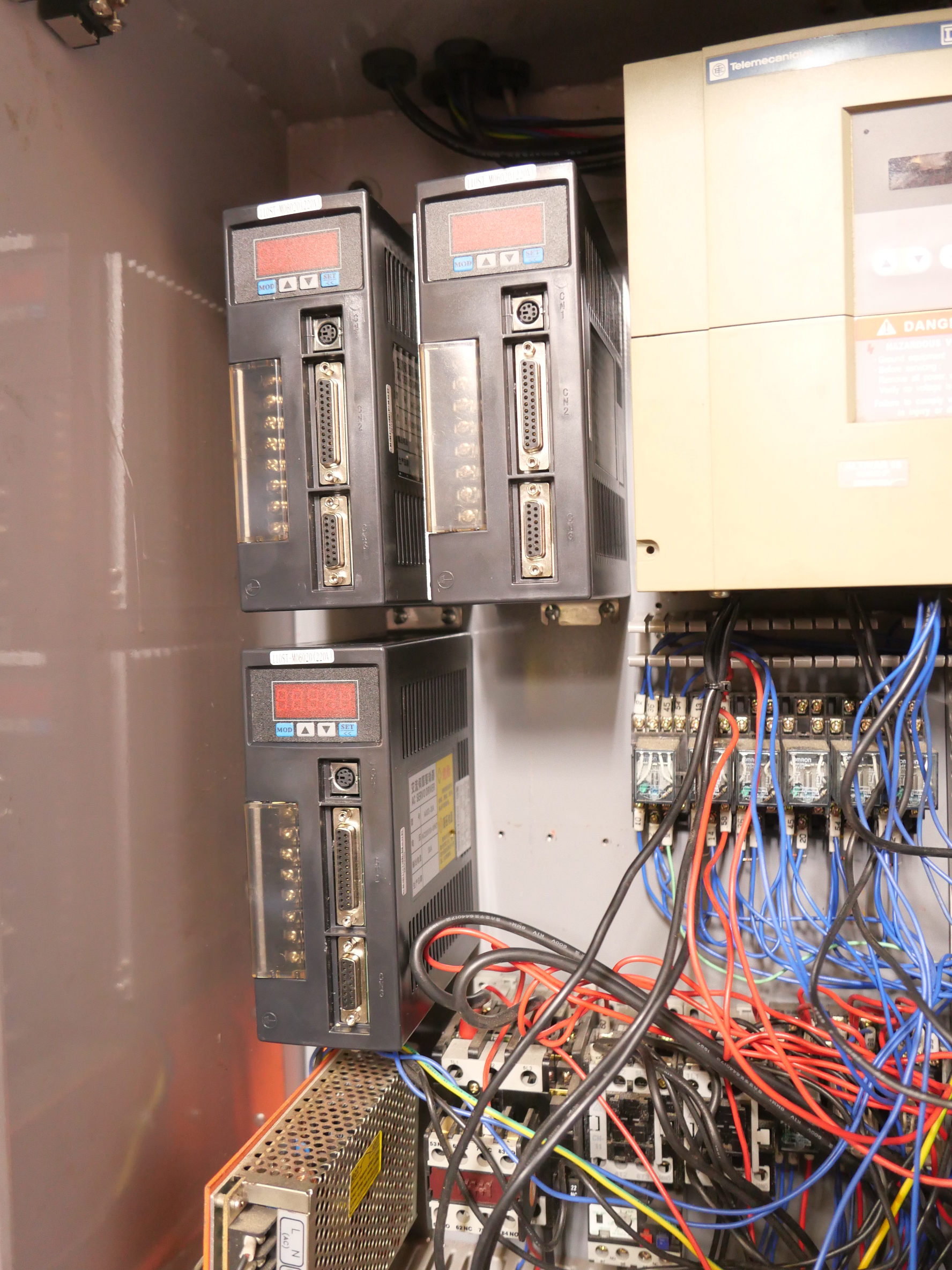
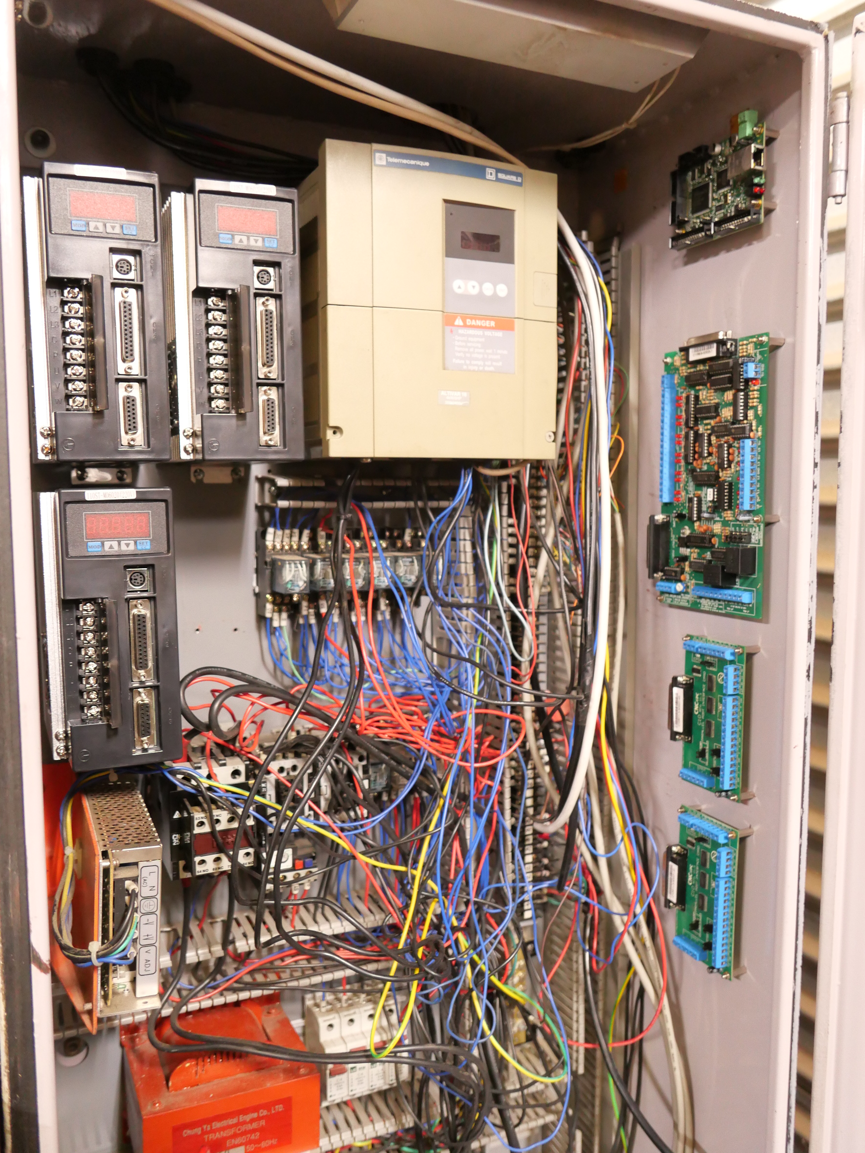
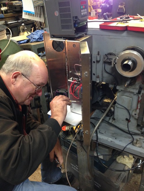
Meanwhile, back to the rats nest in the electric control enclosure….


P1032875

The bare space top left is where the old servo controllers lived.  They were removed.  Then I spent a half day tracing each wire from the controller to the old servo, and removing it.  That produced a carton full of wires.  The rats nest is now a little less tangled.  A lot more of those wires will be removed as the job progresses.

P1032879.JPG

The new servo controllers bolted into position.  They are fatter than the originals, so a bit of rearranging was required.  The yellow box top right is the main spindle speed control (VSD) which is being retained.

P1032876.JPG

And on the right hand side, newly bolted into position today, from the top down, are the smooth stepper, the C11 breakout board, and two C10 breakout boards.   Awaiting some expert wiring.  (Stuart, are you reading this?)


CNC Lathe conversion -16

The wiring of the lathe is complete.  (Except for limit switches.  They can be added at any time).

Mach 3 is configured.  The wireless hand control is installed and working.  Ezilathe installed and waiting for input.

Some covers to be made.

IMG_4154

Hook ups in progress.  That’s the faulty VSD on top of the electronics enclosure.  The CNC engineer lost his hair trying to figure out the problem.

Still some testing and fine tuning required.

But nothing much will happen in the workshop for the next  3 weeks.


Turning a cannon barrel

Today the exterior surface of the model 1779 naval cannon barrel was turned.

The piece of brass material weighed 5.1kg, was 300mm long and 50.8mm diameter.

I had used Loctite to glue a spigott in the bore, to provide a center and a driving diameter which the small CNC lathe would accept.

Although the lathe was nominally 300m between centres, the toolpost would move only about 200mm.  So the turning had to be accomplished by turning the cannon mouth end first, and then reversing the workpiece to turn the breech end.

The CNC lathe, owned by Bob Julian,  is about 30 years old, and it came out of a school.  In the course of this  job, it seemed to progressively free up, making us suspect that this is possibly the first time it has ever been seriously used.

The lathe electronics had been replaced by Stuart Tankard to use Mach3.  The G codes were generated by Stuart’s program “Ezilathe”, which is available as a free download on “CNC Zone”.   It is an excellent CNC lathe program, and I thoroughly recommend it.

I will eventually post some videos of the turning progress, but my Oz internet connection is so slow, that for the moment I will post photos only.

I started by turning a piece of rubbishy pine as a test.

cannon - 1.jpg

That’s me, watching carefully.  Later we installed the swarf cover.

cannon - 3.jpg

The metal turning lathe does not miss a beat chomping through wood.  These are the roughing cuts.  F300mm/min, S800/min.

cannon - 6.jpg

The Mach3 picture of progress.

cannon - 1.jpg

The finished distal half of the cannon barrel in pine.  If I stuff up the brass version at least I can have a wooden barrel. 

cannon - 10.jpg

Roughing the barrel in brass.  1mm cuts, feed 100mm/min.  It took almost 50 minutes for this section, and about 15 minutes for the breech section.

cannon - 11.jpg

The barrel mouth.  No gouging resulting from the 22 degree HSS cutter.

cannon - 14.jpg

Finish was quite good.  Will require minimal polishing with ScotchBrite.

cannon - 19.jpg

The workpiece was reversed in the lathe, the Z zero carefully set, the X unchanged, and the breech end turned.

The starting weight was 5.1kg.  The end weight, including the spigott was 2.9kg.  So at least 2kg of brass swarf, most of which I swept up and saved for possible future use.

Next to machine the trunions and some silver soldering.


BOXFORD CNC LATHE

About 3 years ago I decided that I wanted to see what CNC was about.  I had read some beginners guides to CNC, and CNC programming, but it was obvious that I would need to buy a CNC machine and actually start machining if I was to make any real progress.

Initially I bought a second hand lathe which had been converted to CNC.  It was a Seig C3, and stepper motors had been installed on the lead screw and cross slide screw.  Some low end electronics connected to a PC, and the setup was controlled with Mach3.

Needless to say, this machine gave poor results.  Poor finish, and poor reproducibility of dimensions.  The lathe was low quality to start with, and the CNC components were low end.  I was inclined to blame the lack of ball screws, but in retrospect, that was only one of the many problems.  It did however give me a taste of the process of CNC programming, and finishing with a CNC turned item.  I also developed some familiarity with Mach 3, and became a licensed user of the excellent software.

IMG_1009

Seig C3 converted to CNC. Not up to scratch.


IMG_1011

Then I saw a Boxford CNC lathe, owned by a friend in my engineering club (GSMEE).  It was 30 years old, and had started life as a technical school teaching lathe.  The original electronics and operating system were based on a CPM computer, pre-dating Windows, even pre-dating DOS.  It ran on software which was loaded each session from a 5.25″ floppy disk, with a capacity of 180 kilobytes.

My friend had changed the operating system to  Windows and Mach 3.  That involved changing many of the electronic components in the lathe, and hooking up a PC.

The lathe was an English Boxford TCL 125.  The swing is only 125mm (62.5mm above the bed), and the maximum length which can be machined is also 125mm. The spindle is belt driven, and spindle speeds range up to 3000 rpm.  The tool post is a very nice quick change Dickson.  The spindle bore is 19mm.  The whole machine has a quality appearance and feel.   My friend was producing work with fine finishes, and consistent dimensions.

It was clearly a quality lathe, and I asked him if he was willing to sell.  The answer, not surprisingly, was no.  However, he did know of an identical machine which might be for sale.  To get on with this story, I did buy the second machine.  It had also been a training lathe in a technical school, and was 30 years old.  It was not running, but the owner said that it had been in use until recently.  Since I planned to replace most of the electronics I was not too concerned that it was not working.  My friend, Stuart, had indicated a willingness to manage the upgrade-conversion, which was just as well, because it really did require a level of expertise with electronics which I do not possess.  Stuart had been through the process, knew exactly what was required, and is indeed, an expert.

IMG_0990

Boxford 125 TCL.  The yellow item is the tailstock which swings up into position. 80mm Pratt Burnerd chuck.  The control panel lower right was removed and replaced with a wireless pendant control.

IMG_0989

It cost $AUD1500, which was a bit much, but the seller probably realised that I really wanted it, and priced it accordingly.  I took the lathe, and the computer, and the 5.25″ floppy drive, and 6 tool holders home.  I immediately put the computer and floppy drive on Ebay, and amazingly they sold for $AUD150 (to a  collector of obsolete computers I presume).

IMG_1053

This old CPM computer with a tiny memory originally ran the Boxford CNC lathe.

We collected the various new electronic components over the next few weeks.  I will list the components in the next post for your interest.  Total cost of these was approximately $AUD800.

Under Stuart’s direction I removed the obsolete electronics, then in two half day sessions he installed the new ones. After some adjustments in the electronics, and in Mach 3, it was up and running.

In the subsequent 2-3 years I have replaced the ball screws (probably unnecessarily), and increased the number of tool holders to 30, and installed an ER32 collet chuck, and soft jaws on the 3 jaw Pratt Burnerd.

I have made many items and become increasingly comfortable with Mach3.  I also use a very useful program called Ezilathe, which I will describe in a later post.