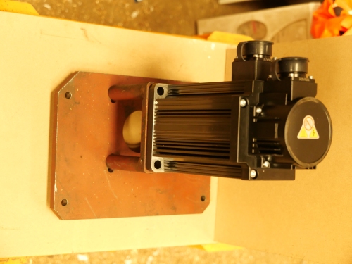
johnsmachines

machines which I have made, am making, or intend to make, and some other stuff. If you find this site interesting, please leave a comment. I read every comment and respond to most. n.b. There is a list of my first 800 posts in my post of 17 June 2021, titled "800 Posts"

Category: CNC MILL

Trunnion Mounts -3

I did not expect these mounts to require a third day session, and they are still not finished!

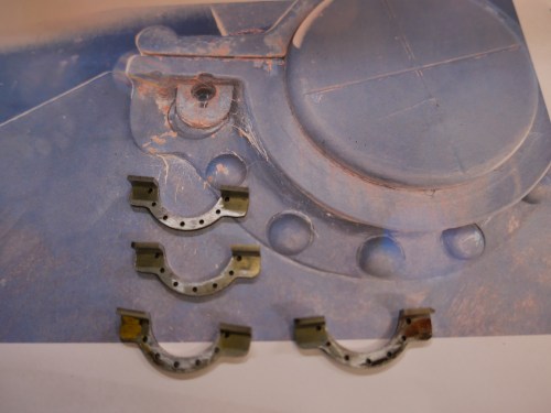
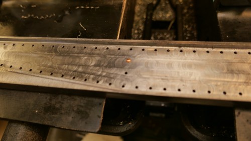
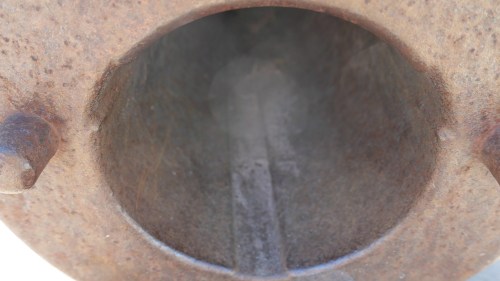
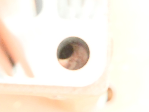
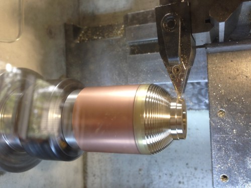
I discovered that two of the drilled holes in each bracket were in the wrong position, by approx 1mm.  That is a really bothersome error, because the correct position includes half of the existing hole.

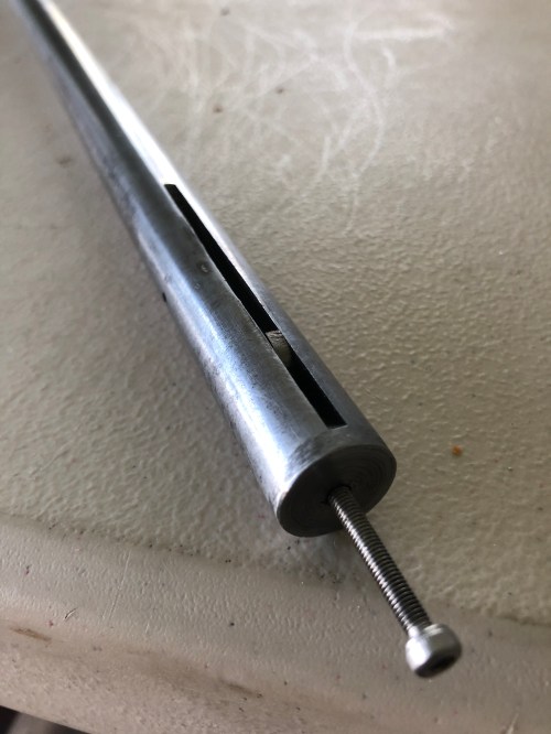
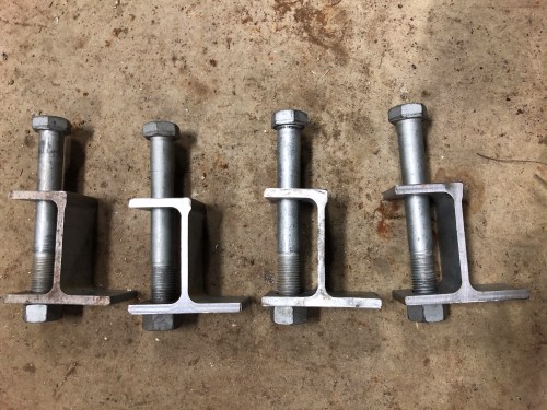
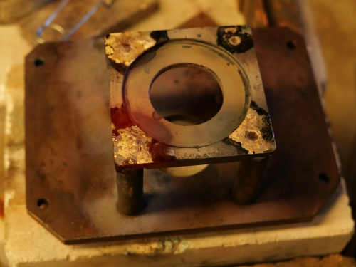
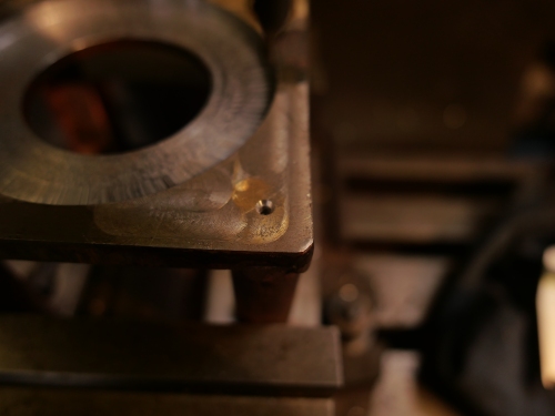
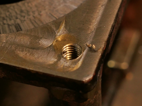
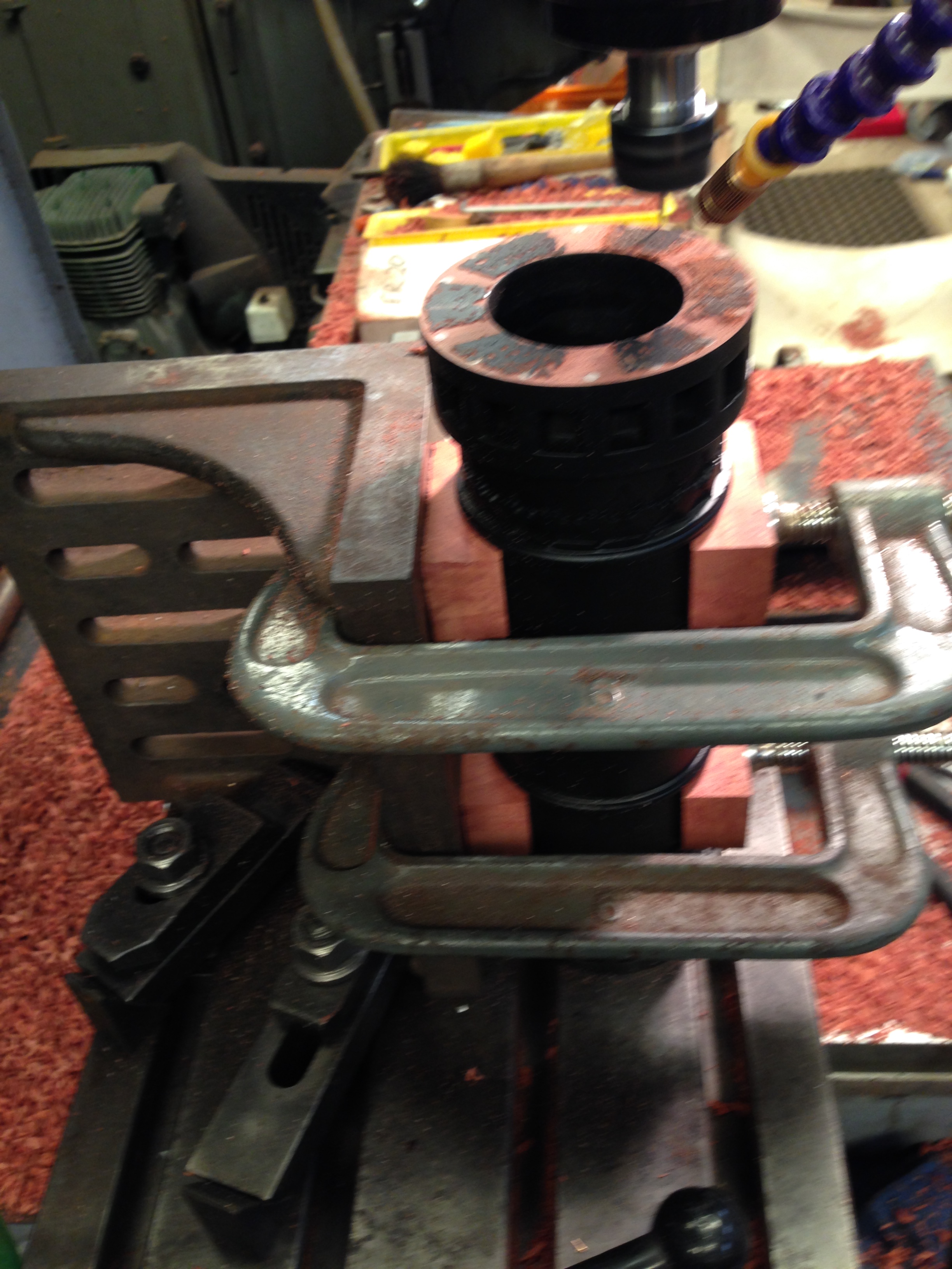
I managed the problem by threading the errant holes, and Loctite gluing in some threaded rod.  Each rod was trimmed flush with the surfaces.   Then drilling the new hole, partly through the Loctited metal patch.  That fix worked well.

P1074281

Threaded rod glued into the errant hole.  Trimmed flush later.  Then redrilled correctly.
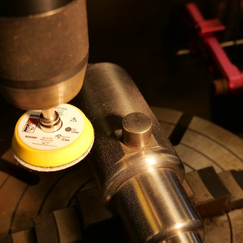
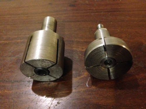
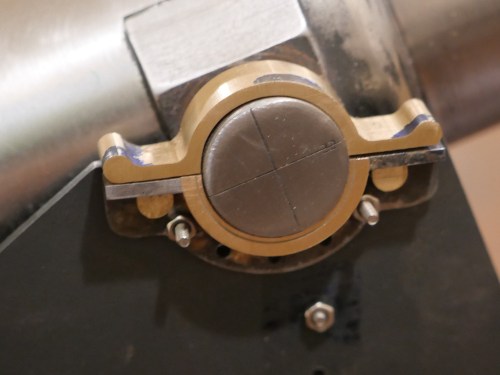
 

THE TRUNNION PINS.

The pins hold the trunnion caps in place.  And they took another whole day to make and install.   Ah….  just as well I enjoy all of this.  They are tiny, and I spent at least 50% of the time looking for them on the workshop floor after accidentally dropping them on several occasions.

P1074299

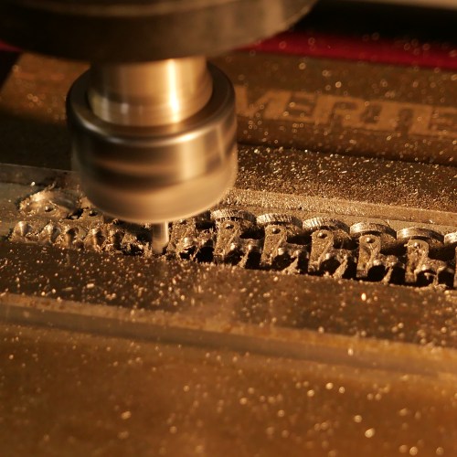
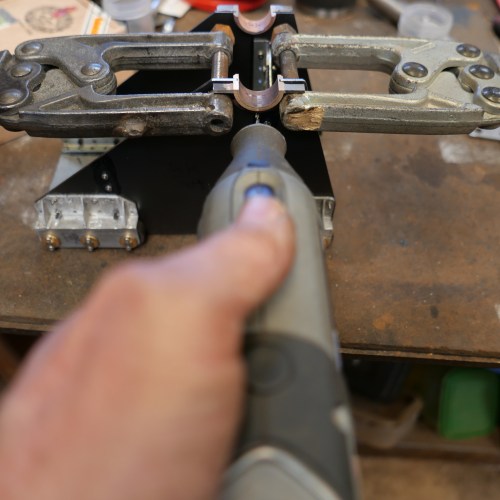
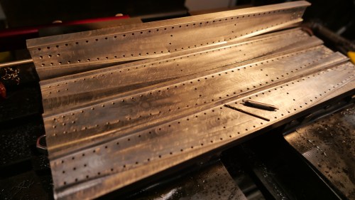
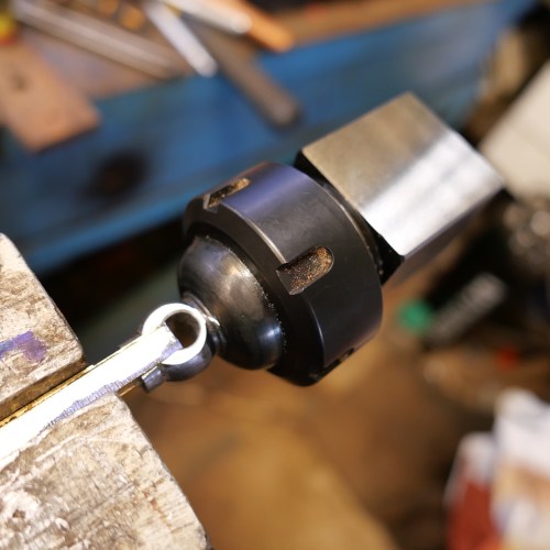
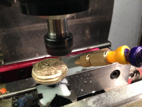
Milling the pin handles from 2mm steel.  The handles ended up at 7mm long.  The holes were drilled before the outlines were cut.  Then the tabs were ground off using my newly made belt sander belt.  The belt lasted 15 minutes before the belt itself tore, with the join still intact!

P1074308

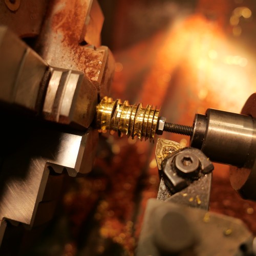
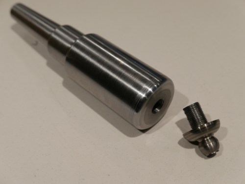
Then some delicate silver soldering of a ring to attach a securing chain later, then the pin shaft itself.  The wire through the ring is just to hold it in position during soldering.

P1074309

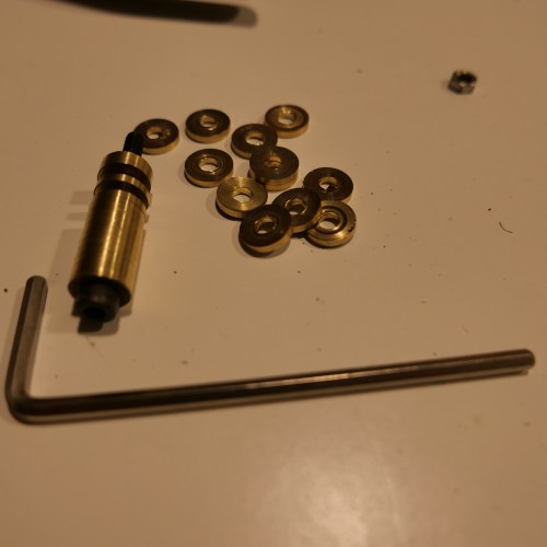
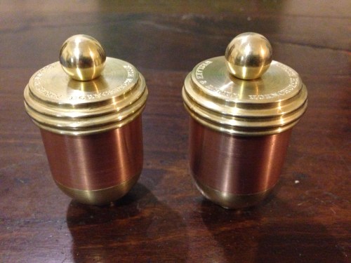
And that is one of the 8 pins made.  I will polish them in a gemstone tumbler next session.

P1074310

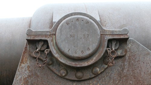
On the model, the pins are jammed into position with a cam action, after some filing-shaping.  On the original cannon there was a small protrusion on the inner end of the pin shaft, which fitted through a slot in the side of the carriage.  I could not figure out a method of making such a tiny slot (1mm wide x 1mm deep) through 4mm of steel plus 2mm of brass, but the cam action seems effective.    I will attach some chain soon, because I do not wish to make any more of these.  And yes, the pins handles are slightly over-scaled, but I think not outlandishly so.

So, apart from polishing riveting and painting, I think that the trunnion mounts are finished.

Now planning to make the gear train for the carriage positioning on the chassis, and the pinion, quadrant gear, and bevel gears for the barrel elevation.  We are currently in level 3 lockdown for Covid containment, with level 4 looking likely any day, so obtaining brass for the biggest gears is difficult.  I am considering workarounds.  Apparently community anxiety and depression, family violence, and even suicides are mounting.  When I am in the workshop I am in a different world, thank goodness.


Trunnion Mounts -2

It took a whole day making and fitting  the top caps of the trunnion mounts from brass.

P1074265

A 76 x 76mm piece of brass was milled to 10mm thickness.  The trunnion straps will finish at 9.5mm , giving me a 0.5mm machining allowance.

P1074269

The 4 straps were cut out using a new 4mm endmill.  Rounded internal corners were milled square, and the bottom tabs were milled to 2mm thickness.

P1074270

2mm wide slots were milled into the brackets, and ends of the slots were filed square.  None of my rifling files were small enough, so I ground one to size, leaving the faces and one edge  intact.

P1074276

Trunnion mount almost finished.  Pins in the tags to come, and they will pull the strap down tight with a cam action.  The half circle line on the bottom bearing is a painting border to delineate the bottom bracket from the bronze bearing surface which will not be painted.  If you inspect the full size trunnion in the previous post you will see what I mean.

P1074274

P1074273

Now I can take some measurements of the model, and start the barrel elevating gear.  There are 4 gears to be cut, including  bevel gears, handle, shafts, gear case, and some complex mounts.

Trunnion Mounts -1

On the Armstrong 80 lb RML model cannon, the trunnions are secured to the carriage with  steel brackets riveted to the carriage sides, and the trunnions rotate in a bronze bearing.

3404 trunnion L

The original trunnion on the Port Fairy cannon

P1074254

These are the component parts.

P1074238

The RSS ready for cutting out the brackets.  And my working drawing, with alterations.

P1074243

First the 2mm rivet holes were drilled, then the outlines were CNC milled.  The steel is 2mm thick.

P1074246
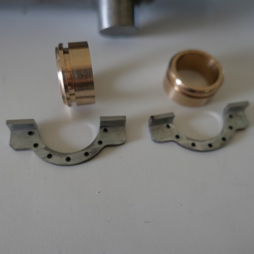
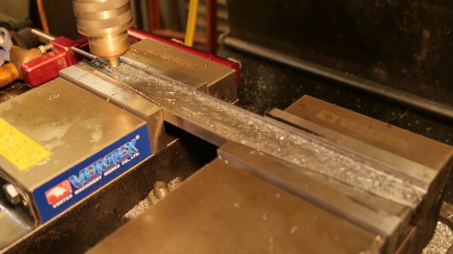
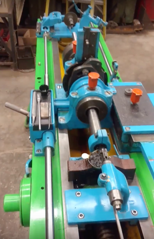
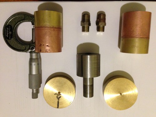
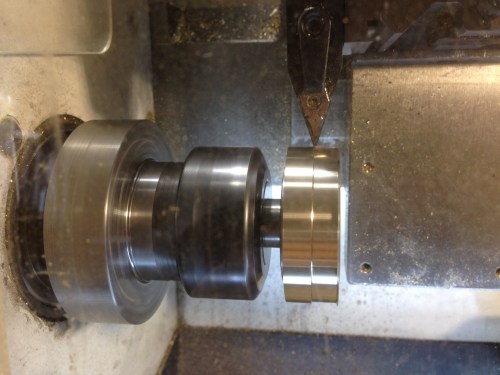
Tidied the parts with a file and belt sander.

P1074245

The brackets sitting on a photo of the original Warrnambool cannon.

The bronze bearing involved some basic lathe work.

P1074257

Then the components were silver soldered together.  Delicate work.  I did not want the solder running into some areas, and the join needed to retain a degree of precision.

P1074258

After cooling, sulphuric acid soak, and washing, the top half of the bearing was milled off.

P1074261

Some filing to make it fit the carriage, then rivet holes drilled with a Dremel while the bracket was clamped in position.

P1074264

Bolted in position temporarily.  Tomorrow I will make the top half of the bracket.  The gap between the bracket and the carriage caused by the metal folding will eventually be filled, and invisible.  A millimeter or so will be removed from the width of the bracket and bearing.

I had a bit of milling excitement while cutting out the steel components.   I was using a 6.35mm 4 flute carbide cutter, and when I started the program the machine plunged into the shape at extremely high speed.  When I checked, the feed speed was 60 times higher than I had specified.  Somehow, the units had changed from mm/minute, to mm/SECOND.  Amazingly, the cut was close to perfect with no damage to the workpiece.  But, alas, it wrecked the carbide cutter.

I had recently upgraded the CNC software (Vectric V-Carve Pro) from version 10 to 10.5.  Maybe some of my settings in the program had been changed in the upgrade?  I never use mm/second.  That is a woodworking CNC router unit.

Using a Banggood tool to make spacers

I needed 20 spacers, 2mm thick, 13mm OD, 5mm ID, to finish the carriage axles for the Armstrong model 80pounder RML.

I could have turned some 13mm OD, drilled a 5mm hole, and parted off the spacers in my lathe, but I know from experience, that the pieces never end up exactly the same thickness (in this case, 2mm thick).

So I decided to try a Banggood tool which has sat unused since I bought it many months ago.

P1074227

It is a HSS hole cutter.  18mm OD, but the disk removed is 14mm OD, just a bit bigger than I wanted.  2mm thick waste brass plate.

So I cut off 25 disks, from a piece of waste brass, 2mm thick.  The Banggood tool worked well, except that it need swarf picked out after almost every disk.   But it was quick, reasonably accurate, and the central drill bit was 5mm, just what I wanted.

P1074231

The disks were slid onto a 5mm capscrew bolt, and nutted down hard.

P1074232

The head of the capscrew was held in the lathe chuck, and the tail of the threaded end in a shop made tapered tailstock socket.  And turned to 13mm diameter. 

P1074234

About 12 spacers made per run.   Very quickly.  Reasonably accurately.  A bit of tidying to follow.

The Banggood tool worked pretty well.  I will buy some more of these.  They were quite inexpensive.

Today I polished the ends of the trunnions, being careful not to remove the lasered lines and markings.  I used a 200grit sanding pad in a sponge backed sanding disk in my milling machine.   Also worked very well.  I removed about 0.1mm of steel, without destroying the markings.

P1074221

91 x 4 drilled holes. Yes, counting.

Today I drilled the girders of the chassis under the Armstrong cannon.  Each girder has 91 rivet holes.  Later I will need to drill more for the gear shafts, and for the center pivot bar.

The holes are 2mm diameter.

PANA3767

The mill drill setup. Re- indicating the vices again took me about 45″.

PANA3769

Firstly all of the holes were center drilled, then drilled through.  The rivet confirmed a nice sliding fit.

PANA3770

364 holes, through 5mm of steel done with one center drill, and one 2mm drill.  That is pretty impressive IMO.  More than 1.8 meters of steel with 2 drill bits.  And using my olive oil and kerosene lubricant-coolant.   And the bits still seem to be sharp.

Each girder took about 28″ to drill the 91 holes.   CNC of course.  It has been a while since I said it….. “I love CNC”.


Rifling the Model Armstrong RML

P1053702

The HSS cutter is mounted in a tight 3mm wide slot in 16mm silver steel.  The 4 mm cap screw pushes the cutter up by 0.2mm per full turn of the screw.

The following video shows an air cut of the rifling cutter in the CNC rotary table on the CNC mill table.   Then some actual cuts in a 1:10 scale cannon barrel.  This barrel was a reject, and was used to practice the rifling cuts.

You can click on the arrow in the box below, or see the video full screen in YouTube.


Bronze Casting -2

When I looked closely at the rifling cutters which I had lasered out of a broken Brobo saw blade, I realised that I had boobooed.  I had measured the thickness of the blade at 2.5mm, which was actually a bit thinner than I wanted, but would have been acceptable. But when I measured the cutters, they were only 2.2mm thick.   Reason?  The saw blade had been hollow ground, and the blade inside the teeth was thinner.   Too thin, I decided.

So after some wailing and teeth gnashing I have ordered some 3mm thick tool steel in the form of planer blades, which I am pretty sure will not be hollow ground, and I will ask the laser cutter to cut me some more blades.  So waiting waiting.

And I am setting up the cannon barrel for rifling.  The CNC rotary table (stepper motor hidden behind) will be bolted to the CNC mill table.  The barrel is held in the jig which is held by the mill quill.  The cutter, (not seen in this photo) will be drawn out of the barrel by the mill X axis, while being rotated in the A axis by the rotary table.   That is the plan anyway.  But still waiting for bits to arrive so I can finish the cutting tool.

P1053658

The Armstrong cannon barrel held to the mill quill, and the rifling cutter will be held by the CNC rotary table.

IMG_8537

The rifling tool which I will not be using because the cutter is too narrow.  The cutting edge just peeping out of the slot will be dragged and twisted through the barrel bore.  The cap screw adjusts the degree of protrusion.


BRONZE CASTING

Meanwhile, I am accumulating various bits of gear to do some bronze casting.   An electric furnace with graphite crucible from China, Some jewellery investment material for the moulds, and a second hand pottery kiln for preparation of the moulds, and melting out the PLA 3D printed parts.   I will take some photos when it is all here.

And SWMBO has conscripted me to assemble and install some kitchen cupboards for a property which she is renovating.

P1053684

P1053685

These are flat pack units.  Kaboodle.  Well designed and CNC cut and predrilled.  Not quite finished.  Waiting for the stone bench tops to be made and installed, and for appliances to be wired and plumbed.  Frankly I would prefer to be tidying up my workshop, but hopefully I am gaining some “Brownie Points”.

Model Cannon Barrel. (T)rifling Thoughts.

My aim (as it were) in making this model cannon is to have a high visual quality exhibition piece.

It is a 1:10 scale model, 1866 Armstrong 80lb, rifled muzzle loader, blackpowder cannon.

One question which always arises is whether it will be actually fired.  My answer is that if it could be fired legally, it would be nice so I could make a video.  However, Australia has very strict gun control laws, (with which I totally agree), and I do not intend to flout those laws.  So this gun will not be capable of being fired.  It will have no touch hole.

To satisfy the visual appearance of a touch hole there will be a laser printed dot at the location.  Along with laser engraved Queen Victoria insignia, sight lines, etc.

But, it IS a rifled cannon, so I do intend to rifle the barrel.  And that needs to accomplished before the trunnions are fitted, and after the cascabel is fitted, so the orientation of the rifling is as per the original.

P1053354

The original rifling.  The 3 grooves are each 30mm wide, (clockwise or anticlockwise, not sure) and extend up to the edge of the powder chamber.  They are about 2 mm deep.  The powder chamber is slightly wider than the barrel bore, being continuous with the depth of the rifling grooves.  It is academic, because it will not be visible, but I will make it (the powder chamber, and the whole model) as accurately as I can, for my own satisfaction.  Fortunately the powder chamber is accessible to machining from the breech end, because the cascabel is screwed into position, and is removable.

Yesterday I started making the cascabel.  It was difficult.  The steel thread is lathe cut first, then the shape is lathe CNC’d.  Then there is milling the insides, and making a removable pinned rope retainer.  The third attempt was the most successful, but I am still not satisfied, and so there will be another one made today.   This is what I have so far…

P1053635

The turned barrel, threaded to accept the cascabel.  More work is required on the cascabel.

P1053642

The cascabel is mounted in an ER40 chuck.  It has been drilled and milled, and a removable insert is temporarily glued into place pending more machining.


Rifling.  Searching YouTube reveals multiple tools and setups from US sites.  Here are a few screen shots to show you some varieties.

From the sublime ….

Screen Shot 2020-02-16 at 8.29.10 am

to the other extreme…

Screen Shot 2020-02-16 at 8.39.12 am

No.  I will not be using a PVC pipe lash up.

The amateur designed and built machines are interesting….

Screen Shot 2020-02-15 at 9.15.27 am

Sine bar on the right.

Screen Shot 2020-02-16 at 8.23.12 am

Screen Shot 2020-02-16 at 8.24.24 am

Then there is the method of pressing a button cutter through the bore.  My bore is an odd size, so if I used this method I would need to make my own cutter.

Screen Shot 2020-02-16 at 8.36.35 am

Screen Shot 2020-02-16 at 8.29.57 am

This one is a computer animation of a 19th century rifling machine, now a museum exhibit.   Can you see the barrel?   Armstrong probably used a much larger version of this type to rifle his cannons.


But I think that I will use none of these methods.  I have a CNC mill and a CNC rotary table.  Mach3 can control both of these machines simultaneously.   If I mount the cutter assembly in the rotary table, and the cannon barrel to the mill quill, I should be able to cut the rifling grooves.  Still working on this one.

CNC Mill Upgrade -8

Fitted the new VSD Friday.  Ordered Tues pm.  Arrived Thurs am.  Impressive.

$AUD315, inc shipping.   Job cost is mounting.  Still within reasonable limits.

P1032876

The old VSD, top right.  The axis controllers (top left) had not been wired when this photo was taken.

IMG_8151.JPG

The new VSD (variable speed drive) 4kw.  Fitted neatly with some new mounting holes, without any drama.  The rats nest looks less daunting every day.

Now, except for the main spindle motor, there are no more original major electrical components.  All have been updated and replaced, along with the cables.

Yet to be wired are the VSD, coolant pump, oil feed pump, limit switches, homing switches, and the Gecko driver and 48v power supply for the rotary table.   But the mill is useable now.   Video coming up soon.


CNC Mill Upgrade – 7.

2 steps forward, 1 step back.   That’s what this project is experiencing.

The axis servo motors, their controllers and connections to power, breakout boards, and computer connections are complete, and all working.

An old laptop has found a use.  Installed Mach3, Vectric V-Carve Pro.   And the connections to the Smooth Stepper board.  Windows 10.   Deleted all non CNC related programs to gain space on the hard drive.

A problem with the main spindle.  It is essentially unchanged from the original.  Same motor (4kw/5hp 3 phase), same VSD, and same 3 phase power which is supplied through a phase changer, because the property has only 2 phases supplied.  When powered up, it worked, but the RPM’s could not be altered from a very slow rate.  The controlling voltage from the breakout board was not changing despite changing the inputs.  ? due to a problem with the settings, or a faulty BOB.  Didn’t seem serious.

So I was a bit surprised when later I switched on the mill, intending to change some settings, to hear 2 significant pops, and to smell that disgusting burnt electrical component smell, with smoke coming from the electrical enclosure.

Quickly shut everything down, and waited for the cavalry to arrive.

Stuart found that a 24v power supply had failed.  No big deal.  Not an expensive component.  Maybe got a short circuit from a bit of swarf?   But further inspection revealed that the VSD had also failed.  A capacitor and diode burnt out.  ? caused by a surge from the failing power supply? Repairable, but I decided to buy a new VSD.  The failed VSD is probably as old as the mill (24 years), so it had a pretty good run.  If the old VSD is repairable, it will serve as a spare.

Meanwhile, as a consequence, the main spindle is not working.  I have a list of jobs that I want to get into, particularly the steam pump for the vertical boiler.   So I will reattach the high speed spindle and use that.  It is 2.2kw, but uses high revs to develop power, so I will be limited to small end mills and drills, until the new components (VSD and power supply) arrive.  The high speed spindle is single phase, and the speed control is manually selected.   Not quite as convenient but useable for the time being.

While Stuart has his head buried in the electrical enclosure, I have been his gopher and TA.  But also fitting in a couple of other jobs which have been on the “to do” list for ages.  Like clearing out rubbish from the workshop, tidying up etc.

One task which has been vexing me, was to remove a sheet of flooring board which was under the Colchester lathe.  The sheet was originally placed under the lathe to protect the vinyl floor covering, but it was not a good decision.  As the flooring board became wet with cutting oil and coolant, it would swell and shrink, and I was aware that the lathe levels and settings were changing.  So I decided to remove the sheet of flooring, and let the lathe feet sit directly on steel pads on the vinyl/concrete floor.

But how to remove the sheet of flooring from underneath the almost 1 ton lathe?  The lathe was originally placed into its rather tight position with a forklift, which is no longer available.  The wooden sheet was the same size as the base of the lathe.

So I made these…

img_8146.jpg

The bolt adjusts the height of the jack.

IMG_8142.JPG

From a piece of scrap I-beam.

I used a crow bar to raise the corners of the lathe enough to place the jacks into position.  A bit of trial and error to get the heights correct.    When the lathe was about 25mm clear of the flooring, I pulled the sheet out.  Then used the crowbar to remove the jacks, and lower the lathe onto its base plates.

I will reset the lathe’s screw feet in the next day or 2, using a precision level and test cuts.  There was an excellent YouTube video by “This Old Tony” on the subject recently.


CNC Mill Upgrade – 6. Where to put the computer?

Not much more to report today, but I have decided how to position the computer.

Not easy, because the computer needs to be protected from flying swarf and coolant spray from the CNC mill and the manual mill which is immediately adjacent.    And I want the computer to be close to the machine.  The CNC mill is NOT in an enclosure.

So this is what I have decided….

IMG_8128.JPG

The laptop is just low enough to reach while standing.   The E stop and other buttons are underneath.

And if the swarf is really flying, I can turn the PC away…

IMG_8129.JPG

Might need some adjustments.  The laptop is an old Dell ATG.   Said to be resistant to fluids and relatively resistant to shock/vibration etc.   Military specs.   I might add some side protection and perhaps a roof.


CNC Mill Upgrade -5

I have been putting quite a few hours into the upgrade, but not much to show photographically.

Finally got the new servo motors installed.  Replaced the X axis belt.  The most difficult servo to access was the Y axis, and of course that was the only one where the alignment of the timing belt was out.   Finally sorted by using a fibre optic camera to see why the belt was climbing onto the flange of the pulley.  The pulley was 1.2mm too far onto its shaft.  I know that, because I solved the problem by inserting washers under the motor mounts.  1mm washers did not work, nor did 1.5mm washers.  But 1.2mm washes did work perfectly.

Today Stuart arrived and removed more of the old wiring.

P1032880.JPG

Stuart, doing another CNC upgrade wiring.

P1032881.JPG

The old 7k computer has been removed, leaving some buttons.  I might be able to use those. The computer enclosure might disappear too.  Not decided yet.

P1032882.JPG

The old CNC mill has lost some weight.  Those cartons are full of old parts.  Note that the floor has been swept.  Stuart was concerned that we might be infested with snakes, but it is winter here, so we should OK until the weather warms up.

P1032883.JPG

The rats nest is disappearing.

CNC Mill Upgrade -4

I removed the old XY & Z axis servo motors from the mill.  Each one weighs about 15kg (33lb).

IMG_8119.JPG

The old servo motors.  The X and Z were working fine.  The Y was faulty, but I do not know whether the fault was in the motor, the encoder, the controller, or the connecting wires.  I will put them on Ebay as 2 working, one for parts.

Then I removed the belt drive pulley off each motor.  There was a grub screw, which would not budge.  Assuming that it had been Loctited, I applied some heat, judiciously.  The grub screw came out, but the pulley would not budge, so a little more heat, and a gear puller.   Two of the gears came off, but one still would not budge.

I asked for advice, and I was loaned a different type of gear puller. (thanks Rudi).  This time, some movement of the gear on the shaft was noted, and eventually the last motor gave up its gear.

img_8122.jpg

This one worked.

The shaft of the old motors was 16mm diameter.  The new motors had 19mm shafts.  So I spent some time on the lathe boring out the gears to fit the shafts of the new motors.  The keyways of the old motors were 5x5mm, and the new ones were 6x6mm.  So, I borrowed a 6mm broach (thanks Stuart), and enlarged the keyways in the rebored gears to 6mm width.   The new keyways needed a lower profile, so some time on the mill and surface grinder  to reduce the thickness of the keys to 4.5mm.

That was quite a few peasant hours hours on the lathe, mill, and surface grinder, but the end result was good.

P1032877.JPG

The new servo motors, with the timing belt gears fitted, with keys in place.  I will set each motor in place on the CNC mill, determine the final exact position of the gear on the shaft, then indent the shaft for the grub screw.  Then, when I am sure that all is correct, the gear, grubscrew and shaft will be Loctited.

Another small issue was that the boss on the new motors was 5mm deep compared to 3.5mm deep for the originals.  So the mounting plate for each motor needed the recess to be deepened by about 1.5mm.

P1032878.JPG

I used a boring head on the mill to deepen the first one, but it did not produce a good finish, so the next 2 (shown) were deepened on the lathe, in a 4 jaw chuck.

Meanwhile, back to the rats nest in the electric control enclosure….


P1032875

The bare space top left is where the old servo controllers lived.  They were removed.  Then I spent a half day tracing each wire from the controller to the old servo, and removing it.  That produced a carton full of wires.  The rats nest is now a little less tangled.  A lot more of those wires will be removed as the job progresses.

P1032879.JPG

The new servo controllers bolted into position.  They are fatter than the originals, so a bit of rearranging was required.  The yellow box top right is the main spindle speed control (VSD) which is being retained.

P1032876.JPG

And on the right hand side, newly bolted into position today, from the top down, are the smooth stepper, the C11 breakout board, and two C10 breakout boards.   Awaiting some expert wiring.  (Stuart, are you reading this?)


Upgrading the CNC mill -3. Moving a threaded hole in steel plate.

P1032869.JPG

this is the new Y axis servo motor, sitting on its mounting plate, after the old servo has been removed

P1032863.JPG

Unfortunately the existing M8 threaded holes in the mounting plate are just in the wrong position for the new motor’s 8mm mounting holes.

So, do I 1. make a new mounting plate and assembly?   2. machine or file the new motor’s holes to fit the old plate?   Or 3. Fill the old mounting plate hole, then drill and tap new holes in the correct position  ??

  1.  seemed a lot of work   2. would have looked ugly and probably voided the motor’s warranty      3.  Seemed tricky, but I decided to give it a go.   If unsuccessful I could always revert to 1.

Filling the old holes.  Could have used steel thread and silver soldered it into place.  In retrospect, would probably have been the best option.   Could have used steel thread and Loctited it into place…. decided against, in case subsequent machining  softened the Loctite.   Could have filled the old holes with bronze, and drilled and tapped new threaded holes….   well, for better or worse, that’s what I decided to do.

The new holes impinged about 25-33% on the old holes.

P1032870.JPG

The old holes were bronzed.   I improved my technique as I moved around the holes.

P1032871.JPG

After cleaning up on the mill, the new holes were center drilled 

P1032872.JPG

Then drilled to size, and tapped.  revealed that the bronze did not entirely fill the voids. 

P1032874.JPG

I wondered if the bronze would accept a suitable degree of tightening of the M8 cap screws, but all seemed fine.   Note the jacking bolts, to prevent distortion of the weldment in the milling vice.

The bronze-steel sandwich did cause the tapping drill to wander slightly, but not enough to cause concern.  Next time I will try silver soldering in a steel filler piece.

Meanwhile, I have been removing parts and wires from the electrical enclosure.

P1032875.JPG

The servo controllers are removed.  Bit of a rats’ nest hey!  About 90% to go…


CNC Mill Upgrade -2

The major components arrived this week, from China and USA.  Switches, and other components which go “ping” will be bought locally as required.  I am hoping that existing pulleys, belts, brackets will be adaptable.

The motors to drive the X, Y and Z axes are 1.2kW AC servo motors which can be connected to single or 3 phase power.  Each one weighs 6.7kg (14.7lb) .  From China, they are nicely finished.   Substantially shorter than the old servos which they are replacing and slightly larger diameter.  I am hoping that the slightly larger diameter will not cause major problems.

IMG_8088.JPG

AC servo.  There are 3 of these.  Kitchen knife to open the box and for scale.

IMG_8115.JPG

Old Y axis servo on the right, and the new AC servo left.


And each servo motor came with a controller and cables and connectors.

IMG_8093.JPG

And the electronics came from USA.

img_8096.jpg

C11 breakout board.

img_8097.jpg

C10 breakout boards x2

img_8098.jpg

And the Smooth stepper control board.  It is tiny, but the most expensive electronic component.

All up cost so far is ~$AUD2100, of which shipping is about 25%.

Next step is to swap over the servos.  The old shafts are 16mm and the new ones are 19mm.  I intend to machine the bores of the pulleys.  Hope there is enough meat  Tofu to allow that.

CNC Mill Upgrade

I was not planning any more major projects for 2019, instead intending to finish the triple expansion engine, the beam engine, the vertical boiler, and the CNC rotary table.

But… my hand has been forced.

The Y axis on my CNC mill has been a bit unpredictable for some months, and on my return from UK, it has totally stopped working.  It seems to be the encoder on the Y axis servo.  I could just repair or replace the encoder, but after discussing the situation with my expert advisor Stuart, I have decided to replace all of the electronics in the mill.  New axis motors, new breakout board, new drivers etc.  It is a 1997 model, and this is the second electronic failure this year.  Plus, it is only a 2.5 axis mill.  It will move in only 2 directions per move….   XY or XZ or YZ,  never XYZ in a single move.   Plus I would like to add a rotary axis, making it a 4 axis machine.

The in built computer in the mill has a 7k memory.  That’s correct, 7000 bits.  I have an external computer linked to it, which makes it a bit more useful, but the Fagor controller is clunky and idiosyncratic, and I would like to switch to Mach 3.

So, I will document the upgrade as it happens.  The mill is a good solid machine, with big ball screws, and 1000mm of x travel, 450mm Z and 450mm Y.  It is worth spending some money on it.  There are a lot of big, old, CNC machines with obsolete electronics out there for sale.  It will be a project which might just be worth watching.

Showing the handwheels for XYZ axis movements, including the broken X axis handwheel


Turkish Bombard. The Barrel Script

Well, I bought a pair of NSK bearings for the Z axis of my CNC mill, and removed the old ones and inserted the new ones.  Cost $AUD 200.  Plus 2 or 3 half  days of  dirty heavy work.    And the problem persisted!!@!@

OK.  Time to get an expert opinion.  Here comes the cavalry.  Thank goodness for my expert friend Stuart T.

Very puzzling.  Even for Stuart.  There was some unwanted movement in the Z axis (about 2mm), despite being apparently properly installed.  Not a problem with the ballscrew or ballnut.  Even Stuart was puzzled.

“have you got any left over bits and pieces?  Is it all installed the way it was before?”

To cut the story short, we installed a thicker washer below the locknuts, and it seemed the problem was fixed.  Or was it?

Today I did another test run of the bombard mouth Arabic script.  Worked fine.  OK.  Time to finish the bombard.

IMG_4559.JPG

Here is the finished result, ready for painting.  I have used a 20 degree engraving carbide bit with a 0.2mm flat end.  There is some loss of fine detail but it is I think, adequate.  When it is painted, the filling putty above the pin screws (the white circles) will be invisible.  The engraving took a total of about 60 minutes, at 500mm/minute, 15,000 rpm.

IMG_4554.JPG

The setup.   A large angle plate clamped to the table.  The work clamped to the angle plate.

The translation of the Arabic script is “Help O God the Sultan Mehmet Khan son of Murad. The work of Munir Ali in the month of Rejeb. In the year 868.”

Modelling a Turkish Bombard -4 Decoration

The decoration around the barrel is formed by a repeating pattern, which when milled, very cleverly forms 2 identical patterns.  One is excavated and one is the original barrel surface.  You will see what I mean if you look at the pictures in the earlier blog, and the video below.

It took me an evening of experimenting on the computer to work out the system and draw it.

bombard-pattern3

Then I measured the diameters of the 2 gun components, calculated the circumference, (OK it is not rocket science.   3.142 times diameter), then working out the number of identical shapes which would fit around the 2 different diameters, at the same size and spacing.   Amazingly, it took 18 shapes to fit almost exactly around the barrel, and 16 of identical size almost exactly around the breech.  the angular spacing was 20 degrees and 22.5 degrees.

Then the shape was imported into V-Carve Pro, and G codes were generated.

My CNC mill does not have a 4th axis, so I used a dividing head to move the workpiece at the precise angles.  See the setup in the video.  That meant that the pattern was engraved into 16 and 18 flat surfaces, rather than a continuous cylinder as on the original.

It worked very well.  There were minor compromises due to the shapes being milled with a fine end mill but when you look at the pics I hope that you will agree that it is effective.

I calculated that the milling had to be at a maximum depth of 2mm in order to cope with the curvature, but if I do it again,  I would reduce the depth by 25%.

The first part of the video is a shot of CNC drilling.  Then the CNC routing of the repeating patterns.  Each angular setting of the pattern took 4 minutes to complete.  136 minutes altogether.  In reality, it took a whole day, most of which was spent doing the setups.


Steam Engine Oilers

Knowing that I have an interest in CNC machining, Tom, from the Vintage Machinery Club in Geelong asked me to make a pair of oilers for a very old Wedlake and Dendy steam engine.  The engine is a large (to me anyway) stationary engine, which is run on steam several times each year.  The oilers for the cross slides were missing.

We searched the Internet for pictures of W&D steam engines, but could find no pictures or diagrams of the oilers.  So Tom sketched a design, and I drew a CAD diagram.  The dimensions were finally determined by the materials which I had available…  some 1.5″ brass rod and some 1.5″ copper tube.

This is the almost finished product.

IMG_4250.JPG

Just needs 1/4″ BSPT fittings and and oil wick tube so they can be fitted to the engine.

IMG_4222.JPG

The copper tube silver soldered to the brass cylinders (top), the brass blanks for the lids (bottom) and the mandrel to hold the assembly (bottom centre) during CNC turning and drilling.

IMG_4246.JPG

The mandrel to hold the body (left) and the mandrel for the lid (right).  The cap screw head and hole in the mandrel have a 2 degree taper.  The slits were cut with a 1mm thick friction blade.

IMG_4243.JPG

Rough turning the base.

IMG_4231.JPG

Turning the lid.  The mandrel is held in an ER32 collet chuck

IMG_4245.JPG

Engraving the lid.  Using a mister for cooling and lubrication.  16000rpm, 200mm/min, 90 degree TC engraving cutter.

IMG_4251.JPG

The oilers work by wicking the oil from the reservoir into a tube which drains through the base onto the engine slide.  When the wick tubes are fitted the oilers can be fitted to the engine.

IMG_3196.JPG

The 1865 Wedlake and Dendy

IMG_3195.JPG

1865

My lathe is a Boxford TCL125, using Mach3.  The G code is generated using Ezilathe.

Below is a link to an oil cup from “USS Monitor”, of American civil war fame.   One of the first ironclads, powered only by steam.

http://www.marinersmuseum.org/blog/2010/04/one-oil-cup-down/

(ps. The  lathe which I was converting to CNC was the subject of previous posts and is now working, but needs some guards fitted and a bit of fine tuning.)

COMPRESSED AIR ON THE CNC MILL

Compressed air is very, very useful on the milling machine.  The tool changer uses air for fast tightening and release.  And I often use air to clear the field of swarf, and shavings (yes, I use my mill for wood  too).

Recently, at the suggestion of Stuart L  of stusshed.com fame, I installed 2 semipermanent nozzles on the mill, with adjustable direction and pressure adjustments.  It has been a quantum leap improvement.

carronade - 1.jpg

The pic shows the jets aimed during CNC end milling of wood.  The wood shavings are blown away which makes it easier to see how the milling is progressing; blows them away from me which is safer and cleaner; and stops the chips being machined into the work, which leads to a cleaner cut.  It also improves any video or photo of the progress.  It must also cool the cutter, although not as effectively as a liquid coolant.  I have not tried using the misting attachment, which would improve the cooling, but at the cost of dampening the area and the work.

I particularly like the improvement experienced when machining brass or steel.  The swarf is removed from the advancing cutter, preventing it being re-machined and squashed into the workpiece.  I am noticing better surface finishes.  I also adjust the air direction to keep the swarf away from me;  particularly valuable when brass needles otherwise would be flying at me.

When cutting pockets, the air keeps the pocket free of swarf, and when using tiny endmills at high speeds I am experiencing fewer tool breakages.

This gadget was inexpensive ($AUD12) from China.  It does not work the compressor too hard when the volume is turned back as far as possible, but still adequate.  Although there are 2 jets, I find that only one at a time is adequate.

Recommended.

As an afterthought.   I rarely use coolant on my lathes, but an air stream on the cutter and workpiece would probably have similar advantages to those listed above.  I particularly wonder if it would assist during deep parting…   always a tense procedure.  I suspect that the cutter becomes hotter and expands more than the workpiece parting slot if there is no coolant.  I will mention the result of air cooling and chip clearing on the lathe in a later blog.

Problem with Balls (Incarcerated ball bearing)

The X axis on my NC mill was always noisy in operation from the time I purchased the machine a year ago, and the seller told me that he thought the end bearing was the source of the noise.

In comparison, the Y and Z axes were almost silent in operation, swishing to their allocated positions.

But the machine worked well and accurately, so I did not fuss about the noise.

But a couple of weeks ago, the X axis low pitched rumble changed to a louder, more graunchy sound, which I did not like at all. However the accuracy was still not affected.  And the noise occurred only with rapid feeds.  On machining feeds, it was not noticeable.

So, with some trepidation, and only a vague notion of the construction of the machine, I disassembled the suspect bearing.  That involved unscrewing covers, unbolting the heavy servo motor and lifting it to the floor (not wise.  my back still aches.  next time I will use a supporting jack or platform), then trying to figure how to remove the toothed pulley.  A phone call and text message including photo to my expert friend (thanks Stuart) gave me the necessary information how to remove the tapered bush and pulley.  I made a simple gear puller which screwed into 2 threaded holes in the end of the tapered bush, and the whole lot magically came apart.

The bearing housing, toothed gear and tapered bush.

The bearing housing, toothed pulley and tapered bush.

Removed the toothed belt.

The bearing housing was next, secured by 5 large cap screws.  But it would not budge, despite removal of the screws.  The 2 locating pins were tightly ensconced, and persuasion was required with a series of slim wedges, hammered into the gap.

I took the cleaned up housing containing the bearing to Bob Hamilton’s Bearings and the expert there explained that there were actually 2 bearings pressed into the housing.  These were angular bearings, facing each other.   I thought that he would be able to tell me if they needed to be replaced, by the feel of them.  Unfortunately, he explained, the only way of knowing for sure, is to actually replace them, and see if the problem is fixed.

The replacement bearings would have to be ordered at a cost of $au100, but should be delivered within 24 hours.   Since my machine was out of action and of course I was in the middle of a job, I decided to insert the new bearings.

Sure enough, they arrived the next day.

A bit nervously, I pushed out the old bearings.  I made up a brass pusher to the size of the opening, and the bearings slid out fairly easily.  So far so good….

The reader should be mindful that a retired gynaecologist does not have a vast experience of changing machine bearings.

I carefully noted how the bearings were asymmetric, cleaned the cylindrical cavity and my hands, set up the press, and pushed the first bearing home.

No problem.

Except that the bearing was back to front!

Despite my careful noting of the configuration, I had managed to get it wrong.  Stupid stupid stupid.

And there was now no access to the outer race of the bearing to push it out!

What to do?

I have heard of using frozen carbon dioxide to shrink bearings and make removal easier.  But I have no idea how to access CO2.

The bearing slid in easily enough, so would it matter that much if I pushed on the inner race to get it out?

Oh well.   WTF.   If worse comes to worst I will fork out on another bearing.  But maybe with a separate supplier.  Just to save  much embarrassment.

So I pushed on the inner race.  It took more pressure than getting it inserted.   Then bang!

The inner race, the ball cage, and the balls, popped out.   I retrieved them all.  Fortunately the balls were sizeable and easily found.

But the outer race was still stuck in the housing, and what was worse, there was no edge to push it out.  Nor was there a gap at the housing base.  The race was still pushed firmly home.

F**k,  f**k, f**k.!!

CO2 option??   Same problem.  No idea how access it.

Drill some holes through the housing to allow access for a pin punch?   Ugly idea but might work.  Keep that one in reserve.  I really did not want to risk weakening the housing.  The machine is 18 years old and I am certain that such spare parts would not be available.

Maybe I could somehow lever the race to create a gap at the base and get it started.   But no access, and did not want to risk damaging the housing.

So, to cut this story short, I turned a steel disk about 5 mm thick, with a 25mm central hole,  and outside diameter just to fit into the housing through the race.  The disk had a knife edge.  I cut the disk, to enable it to be expanded.   Inserted it into the point of contact between the race and the housing, then expanded it using a pipe expander.  I could have used a tapered bolt, but the pipe expander worked.  As it expanded, it pushed into the slight groove between the race and the housing, then I felt the race move a little.  Some further expansion, and it moved some more.  Then, hallelujah, the race popped out. (I will insert some pics tomorrow).

The Pics.  (added 16 Sep 2015)

The pipe expander.

The tube expander.  Usually used for joining copper pipe.

The knife edge, split ring, used to dislodge the bearing race. (seen here in its expanded state.)

The knife edge, split ring, used to dislodge the bearing race. (seen here in its expanded state.)

Another view of the knife edge split ring, in its expanded state.

Another view of the knife edge split ring, in its expanded state.

On inspecting the angle contact bearing, I could see no marks or indentations on the bearing surfaces, or the balls.  So I cleaned the bits, reassembled the balls in the cage with clean grease, and pressed the assembly together in the press.  It all went together with a satisfying “click”.  It seemed to rotate smoothly, so I pushed the bearing back into the housing, then its partner, correctly this time.

After reassembly, I tested the machine.

It worked smoothly, and the X axis is now as silent as the other axes.

I feel stupid that I got the assembly wrong first time, but happy that it worked out in the end.  And a bit chuffed that the expanding, knife edged disk idea worked!  Probably reinventing the wheel.  Not happy about breaking apart then pressing together the bearing.  However if it becomes noisy again I will be more confident about replacing it.

I suspect that the original bearings were not actually worn, but just needed the securing nuts to be tightened.  If I had tightened the securing – compressing nuts, I might have solved the problem.  Oh well, live and learn.  I will keep the old bearings as spares.

24000 RPM spindle for CNC Mill 2

Yesterday the spindle was wired to the Variable Speed Drive – single to 3 phase converter, and to power. It span smoothly and quietly, and very fast.  Much quieter than a woodworking router of similar power and RPM.

Today I hooked up the coolant, after testing the pump.  But when I ran the coolant through the spindle, there was no movement of the coolant.  So I reversed the fluid connections in case it was direction specific, but still no action.

The pump and lines were OK, so there was a blockage in the spindle.

I removed the coolant connectors on the spindle, and I could see something white and foreign deep in the works.  A bit of poking around revealed that it was probably a bit of packaging foam.  I dug out some, then blasted the rest out with compressed air.  Testing with the compressed air showed that the way was now clear, so I reinserted the supplied fittings.

And one of them snapped level with the surface of the spindle cover.  Bugger bugger.

I managed to get the broken buried thread out of the spindle using an “Easy Out”.

The broken fitting looked complex.  I certainly did not want to wait for one from China, and I was very doubtful that it would be available locally.  I could have made one, but it looked like a half day job.

So I silver soldered it!

The top of the spindle.  The fittings, with the broken one on the left.

The top of the spindle. The fittings, with the broken one on the left.

The coolant fitting and its broken thread, fluxed and ready for silver soldering.

The fitting in position for silver soldering. Resting on a nail held in a vice.

IMG_2723

The fitting after silver soldering. The threads needed to be cleaned up by running a die down them

This is the setup during the first engraving job.

This is the setup during the first engraving job. The green fluid is the coolant.

Engraving a small brass plate, at 20000 rpm.

Engraving a small brass plate, at 20000 rpm.

24000 RPM spindle for CNC Mill

IMG_2718

The mill quill and spindle is on the right hand side, with a 1 inch cutter insitu. The high speed spindle and its VSD controller is on the left hand side. Of course the cutter on the rhs will be removed when an engraving cutter is installed in the high speed spindle. The wiring hook ups, and coolant pump and lines are yet to be installed It does not look much but it took me a whole day.  The setup is quite rigid.

Today I spent a few more hours setting up the high speed spindle on my CNC mill.

I will post a video when i am doing some label engraving.

Make Your Own LONG SERIES TAP

My current project is a diversion from the triple expansion steam engine, which is about 33% completed.

I wanted to do some engraving on my CNC milling machine.  It is accurate enough in XYZ movements, but the spindle has a maximum RPM of approximately only 3000.  Engraving with a cutter with a tip of diameter 0.1 to 1 mm diameter really requires 10-20 thousand RPM.

I also have in mind making some wooden things using router bits, and they usually rotate at 12-26 thousand RPM.

I wondered about a manufacturers attachment for my mill but could find nothing.

So I decided to make my own.

I briefly considered attaching an electric  router to the mill, but since many projects require constant spindle work for several hours at a stretch, I decided that the spindle should have an inbuilt cooling system.

What I bought was a 2.2kW spindle, 3 phase, with a variable speed controller, giving an RPM range up to 24,000.  It is designed for liquid cooling, and can be used for long periods without overheating.

The spindle has an 80mm diameter, and I will attach it to the 110mm diameter quill on my milling machine.

So, I cut some holes in 16mm aluminium plate.


IMG_2713

The aluminium plate attaches to the milling machine quill, like this.


To clamp the plates to the quill, and to the spindle, I cut some slits into the holes in the plate, and drilled and tapped some 6mm holes. (done after the above photo was taken).

My problem was that my 6mm taps were all much too short for the job.
I went to my usual industrial tool supplier to buy some long series taps, only to be informed that long series taps are not kept in stock, and would take several days to arrive on special, and very expensive order. Long series taps apparently cost at least 3 times as much as conventional length taps.

Having had success at silver soldering band saw blades, I wondered whether I could add some length to a conventional tap by silver soldering some steel rod, end to end, to the tap.  It was also quite succesful.

Here is the setup for the soldering. (Sorry Americans, what you call soddering the rest of the English speaking world calls soldering).
IMG_2714The angle iron is held in a vice. The tap to be lengthened rests in the angle (after thorough cleaning and application of flux), and the rod likewise (in this case, a cap screw of the same diameter as the tap). The join is silver soldered in the usual manner.

This is what the lengthened taps look like.

I wondered whether the silver soldered join would be adequately strong for the tapping.  the tap was totally buried in the workpiece, and would have been irretrievable if the join had broken, and ruined the workpiece. So I was very cautious when doing the tapping.  Used a tapping oil, and backed the tap out of the workpiece every few turns for cleaning.

I wondered whether the silver soldered join would be adequately strong for the tapping. the tap was totally buried in the workpiece, and would have been irretrievable if the join had broken, and ruined the workpiece.
So I was very cautious when doing the tapping. Used a tapping oil, and backed the tap out of the workpiece every few turns for cleaning.  It worked fine.  It was a demonstration that silver solder is really very strong.

One advantage of using a cap screw for the lengthening rod was that the hex head proved ideal as an attachment for a tapping handle. The tapping handle being an Allen key.

I will post more pics of the engraving-routing spindle when it is finished.

ps. my expert friend Stuart T tells me that silver solder has a similar tensile strength to mild steel!

EXPERIMENTING WITH CNC MILL TAPPING

After manually threading the 56 cylinder head holes, (having CNC drilled the holes), I thought that I should attempt to do some CNC tapping.

The tapping built-in canned cycles in my mill allow only for single pass tapping, and a single backing out of the tap.  No backing off every turn or two to break the chips, as we would all do with manual tapping.  And my only method for holding the tap was in an ordinary drilling chuck;  not ideal, and I wondered what would happen if there should be any slippage of the tap in the chuck.  I was to find out all too soon.

So, first I tried M3 tapping in 3mm brass plate.  Seemed to work fine.  Very fast.  M3 has a pitch of 0.5mm, so it was not difficult to calculate the RPM’s and feed rate.  RPM’s twice the feed rate…   eg 400RPM, feed rate 200mm/minute.

IMG_2572

16 M3 holes threaded in what seemed like a minute or two.

Next I tried a 6mm tapped hole through a solid chunk of brass.  This time, I did not lock the quill.  The reason?  On tapping the 3mm plate, at the end of the tapping stroke, as the chuck decelerated and stopped, I noticed that it slightly pulled the workpiece upwards.  As the tap was backed out (automatically, after 1 second dwell), the upward pulling ceased.  I do not know the reason for this phenomenon but I suspect that the CNC does not perfectly match the RPM’s and the feed rate during the deceleration as the tapping stroke is finishing.  I will read my CNC books on tapping tonight to see whether there is a known explanation for this observation.

IMG_2573

No problems at all with this one.

Then I tried tapping 12mm thick steel bar with a 3/8″ x 16tpi tap.  I used plenty of tapping lubricant.  The calculation for spindle RPM’S and feed rate was more complicated, and I am not totally sure that I got the rates correct.  Because it was a total failure.   The  tap screeched, the mill stopped and gave an error message.  I am sure that the tap slipped in the chuck, totally rendering the calculations to be out.  Anyway, that rather shook my confidence, so until I have worked this process out, I will not be tapping thick steel automatically in my mill.  But brass, no problems.

I have used a Tapmatic attachment in the mill, using the CNC for auto positioning, and that worked fine.  But it does take a few minutes to set up.  At least the Tapmatic allows for some reversing every few turns.

Cylinder Bases. Lathe or milling machine?

I read an expert treatise on making a double expansion steam engine, and I imagine that the comments applies to triples also.  One aspect emphasised the importance of accuracy in making the cylinder bases.  The parallelism of the surfaces, the concentricity of the piston rod hole and the other circular elements, and the thickness. The usual method for making these items is to turn them in a lathe with a 4 jaw chuck, then to reverse the item in the 4 jaw to turn the other face.  It is possible, but very fiddly and time consuming, and relies on expertise, patience, good eyesight, and a good lathe.   All of which are in short supply around here. A triple expansion steam engine requires 3 of these base plates, and while there are some common dimensions, the cylinder bores are all different.  Many of the screw holes are common to the 3 plates.  The thicknesses are all the same. To shorten this rather boring epistle, I decided to have a go at making the base plates on the CNC mill.  Given my previous muck ups, broken bits, crashes, this was a courageous decision, as evidenced by having to bin the first effort.  But the next 3 all seemed to work OK. First I studied the plans and noted the common elements, then I made a jig, with holes drilled at the common positions.

IMG_2543

The underside of the jig, showing the 5mm centre hole and the counterbored holes at the attachment points.

IMG_2544

The topside of the jig, after the first and second baseplates were drilled, thicknessed and shaped. The jig needed to be made very accurately, to retain position of the workpiece after it was reversed, so both faces could be milled. I am told that CNCers build up a collection of jigs over time. They are rarely used again.

IMG_2531

CNC milling the central boss. 20.48mm diameter, and accurate. Note the red positioning device, enabling the workpiece to be removed to check measurements, then replaced exactly in the same position.

To see a video of the CNC mill cutting the external profile click on the link below http://youtu.be/m0d5yuX96Uc

IMG_2541

The cylinder baseplates screwed to the columns. Some trimming of the column tops is required. The baseplates are centered accurately, as far as I can measure. Note that the central jig separating the columns has been removed, and the baseplates are now holding the column tops in position. The columns appear to be lining up correctly.

IMG_2538

The next example of using the CNC mill to perform a task which is normally done on the lathe. The mill cutter is travelling in diminishing circles, producing a central boss, and a flat surface.

IMG_2540

The boss finished to size (10mm dia) and flat surface.

BTW.  In a previous post I mentioned a 1 mm inaccuracy in a CNC milled part.  It happened again when I milled the first base plate, which ended up exactly 2mm smaller than programmed, and had to be re-made.  This time I discovered the cause of the inaccuracy….   I had used an 8mm milling cutter, but had forgotten to tell the CNC computer that I had changed from using the 6mm cutter.  The CNC machine did not notice the change, and cut the part exactly as instructed, very accurately, 2mm smaller than intended.  CNC machines are incredibly clever, but very very dumb.  They do exactly as instructed, even if the instruction is wrong.

SHORT VIDEO OF CNC CENTRE DRILLING

To see the YouTube video, click on the link below.  Sorry about the shaky image.  I was holding my iphone in my right hand, while hovering my left hand over the emergency stop button, just in case.  But it all went perfectly.

108 Accurate holes. CNC again.

The triple expansion engine legs will be bolted to the base, with 9 bolts each.  That is 54 holes which needed to be precisely drilled so the columns are accurately positioned.  Each one of those holes needs to have a mating hole made in the base.  The base hole will be threaded to accept a stud.

Normally one gets accurately mated holes by drilling through both objects simultaneously, but that was not possible in this situation due to obstruction from the columns themselves.

So the solution??   CNC of course!

The hole positions were known from the CAD drawings, and were entered into the CAM program.  The resulting file was too big for my old CNC mill (1997 model), so I attempted to drip feed the information as the machining operation was taking place, but without success.  Several phone calls to my expert friend Stuart did not resolve the problem, so Stuart kindly came to suss it out.    A couple of hours later he had the drip feeding working as a result of a serendipitous error.

We knew that the largish file needed to be drip fed into the CNC mill, but it eventuated that we had to try to enter it directly, and produce an error message first, before drip feeding it.  A bizarre system, originating from the land of Manuel of Faulty Towers.

IMG_2487

A test run in scrap wood.

IMG_2488

Heart in mouth, center drilling in progress

IMG_2490

And  2.5mm through  drilling

IMG_2491

And the mirror image holes in the base. 2.05mm diameter, ready for BA7 threading. See how the holes line up exactly with the marking lines.  Now to make 54 BA7 studs.

A JIG for Machining the columns of the triple expansion marine engine

At last!

A day on the steam engine.  SWMBO went to Melbourne to choose marble so I was free!!

After discussing my problems with machining the triple  expansion engine columns with the senior members of the GSMEE (Geelong Society of Model and Experimental Engineers),  I have machined a JIG to assist with this issue.

The JIG thickness is precisely the width between the columns (30.05mm).  It is made in 2 halves so I can bolt the columns from their critical surfaces which are the con rod slides.

I will use the CNC mill to drill the holes in the jig, and the matching columns, then finish milling the columns which are attached to the JIG.

IMG_2457

The jig for machining the columns. Not yet finished.


Bottom left is X=0, Y=0.  The photo shows the 4 countersunk M4 screws.

The holes will be centre drilled then through drilled 4mm. The columns will be drilled 3.3mm then m4 tapped.
Hopefully that will happen tomorrow if the workshop is not too hot.

You will see what I am intending with the next post.

CNC Mill 11

CNC.  That is what started this post.  Today, I fired up the CNC mill, and made a simple fitting for my Bolton 7, which involved some accurate deep drilling in aluminium.  I LOVE CNC!!  Drilling 3mm diameter holes through 16mm material, automatically, centre drilling, then deep drilling  1mm peck at a time and automatically clearing the chips, with positional accuracy of  0.001mm.  Fantastic!  Cannot wait to get more into this.

IMG_2383 IMG_2384


CNC Mill 10

I am coming to grips with the controls on the Extron-Fagor mill.  Despite multiple readings of the manuals, and doing dry runs without cutters, I have managed to break several cutters in live runs.

However, I am making progress, and it is very exciting to see what this machine can do.


CNC MILL 9

IMG_2068
Yesterday I cut some metal on the CNC mill for the first time.
I used one of the canned cycles built into the CNC controller, and faced and squared off a lump of brass which will be used for a hot air engine (The Ridder “bobber”).
Despite multiple readings of the manual, I got confused about which units required minus signs, and which ones the machine automatically assumed were positive and negative, and consequently, despite resting my hand on the emergency stop button in case such a contingency occurred, the head crashed straight into the milling vice, breaking 4 carbide tips and leaving a permanent love bite on the vice as a reminder of my incompetence.
After some expletives deleted, I re-entered the numbers, and next time, the machine went through its motions gracefully, purposefully, and quietly, leaving me with a nicely shiny and squared lump of brass.
It was so impressive, that I repeated the exercise, just for fun.
I had checked the squareness of the mill head to the table, and it was all within 0.01mm in 100mm, so nothing was altered.
I had bought a Z axis probe from CTC Tools in Hong Kong, and that was easy to use and accurate, for $a100.
Next step, to hook up a computer and try to download G code programs. Watch this space.

CNC MILL 8

Another day, another problem solved….
I am sure that these ramblings are incredibly boring to everyone, so understand that I am recording them for my own benefit, as a diary, as much as for the interest of anyone else who might be thinking of leaping into buying an older CNC mill.
So today I looked at the lubrication pump.
The manual says that it operates automatically on machine startup, then every 30 minutes, as long as the oil pressure is not too high. But the pump showed absolutely no sign of functioning at any time. And the ways and ball screws were totally dry until I lubricated them with an oil can.
Today I spent hours tracing wires and looking at relays, until my friend Jason S, who is a machine designer, came and had a look for me. He put a multi meter on the wires, and everything seemed intact. Then he identified the appropriate contactor (which I gather is really a big relay), and held it in, and lo and behold the pump worked. So the problem was with the pump controlling mechanism. Then Jason surmised that if he had designed the mill, he would have had the lubrication pump working only if the ball screws and ways were actually in use, not just if the machine was switched on. So next test was to watch the pump with the ball screws activated. Lo and behold the pump worked! So what was the problem? Why was the oil not coming through?
We disconnected some oil lines, and they were dry. So we manually pumped the lubrication pump until the lines filled, (i.e. primed them) and tried the lubrication system again, with the axes working, and it worked!

So the bloody manual was misleading. The lubrication system does not work when the machine is switched on. It only works when the ball screws are operating. And the machine has been out of action for so long that the oil lines had dried out.

Another gripe with the manual, was when I tried to get a canned cycle working (dry run, with no work piece or cutter). I followed the instruction steps exactly, and nothing happened. I retried, with the same result. I tried another canned cycle… same result. Then Jason arrived, and followed the steps.. same result. Then he said “what is that DATA button for? I had no idea. It is not mentioned in the manual. So we tried pushing it, and halelujah, the canned cycle worked.
So why was it not mentioned in the manual ?????
Do people who write manuals, ever test their own instructions? Or try them with an end user???
So bloody frustrating and such a waste of time.

(note added a few days later… I found the DATA key described in a different section of the manual. My mistake, it was there all of the time. If I had read the manual from start to finish entirely, and remembered the entire 150 pages – or whatever – I would not have had the problem. Silly me. )

Anyway, another step towards making some chips.

So now for the final test, the hookup with a computer using a serial port. Fortunately I have an old computer with a serial port, and I will hook it up soon.

CNC MILL 7

Z axis problem fixed!

My friend Stuart T methodically checked the wires and connections, and diagnosed a problem involving the Z axis encoder.  He  resorted to removing the encoder, to look at it more closely, and said ” that came off a bit too easily.  I wonder if the shaft is connecting properly”.  Sure enough, the shaft was loose, which explains the bizarre Z movements followed by a total loss of position information.  Someone has joined the 6mm shaft to a 1/4″ socket, and it had probably worked loose during the transport from Echuca to Geelong.

So we quickly made a sleeve to join the 6mm shaft to the 6.35mm socket, tightened it all up,  soldered a few wires which broke during the inspection, and hooray it all worked perfectly. Hallelujah.

Oh, and that $20 Chinese hand wheel.  It was 10 mm thicker than the originals, and looked out of place, so I chucked in the the lathe, and turned it down to the same 18mm thickness  as the originals.  It was made of hard plastic-bakelite material which smelled really offensive while I was machining it, and was very abrasive.  Tool steel lathe bits were just worn away, but a carbide insert tool coped OK.   The reshaped hand wheel  looks and feels much better.

Just the oil lubrication pump to fix, then I can start making chips.                                                                                                                                                                                                                                                                                                                                                                               


CNC MILL 6

Help!

I need a wiring diagram for the Extron mill.

It is a Hafco badged machine, but Hafco (Hare & Forbes) do not have wiring info.  The Extron factory in Taiwan has not replied to my emails.  Hare & Forbes apparently contacted the factory, and also drew a blank about wiring info.

That is pretty unimpressive.  The machine is only 17 years old.  In built obsolescence?  Just not worth while supporting older machines?  If it was a US or European machine there would be no problem getting info.  It seems that this Asian factory has a different idea about what constitutes support.  

Fortunately I have an expert friend who will, I am confident, be able to work it out.  


CNC MILL 5 with some more pics

The broken X axis hand wheel.  replacement from China for $a20, including postage....

The broken X axis hand wheel. replacement from China for $a20, including postage….

The replacement folding handle hand wheels arrived from Hong Kong today. I was slightly disappointed in the quality, but then, for $a20 each, including postage, I am not complaining. They are close in appearance to the originals.

IMG_2040

The new hand wheel fitted. On the table is a spare new hand wheel, and the broken one. I am considering machining the new one, to be closer in dimensions to the old one.

IMG_2037

This is the pneumatic draw bar motor and spring loaded engagement gear. It is now functioning!! I rebuilt a badly corroded valve, and remade a gasket, and hooray, it works perfectly. Still to replace the cover which keeps the dust out of the device. That saves $a700+ for a replacement, and gives me confidence to work on these precision items in the future. The motor behind the draw bar motor is the main spindle motor, a 6hp 3 phase motor with a very noisy fan which is another job for down the track. One thing at a time. We are getting there. I have contacted Extron Corp in Taiwan, in the hope of getting a wiring diagram, so I can look at the oil distribution pump and controller and locate the relay, which I suspect will be the culprit. It does feel good to have fixed 2 of the 5 or 6 problems with this machine.

CNC Mill 4 (with some pics)

Now that I have a couple of days cleaning off the carelessly applied paint, I am prepared to show some photos.
The trouble with a 17 year old machine, even if it has done little work, is that repairs are required before it can be used.
1. New hand wheel
2. Z axis acting strangely. ? encoder faulty, or broken wires.
3. Pneumatic drawbar not working ? needs replacing.
4. Auto lubrication system not functioning. ? relay faulty, other problem.
5. Operator needs considerable training.

The only available space in my workshop was in front of the door

The only available space in my workshop was in front of the door

Showing the table, with the tool rests removed, the hand wheels including the broken X axis hand wheel, the turret and the electrical box

The broken X axis hand wheel.  replacement from China for $a20, including postage....

The broken X axis hand wheel. replacement from China for $a20, including postage….

Showing the X axis ball screw, the hand wheel gearing, and the coated way (? Teflon)

Showing the X axis ball screw, the hand wheel gearing, and the coated way (? Teflon)

The control box for the pneumatic power drawbar (not working), and the automatic lubrication pump and reservoir (also not working).

The control box for the pneumatic power drawbar (not working), and the automatic lubrication pump and reservoir (also not working).

The CNC input control panel.  I am still learning how to use this.

The CNC input control panel. I am still learning how to use this.

CNC MILL 3

Pneumatic draw bar. The draw bar was not functioning at all. One of the valves was completely corroded, so I rebuilt it, making a new rim from brass and attaching it with Locktite. The draw bar now functions, but it leaks air badly. A gasket needs replacing, and I will renew that. But if it is still unusable, I will buy a new air draw bar.

I turned on the mill for the first time today.
It booted up, and self tested OK. The servo motors and spindle work fine, and smoothly. The axes move up to 4000mm per minute. The spindle runs quietly up to 4000rpm. (not immediately. I ran it for 10 minutes at a low speed as per the instructions). There seems to be some limits to the travel on the X and Z axes, not related to the hard limits. There must be some soft limits set incorrectly.

All of the ways were dry. There is an automatic oiler, with plenty of oil in the reservoir. I used an oil can to lube all of the ways and the ball screws, because I am not sure if the auto oiler is functioning. It is meant to operate on startup, and then every 30 minutes. Another item to check.

This mill is an Extron, with 1000mm travel on the X axis, and approx 500mm on the Y and Z axes. It is big (for me) heavy and smooth. I expected that it would need some attention because it has not been used in years. So far the revealed problems have been with the peripheral items and cosmetics, and not the major components or the electronics. So far so good. I will post some pics soon.

CNC Mill 2

I was on call over the weekend, so I had today off, and spent it in the workshop. It was cold. Jumper plus oilskin cold.
I crow-barred the space for the new mill, levelled the mill with a machinists level. One foot was missing so I turned up a new one… 75mm dia, 16mm thick, with a 20mm dia recess to accept the levelling bolt.
Then I started to tidy up the awful paint job, scraping paint off the machined parts, and using my Dremel to wire brush it off plastic parts. Starting to look more respectable.
Then I found a hand wheel control lever stop made from a rolled tube which had broken off at surface level. It was hardened, as I discovered when I tried to drill it out… changed the drill bit to mush. So I used the Dremel with a carbide bit to grind it out. That worked, but it took a lot of time, and I ended up with an irregular hole which I then drilled out to 5mm and tapped 6mm. I have inserted a temporary 6mm cap screw as the stop, and it works but looks a bit gross. Needs a tidy up.
The 3 phase lead does not reach my converter, so I have to replace it with a longer one. The plug is new, so I will re-use that. I have some 20 amp 4 wire lead, so I will use that. Maybe next weekend I will get to fire it up. Saturday is out though. Geelong – Hawthorn AFL game takes precendence.
I need to make some T nuts to suit the 18mm T slots. They are bigger than any machine I have previously owned. I will tap them to accept 12mm studs, rather than the recommended 16mm studs. I already have the 12mm studs, and I cannot see that I will need the bigger ones. If i was to use the table capacity of 900kg the big ones would be useful.

CNC Mill

Today I took a half day off work, and booked a crane to lift my CNC mill off the truck onto a steel plate outside my shed, from where Des and I rolled the 2.8 tonne machine inside.
It has been under a tarp, in the rain, for the last week, so I am happy and relieved to have it indoors. Some surface rust was rubbed off. And I spent a few hours cleaning it up, oiling it, doing minor repairs and getting it ready for turning on soon.
One of the hand wheels has been broken and I have ordered replacements from Hong Kong. The pneumatic drawbar is not working. I have pulled it apart, identified the faulty part, and I will attempt to make a new part.
The mill is too big for where I have installed it. I have removed the side tool tables, but it is still too big. So I have some further crow barring of machines to make space.
I hope to connect it to the electrons in a few days.
It has been repainted at some stage. An awful paint job which has gone onto machined and plastic surfaces. I intend to spend time tidying it up, and one day I hope to repaint it more carefully.
Now I have my fingers crossed that the electronics and ball screws will work OK. It is a bit of a gamble.

New Toy

I have been looking for a CNC milling machine for over a year. My requirements were that it had to be affordable, not too big for my workshop, not too big for my 3 phase converter (max 5hp), use Mach 3, and be in reasonable condition.

What I got was good value I hope, big, 6hp, does not use Mach 3, but I think that it is in reasonable condition.

See photo below.

It is an Extron (Taiwonese) 1997 model, vertical CNC mill, which uses a Fagor controller (not Mach 3), weighs 2.8 tonnes, and is BIG. Too big really, and I hope that I never have to move it again. It required a crane to lift it onto the truck which I borrowed from my neighbour. The truck (and me now, and the mill) smell of pig shit, because that is what the truck was used for the day before. But the 550km round trip to pick it up was completed safely. Now I have to organise a crane at my shed to lift it onto a steel plate outside my shed, from where I can push it into position (on rollers).

That was the longest truck trip I have driven since getting my heavy rigid licence a few years ago, and I feel quite proud to have completed it without a problem.

I will fire the mill up next weekend. Wish me luck.

IMG_1999