machines which I have made, am making, or intend to make, and some other stuff. If you find this site interesting, please leave a comment. I read every comment and respond to most. n.b. There is a list of my first 800 posts in my post of 17 June 2021, titled "800 Posts"
In a previous post I explained how I replaced a broken roll pin in a fabricated traction engine crankshaft. The repaired crankshaft worked well enough for the renewal of the boiler certification, but I suspect that one of more of the other roll pins is also damaged.
But!….
… there is still a flywheel wobble of about 1mm at the rim. 1mm does not sound much, but it looks horrible. So I have decided to make a new crankshaft. Using a single piece of steel.
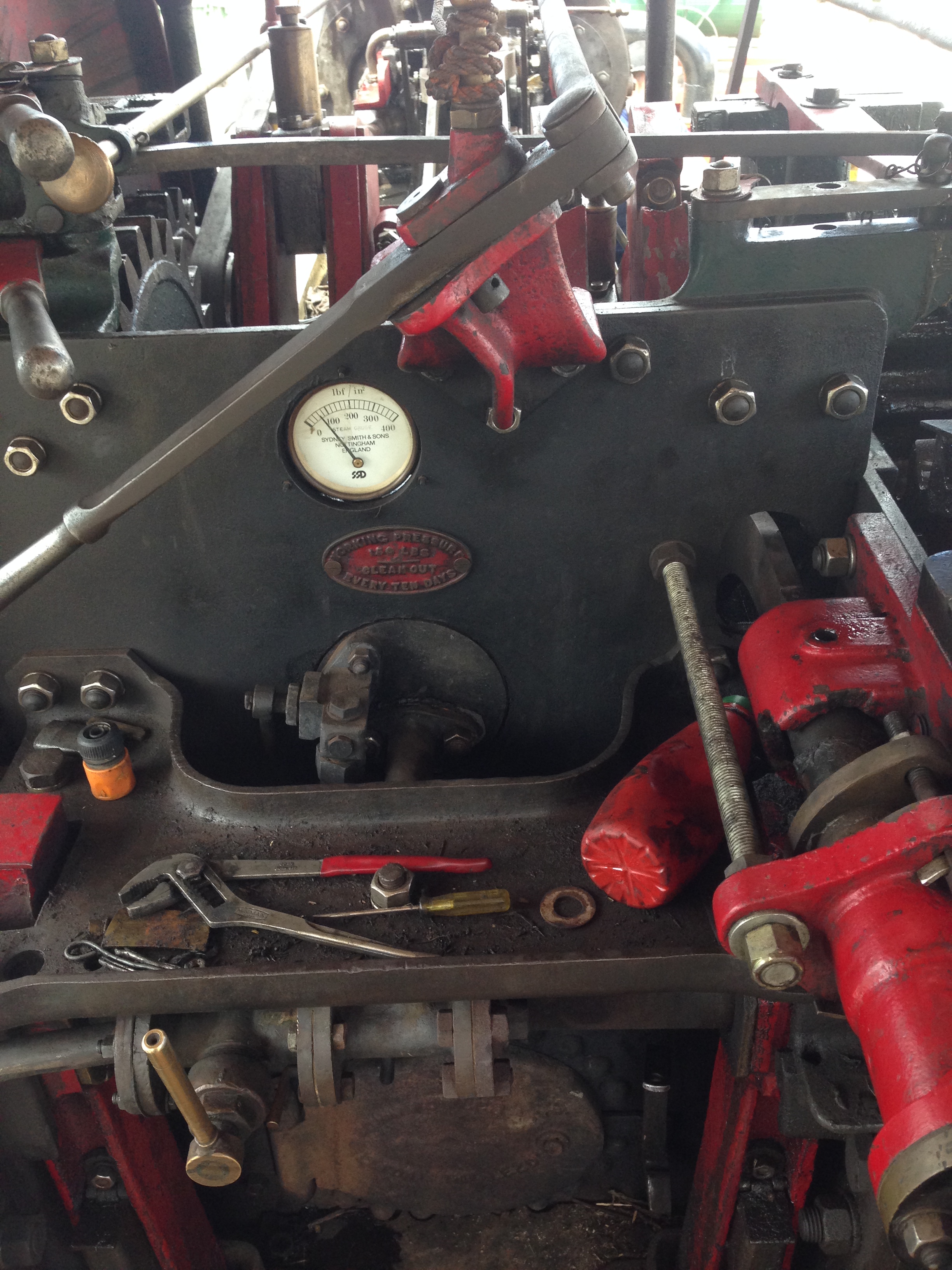
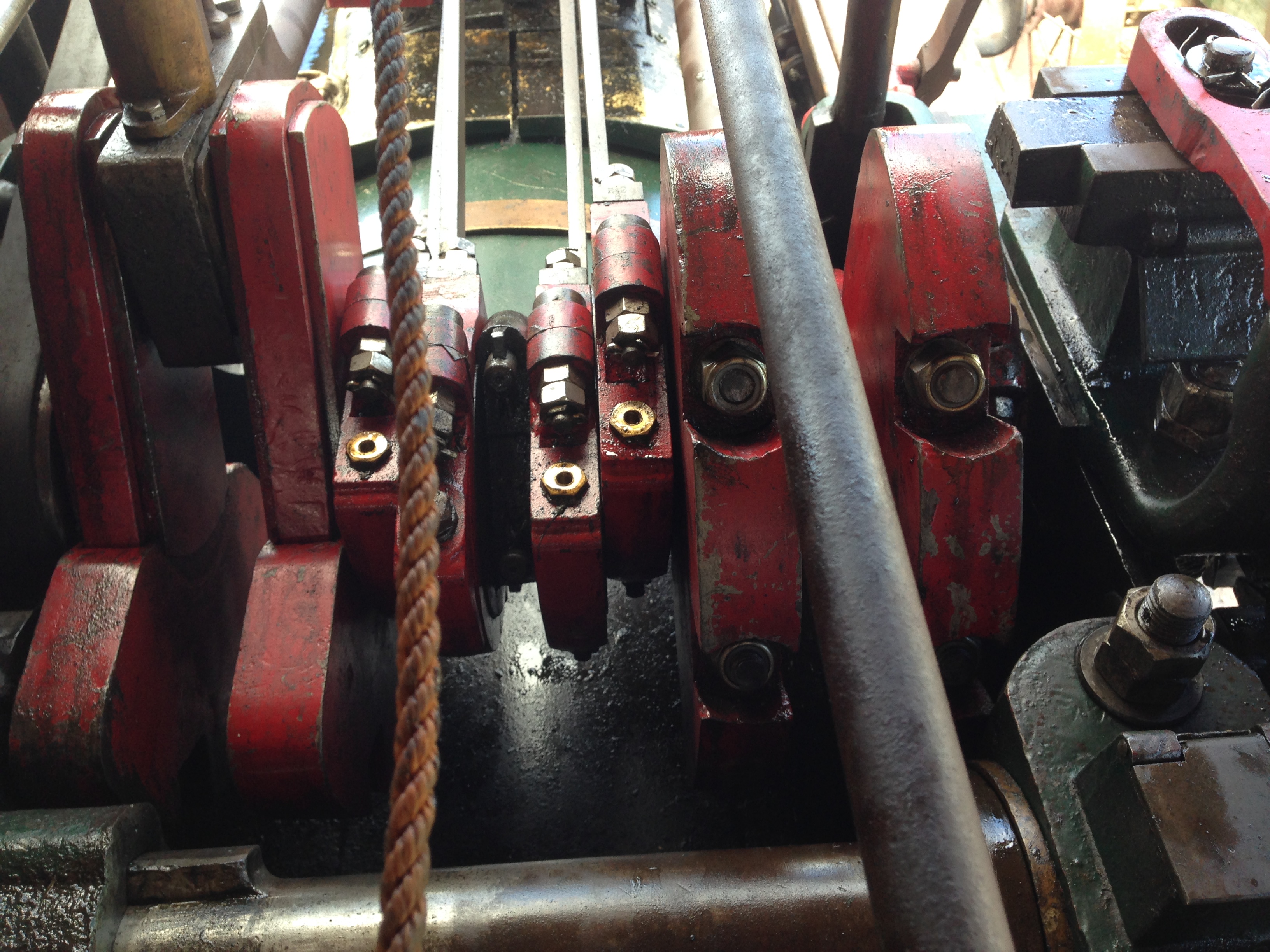
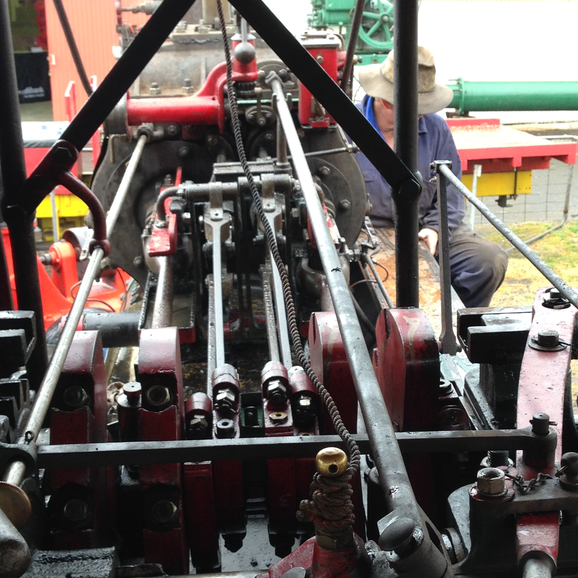
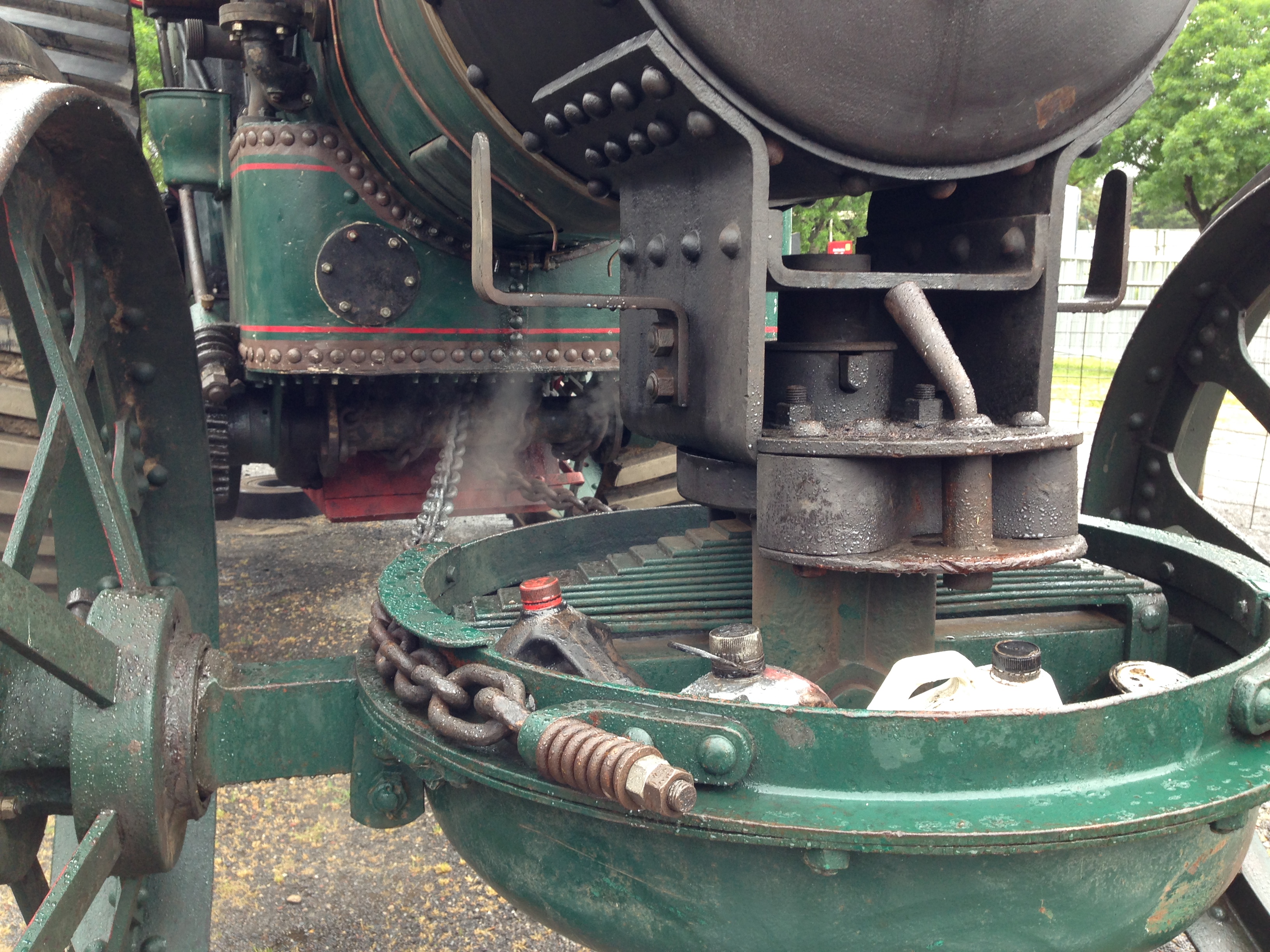
The crank-shaft is at the right of the photo, beneath the big ends, eccentrics and main bearings.
For the third time in a couple of weeks I removed the crankshaft from the engine. The first time took me more than 4 hours. Second time was quicker. Today it took me only 93 minutes, including the time wasted looking for small open enders.
And meanwhile I bought a chunk of steel big enough to carve into a replacement crankshaft….
That lump of black steel is 90 x 90 x 420mm. It weighs 26kg! The faulty crankshaft to be replaced in front. The gear and the eccentrics will be removed in the next workshop session. And the original plans of the crankshaft at rear.
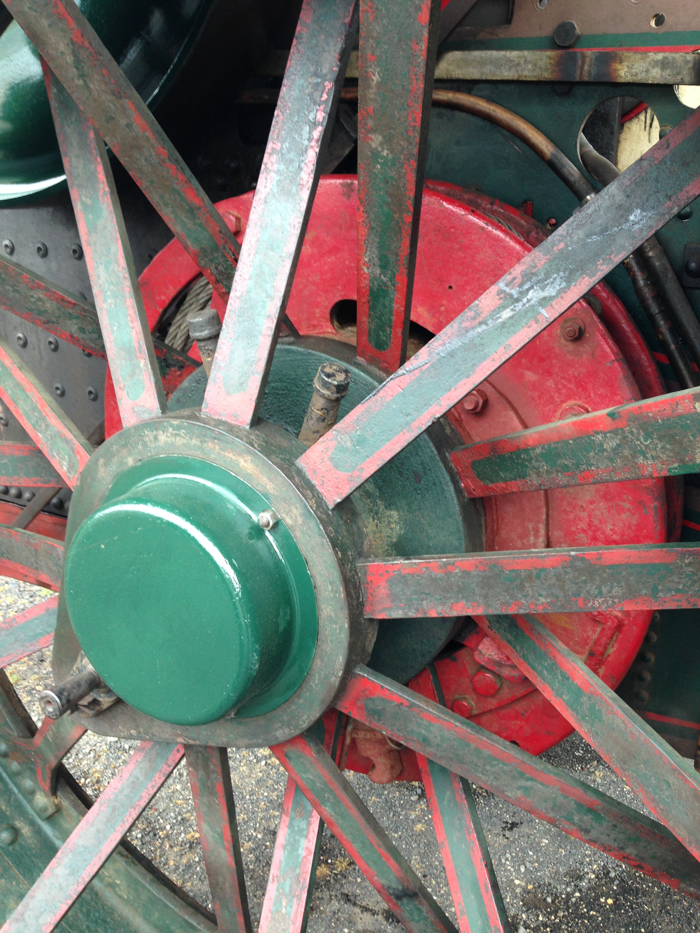
The crank-shaft has two cranks, at 90 degrees from each other. The shaft itself is about 26mm diameter.
My plan is to use the milling machine to remove most of the waste, then to finish the accurate diameters on the lathe, turning between eccentric centres.
It is apparent, looking at the size of the bar, that most of it will end up as swarf. Oh well. On the floor it will keep the tigers out of the workshop.
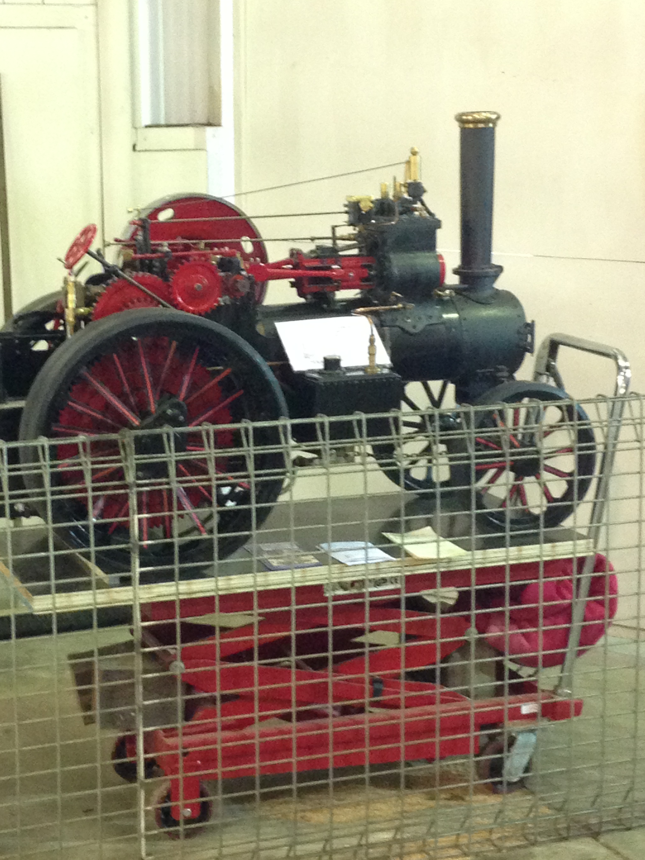
The lovely 1:4 scale Fowler traction engine which I bought in 2017 has had little use in the past 3 years, so I have decided to sell it. The lack of use was mainly due to Covid shut down of steam meets and exhibitions. While Covid restrictions have ceased, my interests have changed, and I now prefer to concentrate on smaller, stationary steam engines.
But first I needed to renew the boiler certification. The boiler is constructed from 4mm thick copper, silver soldered, and was made by an experienced engineer, so I do not expect any significant problems with the re-certification. Just to be sure, I ran the engine on compressed air. Immediately I noticed that the flywheel was rotating more slowly than the crankshaft. The cause was a sheared pin which joins two segments of the crankshaft.
The flywheel has always had a slight wobble, but now it was more pronounced. Obviously the crankshaft needed to be repaired or replaced. Initially I hoped that all that would be required was a new pin. It was a 1/8″ roll pin, and I hoped that I could tap it out and simply replace it.
I have the original construction plans for the engine, and those plans recommend a solid crankshaft in the interests of longevity. However, the original maker had chosen to make a built up crankshaft, securing the 8 joins with roll pins, and probably Loctite.
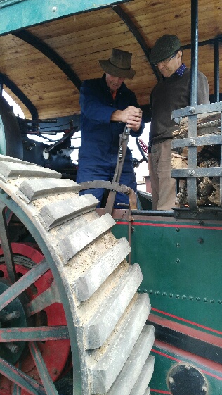
I contacted the original maker of the engine, an elderly gentleman living interstate, and we had a long and pleasant conversation. He was surprised that the crankshaft had failed, but did not recall the details of the construction. He strongly recommended removing the crankshaft from the engine and working on it in the workshop, a decision which I had already made.
Long story shortened. It took me 4 hours to remove the crankshaft, and on the workbench about 10 minutes to punch out the broken pin, and separate the crankshaft parts.
Crankshaft, big ends, eccentric rods, main bearings and flywheel removed.The crankshaft with undisturbed eccentrics, set up on 2 V blocks on a granite surface plate. With the 2 parts pushed together. But something was wrong. With the broken end clamped in the V block, the other end was held about a millimeter above the V block. WTF!
By this time the join had been cleaned with acetone, primed with Loctite 7471, and glued with Loctite Wicking 290. And reamed the hole to accept a number 1 taper pin.
So I checked the diameters of the mainshaft at both ends. 23.47mm at the broken end. 22.86 at the high end!!! Bugger. I should have checked before gluing. But why would the mainshaft have different end diameters???
Oh well! I decided, foolishly with hindsight, to reassemble the whole engine and see if the discrepancy was noticeable.
Next day, another 4 hours, and the reassembly was complete.
Rotated the flywheel. And it was horrible!! The flywheel runout was not “noticeable”. It was horrible!!
It had to be redone. Or do I just bite the bullet and make a new crankshaft?
I decided to redo the repair job, lining up the parts in the lathe.
Long story short again… teardown was much quicker this time. Experience counts.
This time I took a very light skim off the shaft and face using a very sharp cutter, to ensure that the ends and roughness were removed. Then held the broken shaft in a collet chuck which I know is very accurate. But found another problem. The shaft at the other end of the crankshaft had not only a smaller diameter, but was also at a slight angle axially, so I could not use the machined centre in the end of the shaft. So I set up the fixed lathe steady pictured, mounting it at the main bearing location. Trouble was that I had no accurate method of centering the steady. I described this setup to my engineering group, and was informed that I should have used a set up rod machined to the diameter of the end of the crankshaft, to set the position of the steady. Makes sense. My bad.
Oh well. I will reassemble the engine again. If it is again horrible, I will either do the whole job again, properly this time, OR MAKE A NEW CRANKSHAFT.
I have a feeling that I will be making a new crankshaft.
p.s. I allowed a day for the Loctite to cure, then deeply reamed the existing hole, and reinserted the taper pin in the enlarged tapered hole. This time the head was buried, but there should be enough purchase to remain intact.
Reassembled the engine, and turned it over to check the flywheel wobble.
I will not claim that it is perfect, but it is very close. I will not start making a new crankshaft just yet, but that is the next step if this repair is eventually unsatisfactory.
Click on the picture to see a short video of the Fowler R3 steaming away.
Dear Reader, if you follow my posts you will know that I had stopped posting on WordPress because I had exceeded the 13gB memory limit.
I have been copying old posts to medium.com, and posting new ones there. Today I was copying some more, and I happened to notice that my wordpress memory limit had increased. There had been no notification of an increase. Maybe it was a mistake. So I posted the above video as a test, and to my surprise it was accepted. So I contacted support to see if there had been a change of policy. No, no policy change. Apparently it was a bug. Could it have been someone being kind? I asked. Possibly, was the reply. Do you want it changed back? NO!! I screamed.
So I have a 10gB reprieve. Enough for several years at my rate of usage. May be temporary. Time will tell. Meanwhile I will recommence posting here on WordPress, as well as medium.com/@johnsmachines
Very few of my johnsmachines.wordpress readers have switched to medium.com, so I was seriously considering pulling the plug on all future posting. So this is a reprieve. You will have the choice of seeing my posts here on WordPress, or at Medium.
P.S. The traction engine, tender, kids cart, custom fitted trailer with winch, and ~200kg of steaming coal is for sale. Located near Geelong, Victoria, Australia. Best offer over $AUD20k. Certification will be renewed prior to sale. Kids not included.
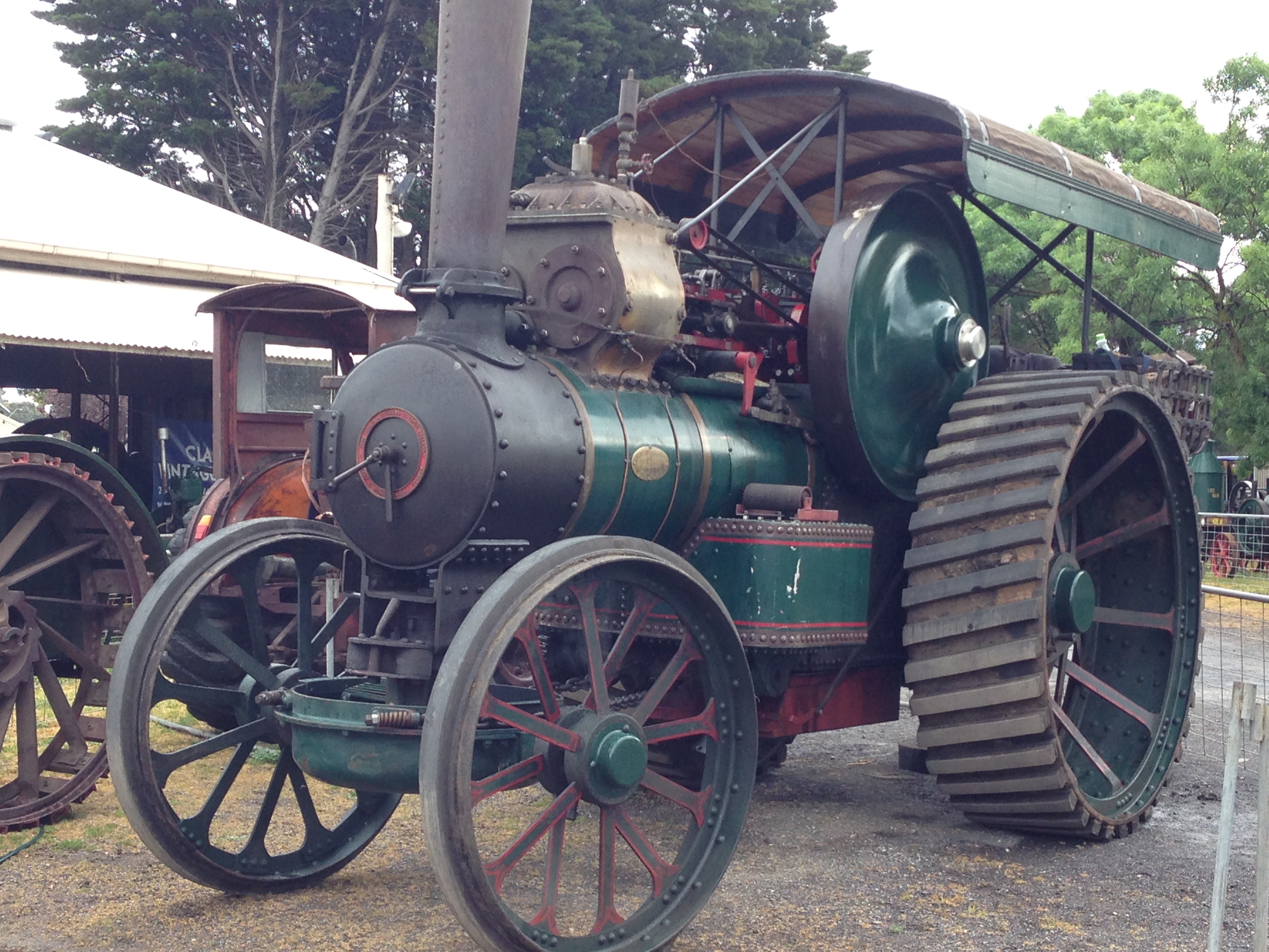
My 3″ Fowler R3 Traction Engine boiler can be filled with a hand pump from the tender tank, by a crankshaft powered pump from the tender tank, or by a battery powered electric pump from the driver’s trailer. The full size original R3 (see previous post for photos) has a steam powered injector, which uses boiler steam to suck up water from the tender tank using a venturi effect, then using black magic passing the steam+ water through some cones, increases the pressure which forces the mixture back into the boiler.
Here is a link to a YouTube site which sort of explains how the black magic works.
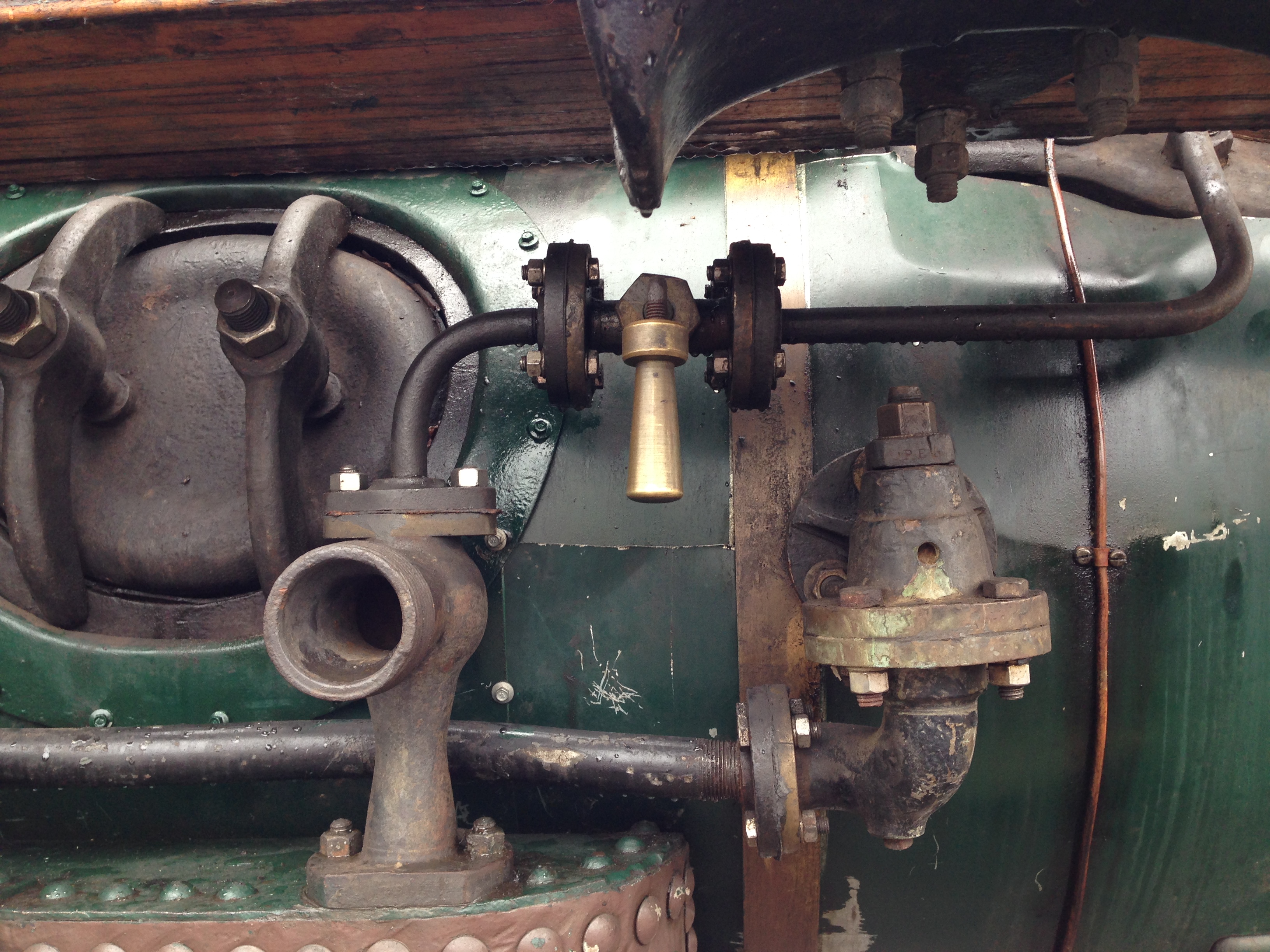
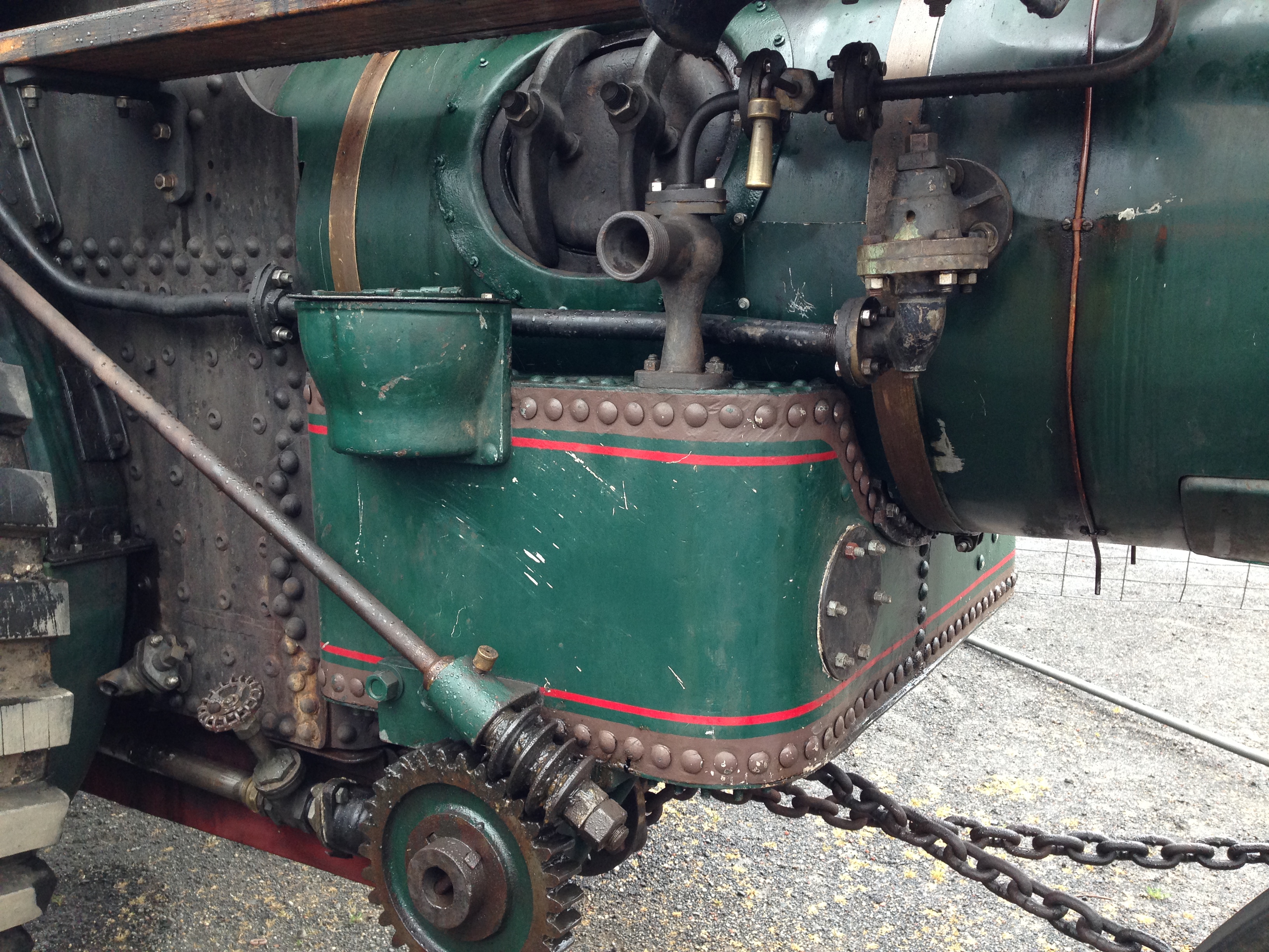
And this is the steam injector on the full size R3 Fowler.
And this is the injector which I bought for the 3″ scale Fowler.
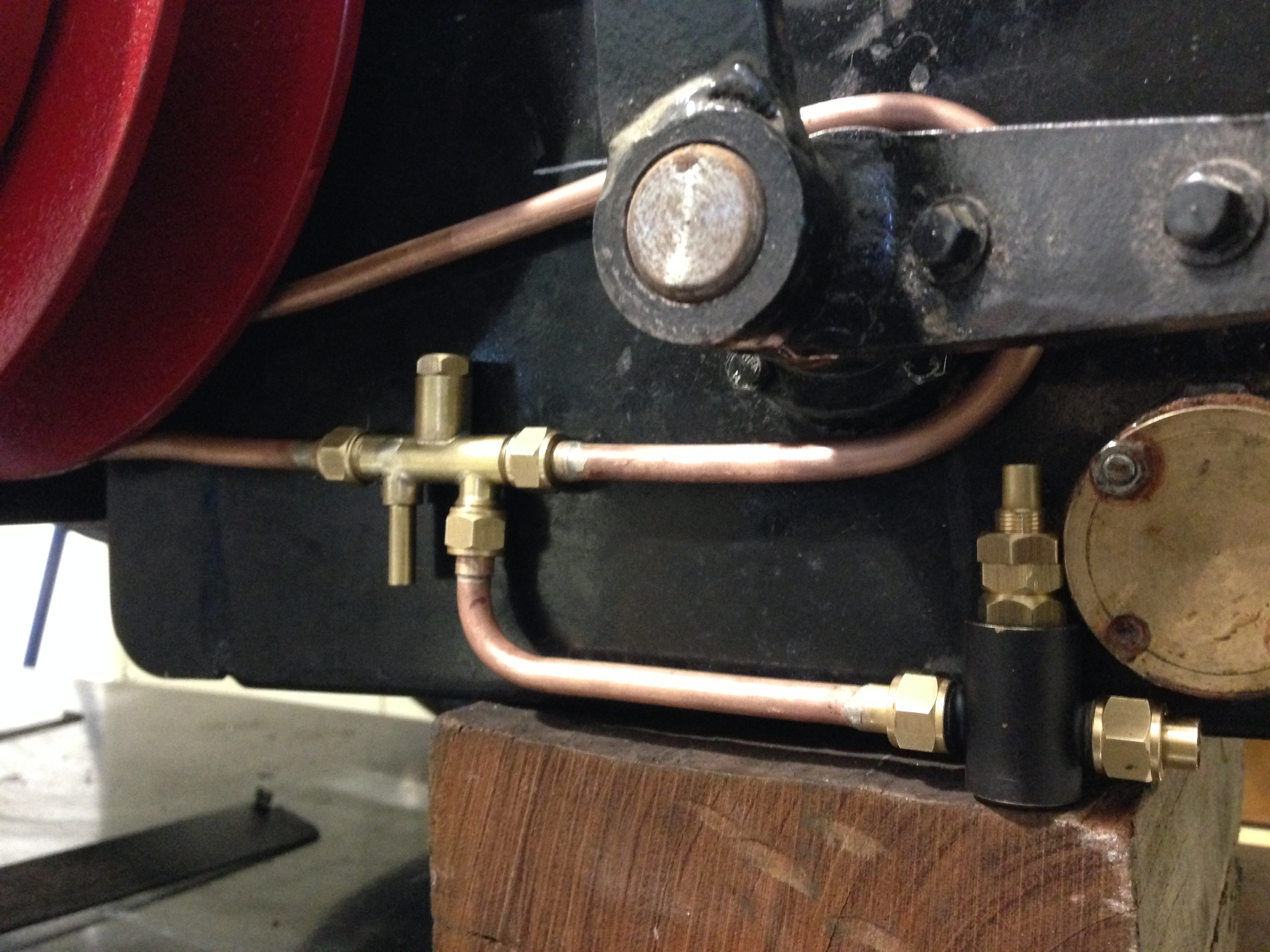
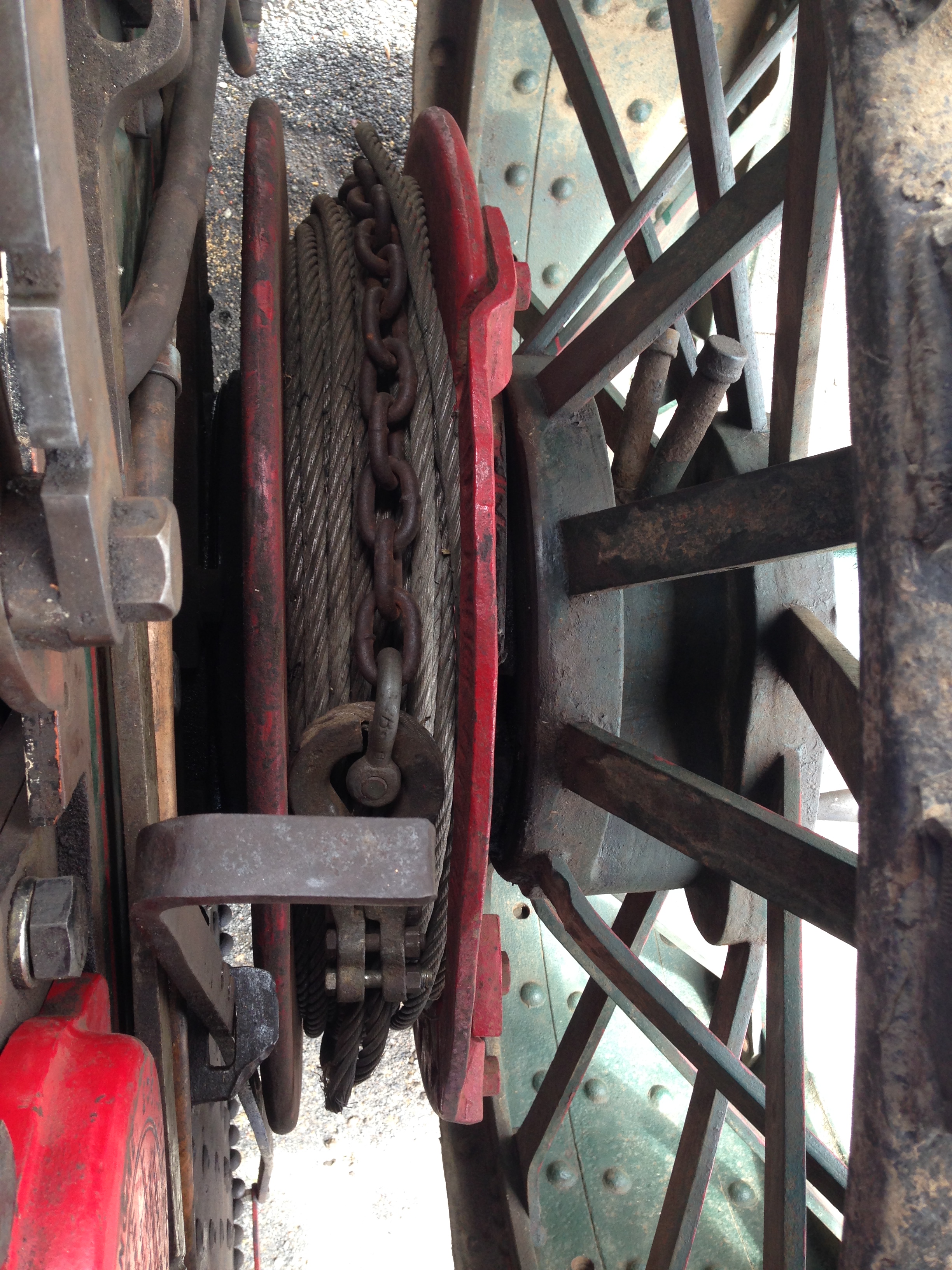
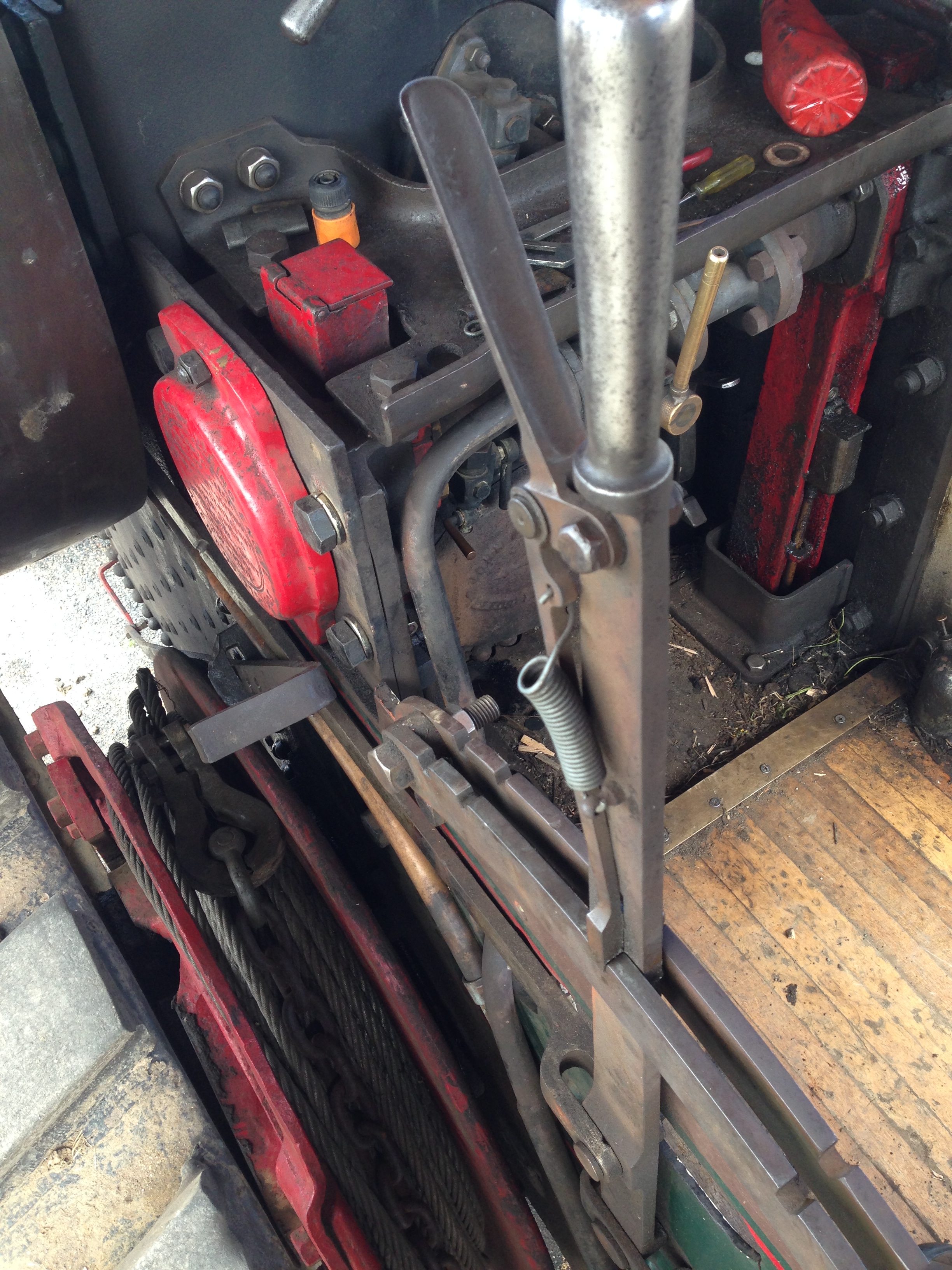
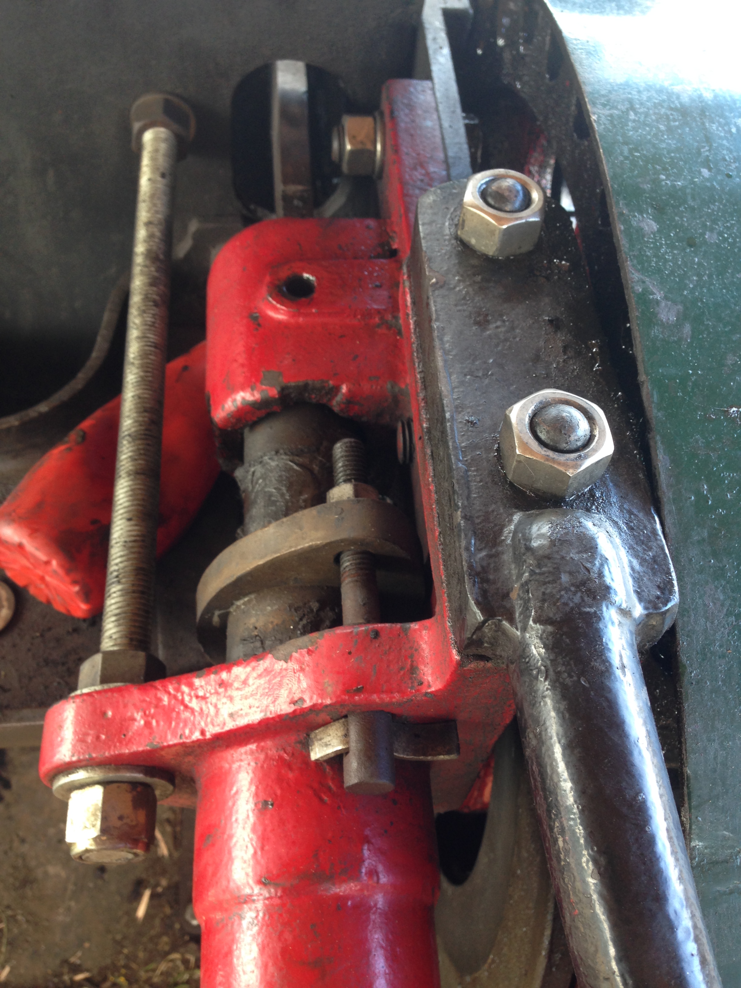
It is a vertical injector, with connections for 1/4″ (6.35mm) pipes. But I did not use it because it protruded too far underneath the tender. So I have used an identically sized horizontal injector, which is shown below, during installation. The full size original also appears to be horizontal. The black fitting connected is the water inlet valve. The control handle will extend above the rim of the cockpit.
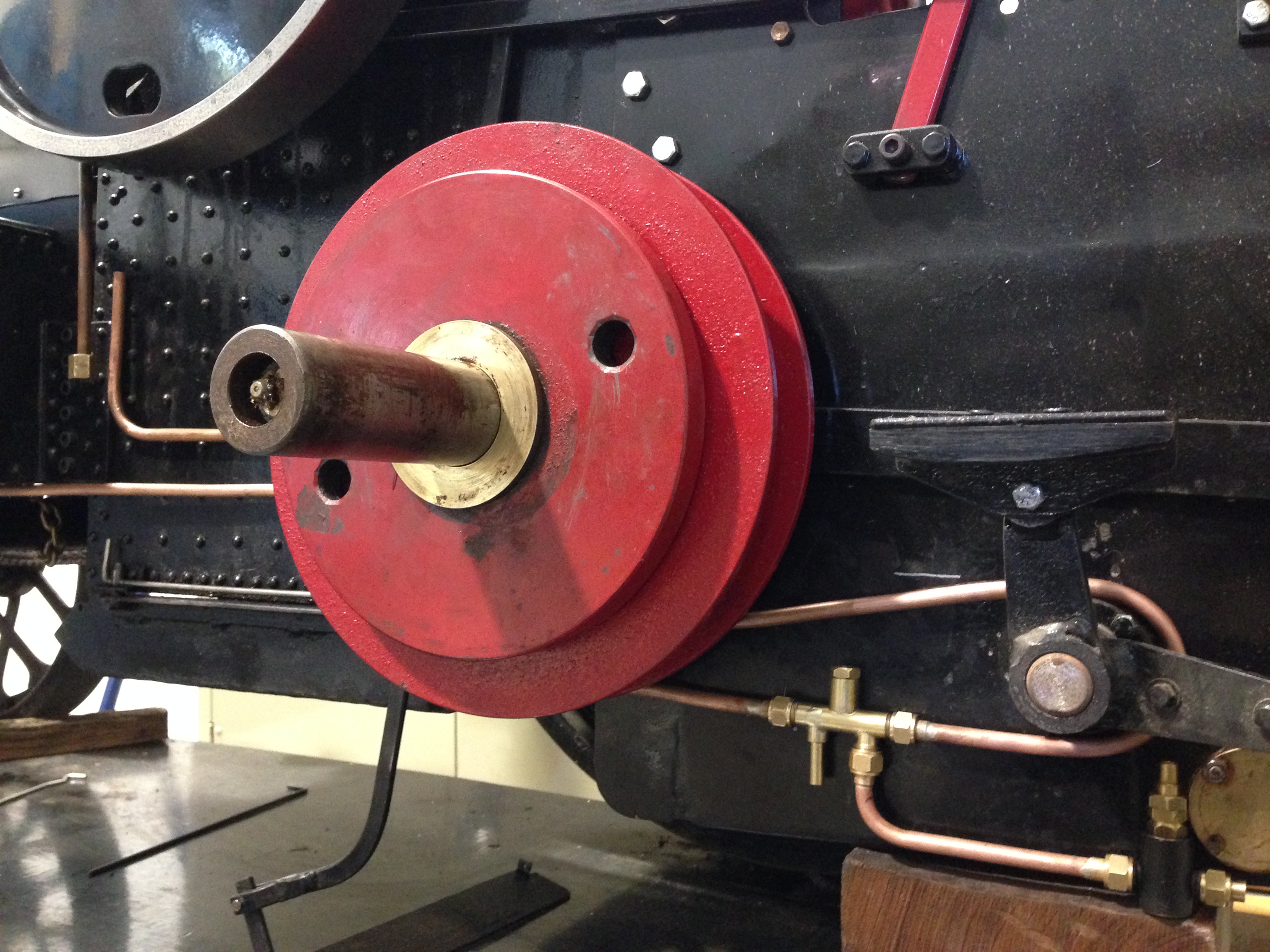
The red thing is the winch, and its driving disk. Winch engaging pins have never been completed, another job for later. The rear wheel has been removed. The injector pipework passes between the winch drum and the hornplate, with just enough clearance. Running the pipe around the brake axle seemed like a good idea at the time, but I am not so sure now. When painted black it will not look so odd. The water connection with the tender tank is yet to be made, as is the steam supply connection. A few more hours.
Today I loaded the Fowler 3R traction engine onto its trailer and drove to Werribee, to have an official inspection of the boiler.
This is not a legal requirement, because I can operate my traction engine whenever I please on my own property. But all model engineering Clubs and Societies require a current certificate before they will permit steam engines to be operated at their meetings.
The maker of my traction engine had the boiler inspected and passed about 18 months ago, but that certificate has now expired. So it needed re-certification.
The original test pumped water into the boiler at double the maximum operating pressure to test the boiler for leaks and distortion. The boiler is actually designed to withstand pressures of EIGHT times maximum operating pressure, so the safety factor is reassuring.
But, boiler explosions are horrific, so the caution is understandable.
My boiler is made of copper, thus avoiding the problem of steel boilers which gradually becomed thinned by rust. And my boiler seams were joined by silver soldering, which, if expertly done is as strong as the parent metal. As a matter of interest, the maker of my boiler told me that he had used $AUD1000 of silver solder in the construction of the boiler decades ago!
The test today involved pumping water into the boiler at 25% above maximum operating pressure, and holding it there for 20 minutes, checking the boiler for leaks and distortion. It passed that test without problem.
The next test was for the functioning of the safety valves. I had cleaned them and replaced the balls and polished the seats, and I had seen them blowing off when the pressure was above 100psi, so I was fairly confident that the certification was “in the bag”.
So the fire was lit, and after some coaxing because I had stupidly forgotten to bring the chimney blower, the steam pressure was raised to 100psi. The safety valves started venting off. But, the test is fairly demanding. The fire was roaring, the steam blower was turned on full, and the pressure continued to rise. It rose to 120psi which fails the test because the safety valves should have released enough steam to keep the boiler pressure at 100 psi or 110psi maximum.. Some adjustments to the safety valves did not fix the problem.
Some machining will be required to fix the valves, but after consideration I have ordered brand new safety valves and the test will be re-done when the new ones are fitted.
The boiler inspector was quite particular and proper, and very helpful. I am grateful that this safety issue was detected, and I totally agree that it has to be fixed. Thinking back to my problem of about 1 month ago, when I “dropped the fire”, (see “Holes in Swiss Cheese) I now believe that the problem was partly caused by the inadequate safety valves.
Add one more hole to the Swiss Cheese theory of disasters.
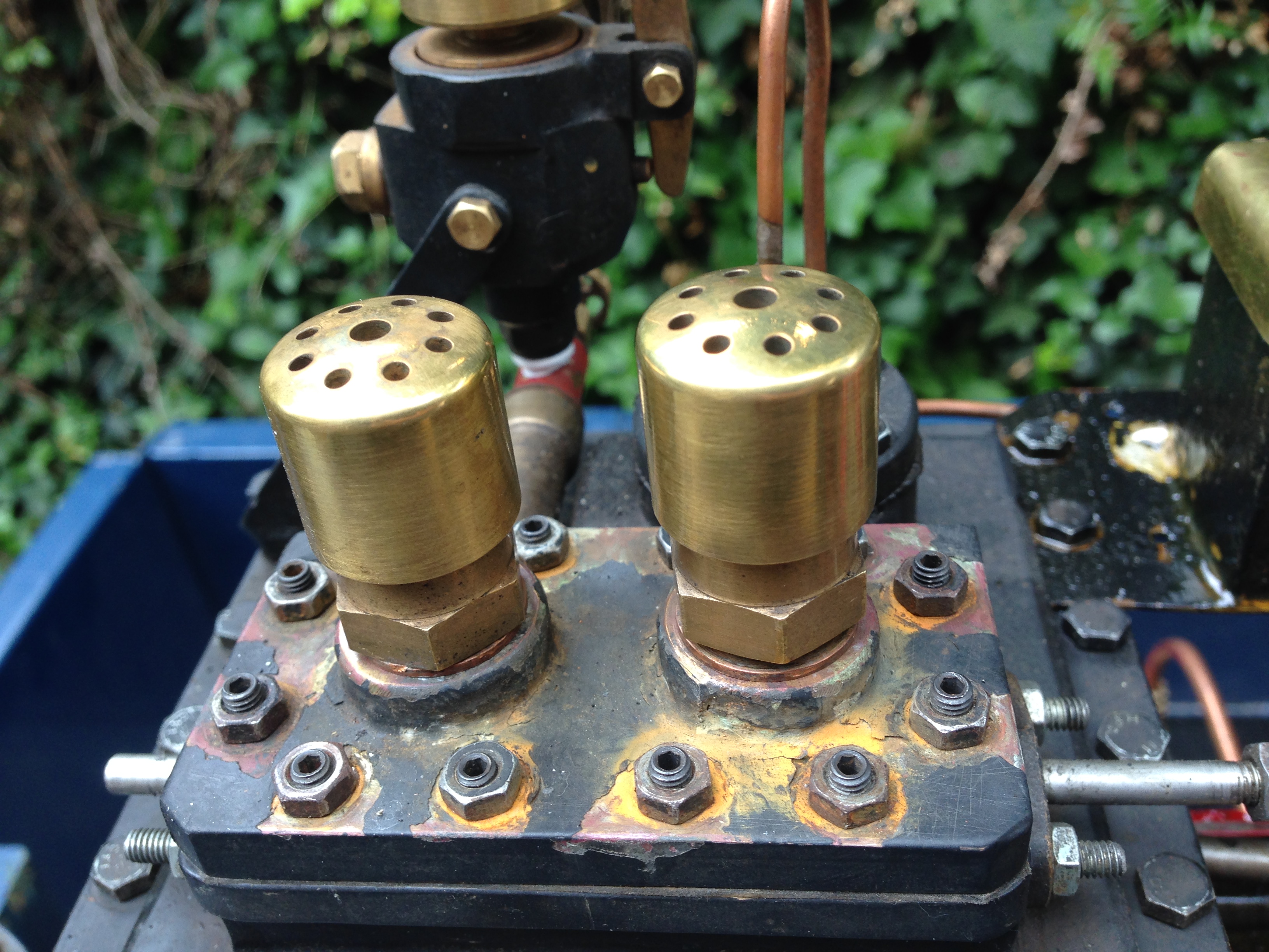
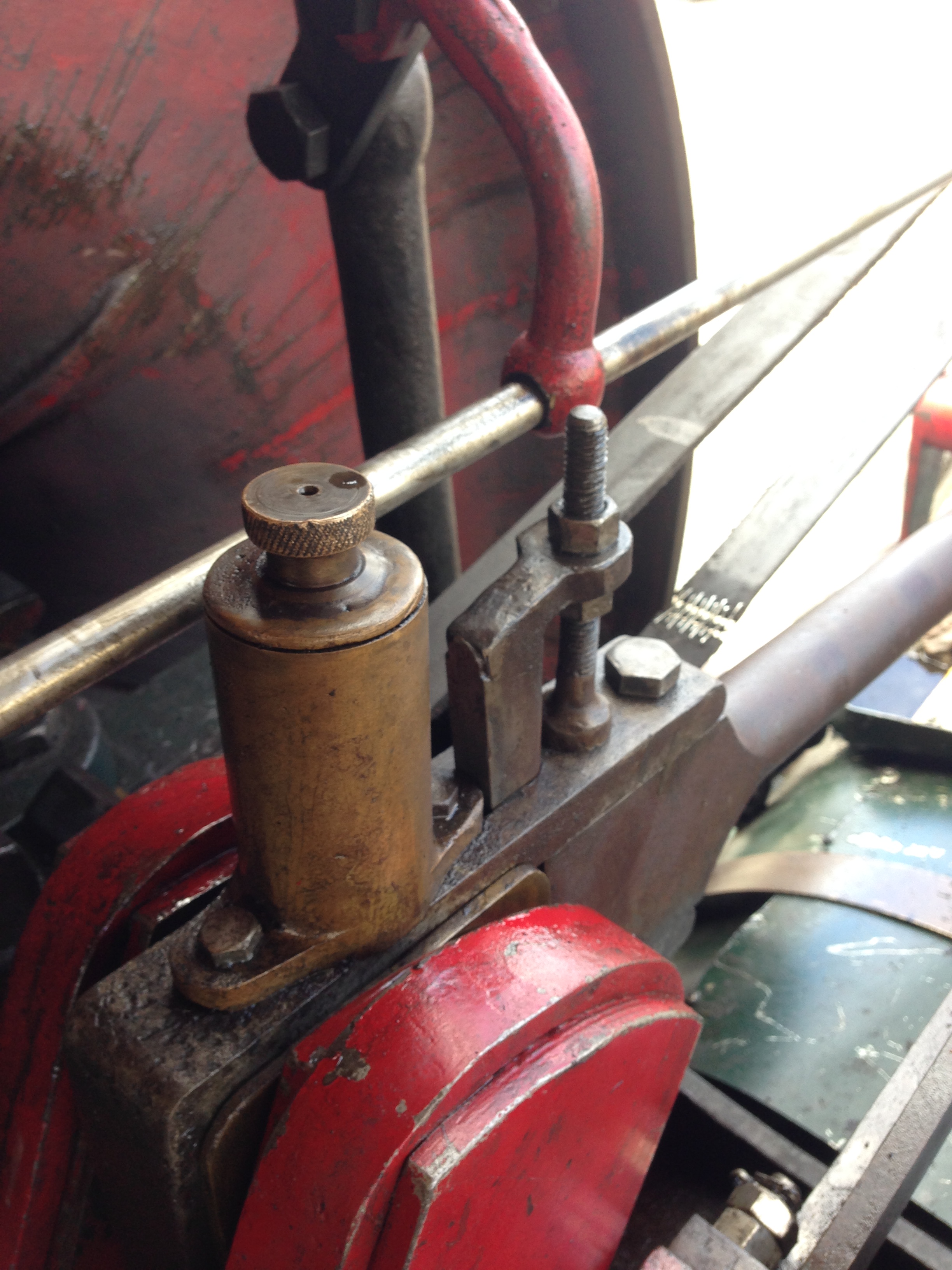
The inadequate safety valves.
The safety valves AND the oiler were replaced.
The new safety valves arrived today. Warrick Sandberg valves. I will install them later this week, and fire up the Fowler R3.
The old safety valves. Not up to the job.
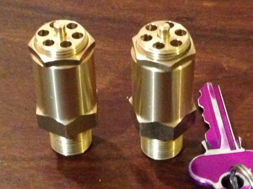
The new safety valves. about the same dimensions but the exit holes are bigger and the spring tension is adjustable and lockable.
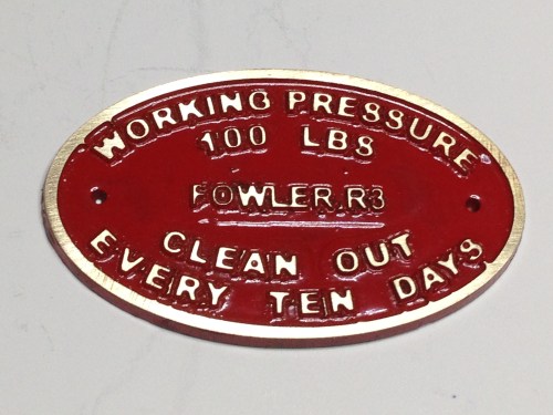
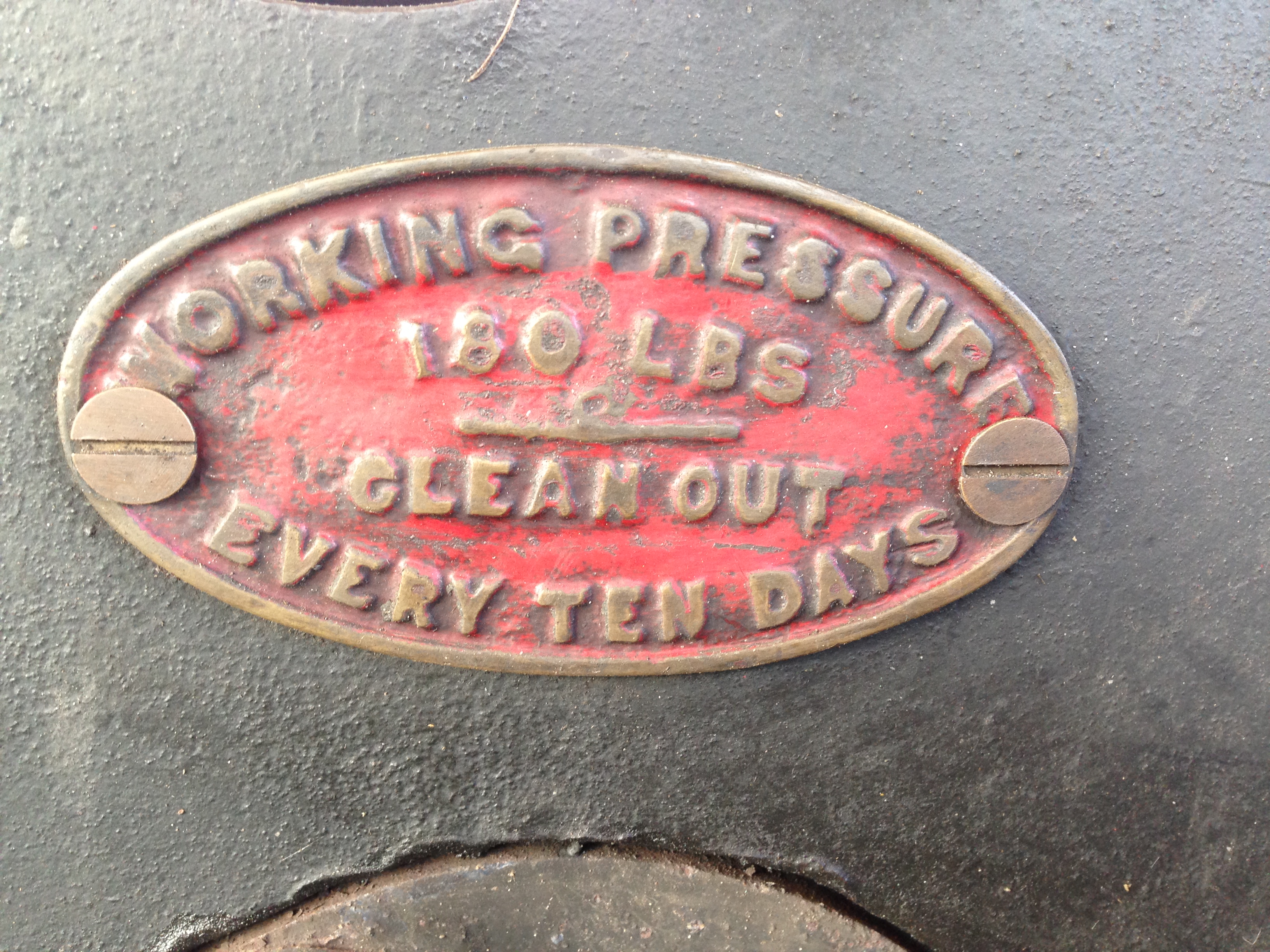
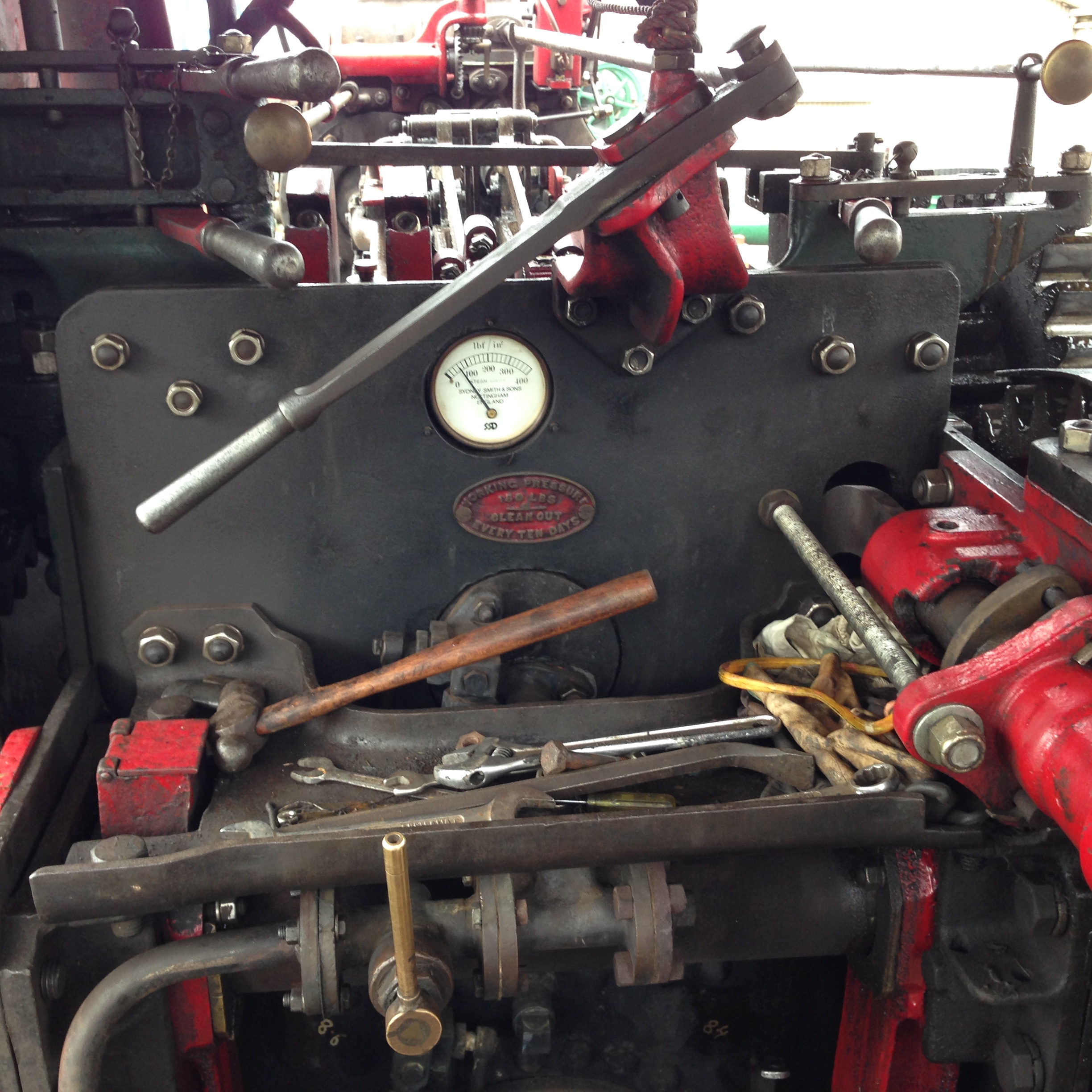
And another thing. I noticed this label near the pressure gauge of the full size Fowler R3.
So I made this one today. Slightly modified the information to suit my 3″ scale Fowler.
My enamelling technique could improve, but it will do.
I took my Fowler R3 3″ scale traction to the Geelong Show, and here it is on display.
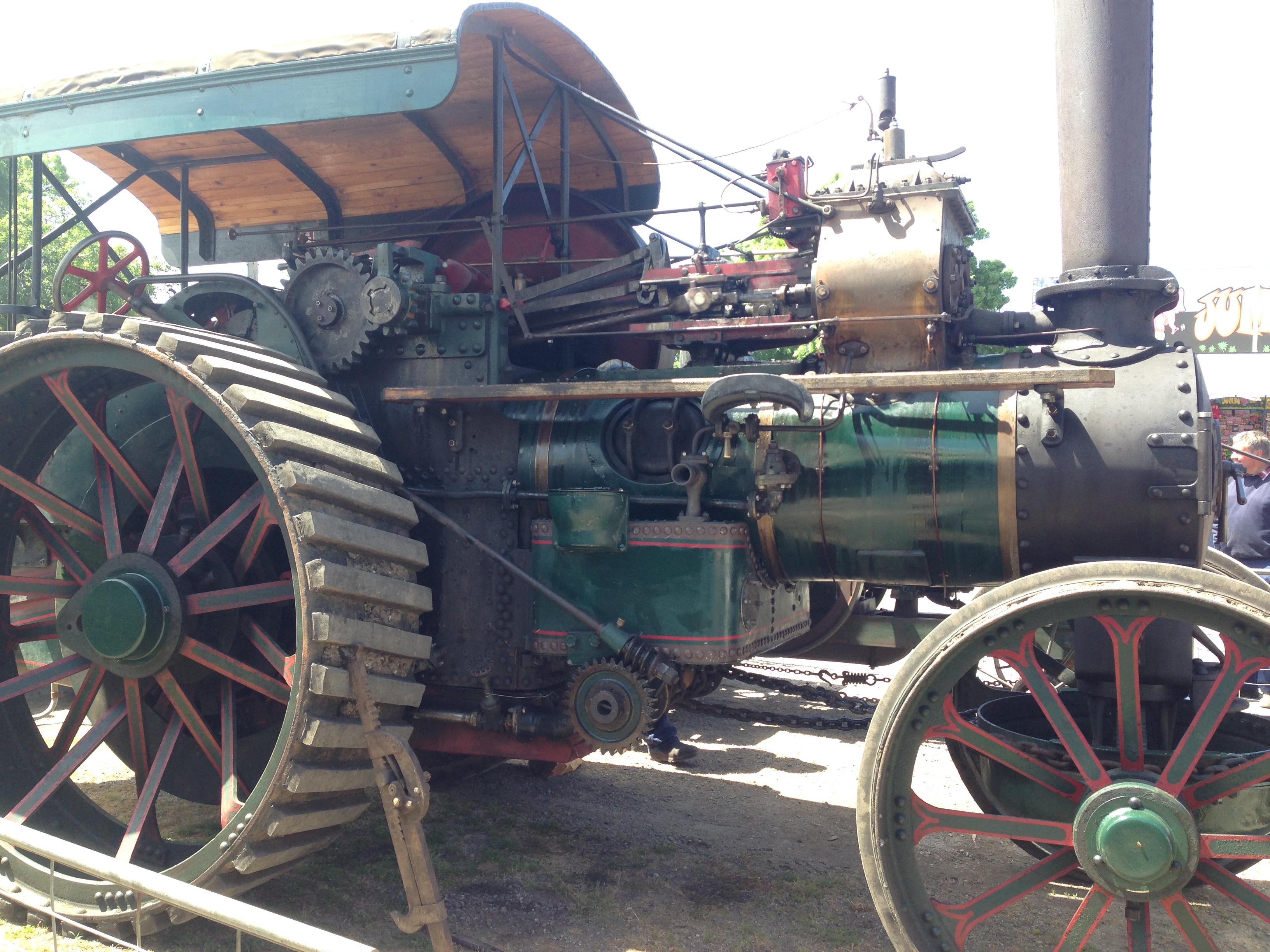
The R3 is a bit of an uncommon traction engine, so I was rather surprised, delighted and awed to find a full size R3 on display also. Of course I met with the owner and spent a lot of time talking to him and examining the real McCoy Fowler R3. Apart from the size difference, the similarities were striking. Even the colour scheme was similar. And the full size machine was a heavy haulage model whereas mine is a road locomotive.