USS Constitution Scrimshaw
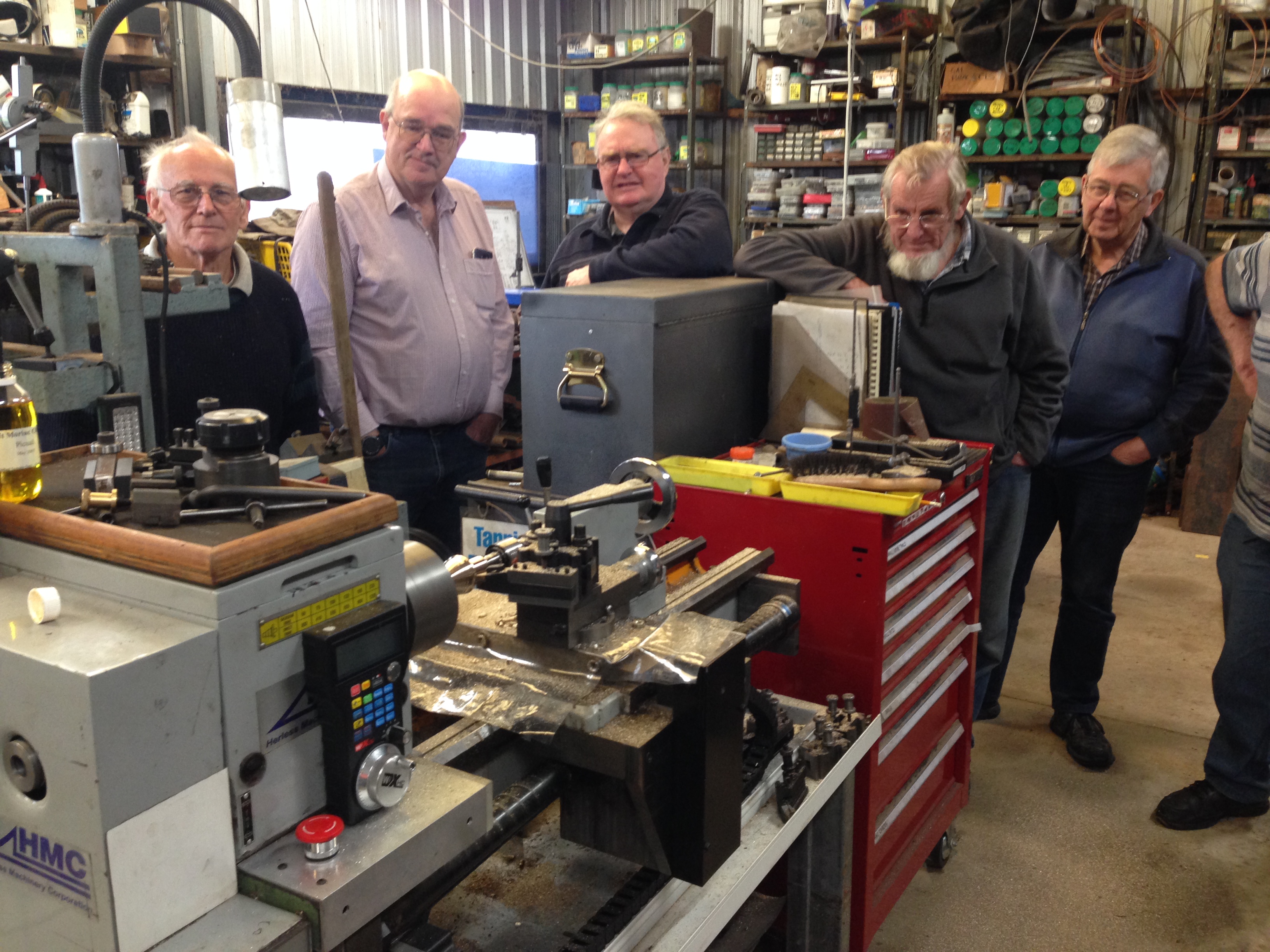
At our Wed morning model engineering meeting today I gave a short talk on meshy.ai
I came across this AI software a couple of days ago, on Ships of Scale, and immediately downloaded it and played around with it for 2 days. Frankly, it will change the hobby of modelling. Ships or scarey monsters or whatever. I will add another post about it in a day or two.
But the highlight of today’s GSMEE meeting occurred when a member showed us an example of scrimshaw which he had acquired at least 4 decades ago.
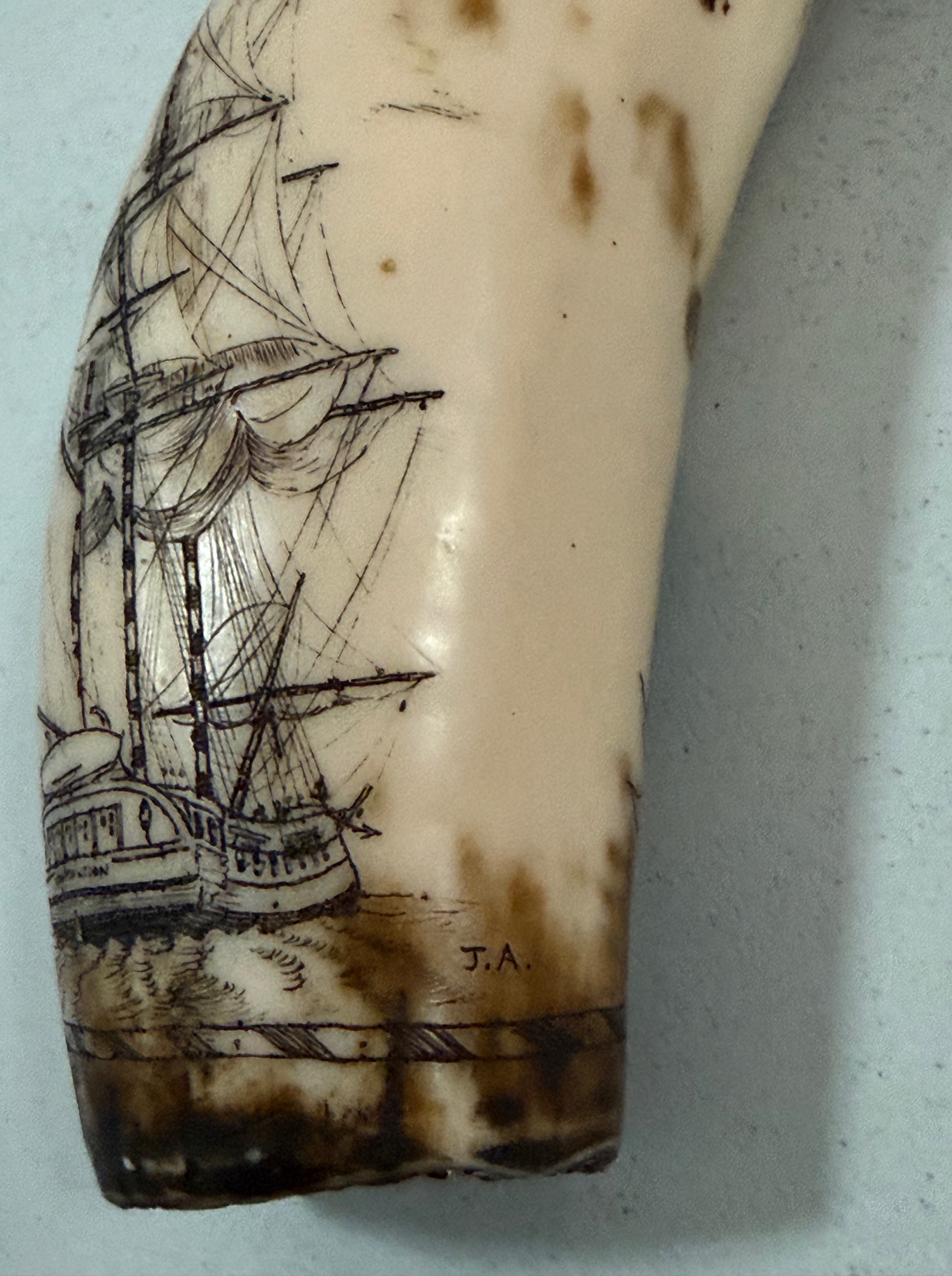
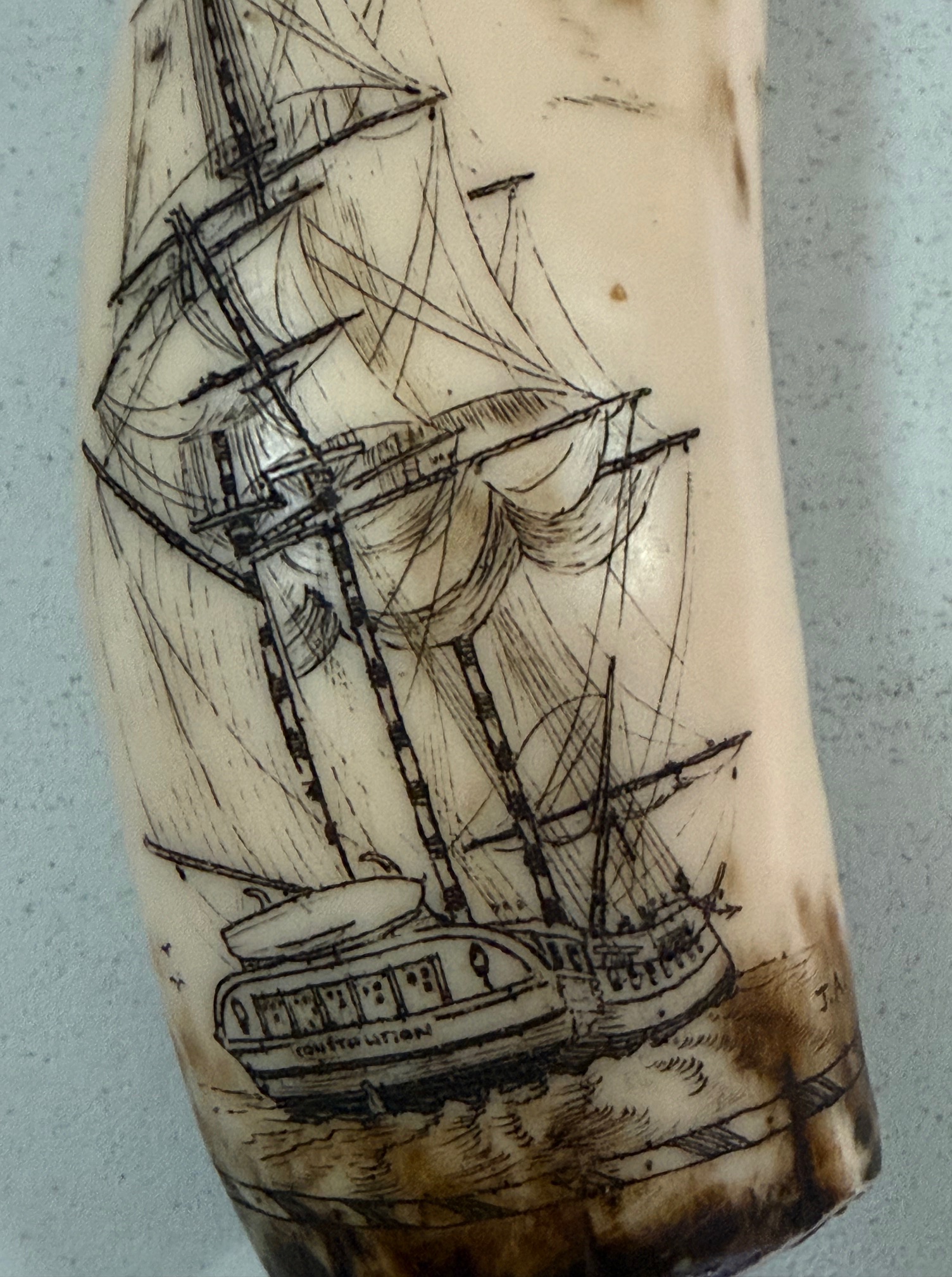
The sailing ship looked familiar to me. I could not read the name on the transom, so took a photo and enlarged it. Sure enough, and to my absolute delight it read CONSTITUTION.
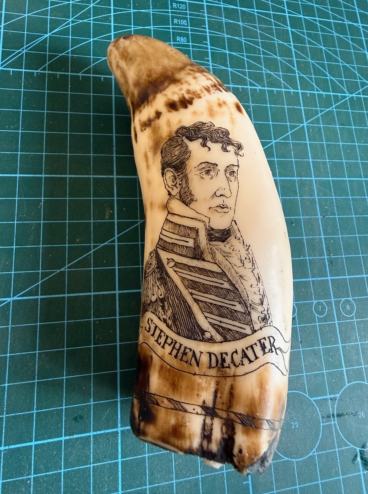
Of course I immediately recognised the name “Stephen Decater” having recently read the 580 page “Six Frigates, the epic history of the founding of the S Navy” by Ian Toll. Although the accepted spelling of” Decater” is actually “Decatur”. He is almost as famous in the USA as Nelson is in Britain.
Another member took some photos and asked for an opinion from his AI. It reported that it was a cheap epoxy tourist trinket, not bone or marine tooth. But even so, I was thrilled to inspect the detailed Constitution rigging, and the very clear portrait of Stephen Decatur.
The owner offered me the item to inspect more closely, which I did at home. I took better photos and submitted them to Chat GPT.
The ChatGPT report was that it IS genuine scrimshaw carved into marine bone or tooth, and probably late 19th or early 20th century scrimshaw. The fine detail, name on the ship, and carver’s initials indicate that it was made on shore rather than on a whaler or sailing ship. And it suggested a value of $800-$2500 !!
Another one of our GSMEE members has a brother who collects scrimshaw, and has several hundred pieces. We will wait his opinion with great interest.
Meanwhile I have the item for the next week, and am enjoying gazing at it.
p.s. I had uploded this post to WordPress before my notification that my storage limit had been reduced to 13gB. So this will actually be the last post.
p.p.s. 5 Feb 26 The expert opinion on the scrimshaw in the photos come from the brother of one of our model engineering club members. He has a personal collection of hundreds of pieces of scrimshaw, and is an acknowledged expert on the subject. His verdict is that the black filling on the inside of the piece confirms that it is not genuine scrimshaw. i.e. not carved on marine bone/tooth, and not carved on a 19th century whaling ship. The black filling was commonly used on the fake scrimshaw to conceal the inside of the piece, which would have immediately confirmed that it is not marine bone/tooth. The expert valuation is $aud30-$70.
How disappointing.
However, it is a nice representation of USS Constitution, in which I have a personal interest, and I have offered the owner $70. Negotiations might follow.