machines which I have made, am making, or intend to make, and some other stuff. If you find this site interesting, please leave a comment. I read every comment and respond to most. n.b. There is a list of my first 800 posts in my post of 17 June 2021, titled "800 Posts"
Installed the rotation preventer yesterday. It stops rotation movements when the mill-drill worktable is raised and lowered.
The brackets and linear stage rails were bolted together after positioning the brackets on parallels on a machined surface table (from the now closed Ford factory).Then attached the assembly to the column by bolting together the halves of the brackets. A bit of adjusting of tensions to get the slide working smoothly on the rods, then bolted the linear stage to the gear enclosure with 2 more cap screws. The Metabo drill provides plenty of power through the worm and gear to raise and lower the heavy worktable, and the drill electronic speed control provides excellent control.
When everything was tightened, No worktable rotation movement at all was detectable, even when pushing on it, and the raising and lowering movements were unaffected. It is a rigid setup.
So, how accurately is the position maintained during raising and lowering?
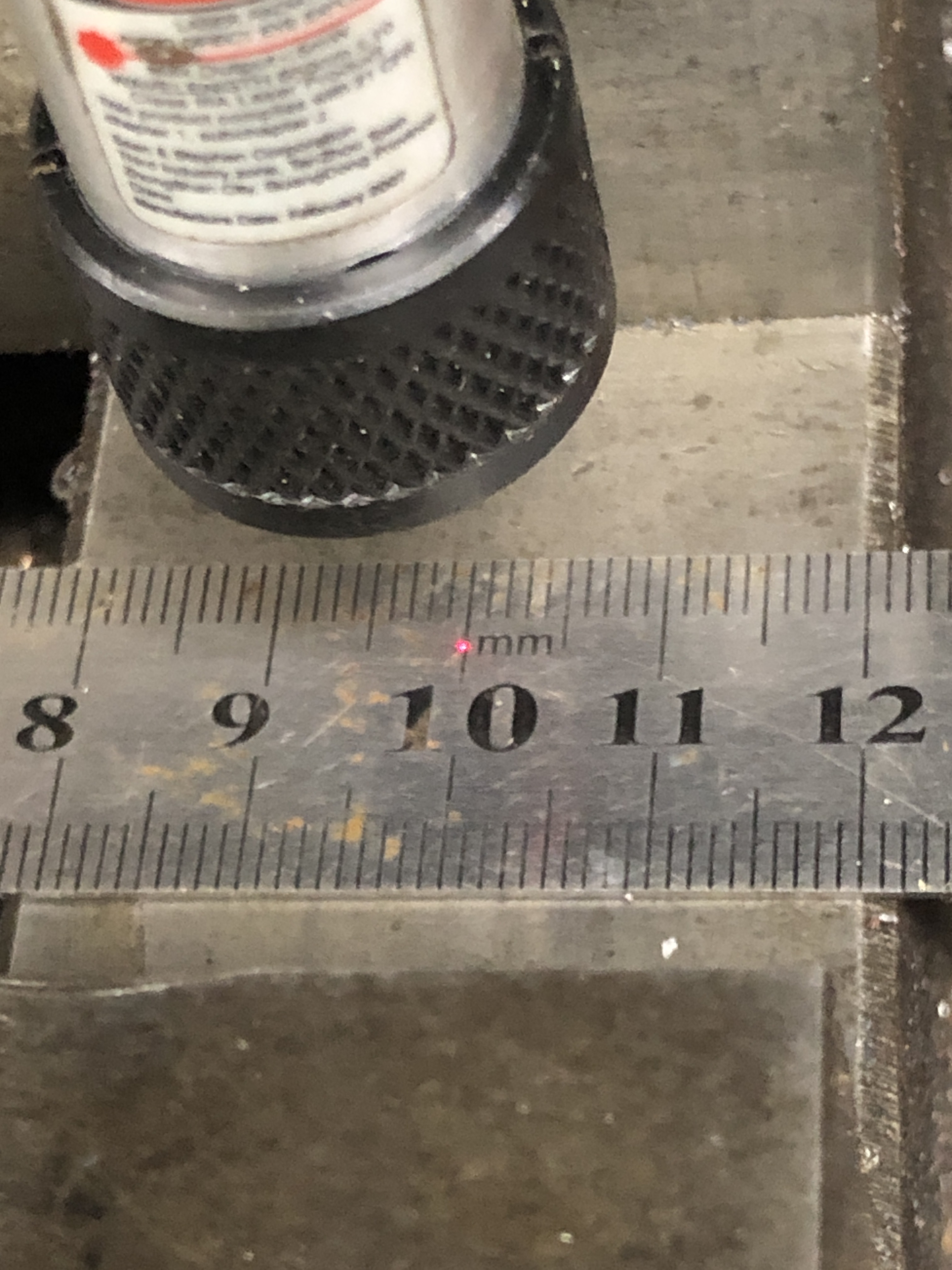
A laser pointer was set on a millimeter scale. Not super accurate, I agree, but should give some indication. The laser is only 40-50mm from the scale.
Then lowered the worktable about 300mm.
The laser dot is bigger at this distance but it is still centered on the same point.
This setup feels really rigid, and I feel pretty sure that it will work well.
Discounting the cost of the incorrect specifications of the first laser cut parts, the overall cost was about $AUD400.
The traction engine crankshaft is installed, and just needs valve timing for the job to be completed. But I am taking a break from that project to get back to the mill drill attachment to prevent work table position changes when adjusting the table height.
I had bought a used linear stage mechanism…..about the same cost as 2 pieces of ground 30mm shaft, but it included the precision bearings in the stage table.
… and had some 20mm mild steel plate laser cut to attach the linear stage rods and table to the mill drill….
…… but unfortunately got one of the dimensions wrong and had to scrap the laser cut cut brackets, remeasure them, redraw them, and order more laser cut parts. An expensive mistake.
Anyway, the new parts were collected yesterday, and today I started to machine them.
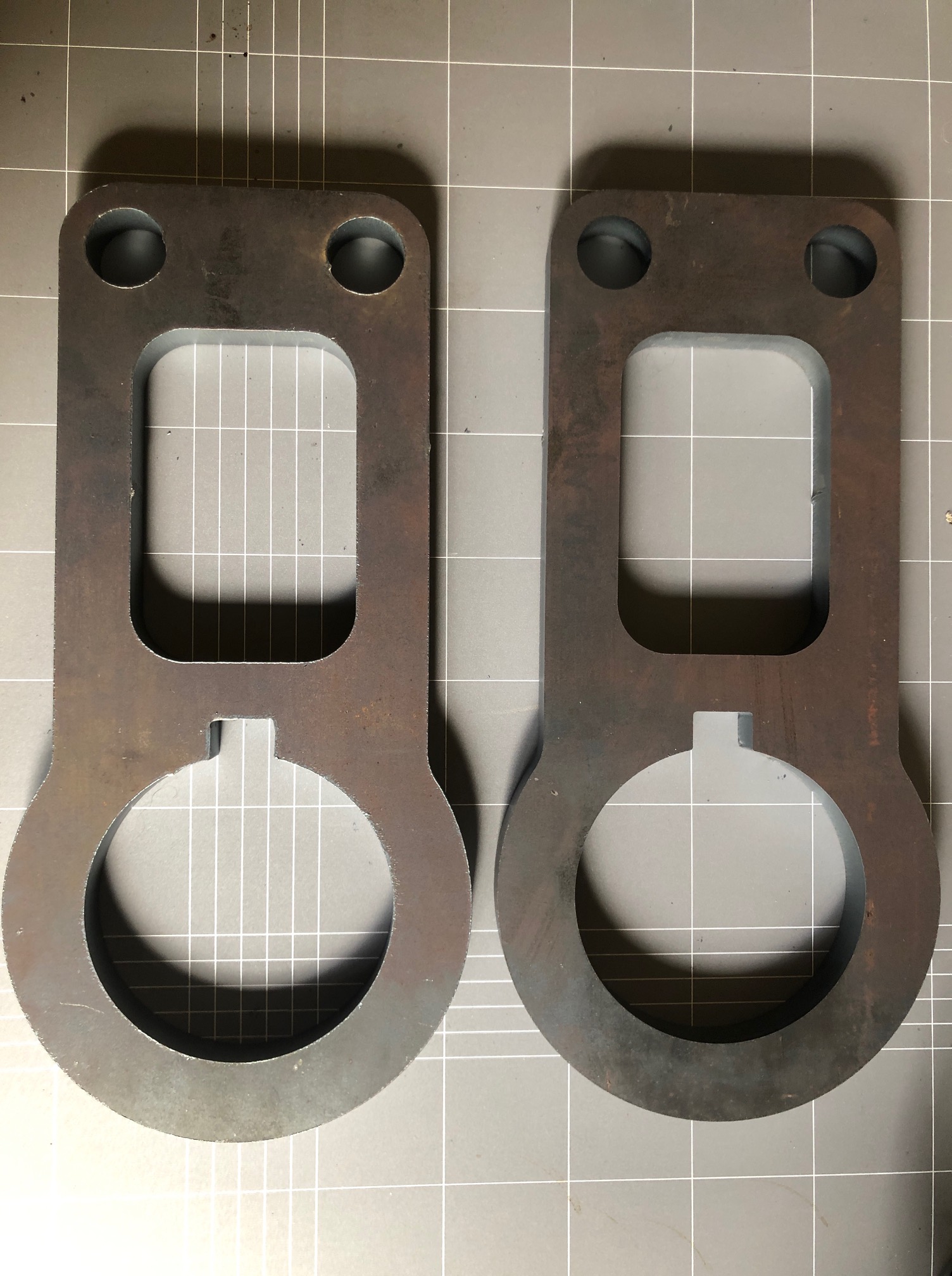
I used the opportunity to redesign the brackets to reduce their weight, as well fixing the mistake. The crucial dimensions are the diameters of the 3 circular holes, and the distance between the large hole (for the column) and the two small ones (for the linear stage rods). I specified the diameters to be 1 mm smaller than final dimensions to allow for final machining, to adjust for laser draught and laser cutting marks.
I was pleasantly surprised by the quality and accuracy of the laser cutting. There was no visible variation from 90 degrees cutting angle, and the dimensions were probably accurate enough to use with just a minimum of cleaning up. But I had to remove the 1mm machining allowance from the 3 holes.
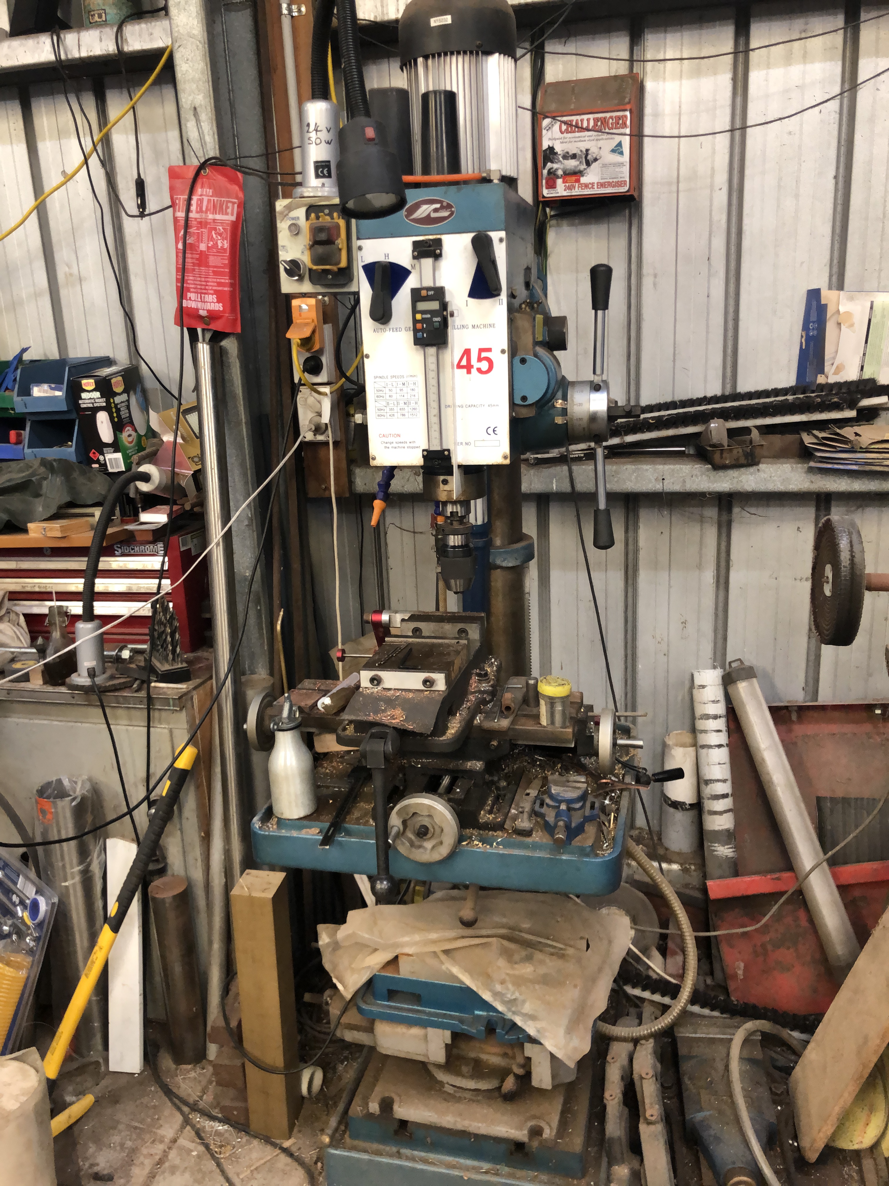
The setup on my 28 year old CNC mill. Note the spray coolant. 7mm depth of cut, 0.5mm side cut. All straight forward.
Then I milled some deep pockets for the cap screw heads, and drilled some 5mm very deep holes ready for cutting the screw threads for the 6mm cap screws.
Then disaster! Just finishing drilling the final 90mm deep hole, and the drill bit broke. With no part of the drill protruding. I had used coolant, and frequent withdrawals to clear swarf, but it was a long series drill bit, and I must have pushed it just a bit too hard. I could see the broken end of the bit about 20mm down the blind hole. No hope of getting it out that way…. too deep to weld and I do not have access to an EDM machine.
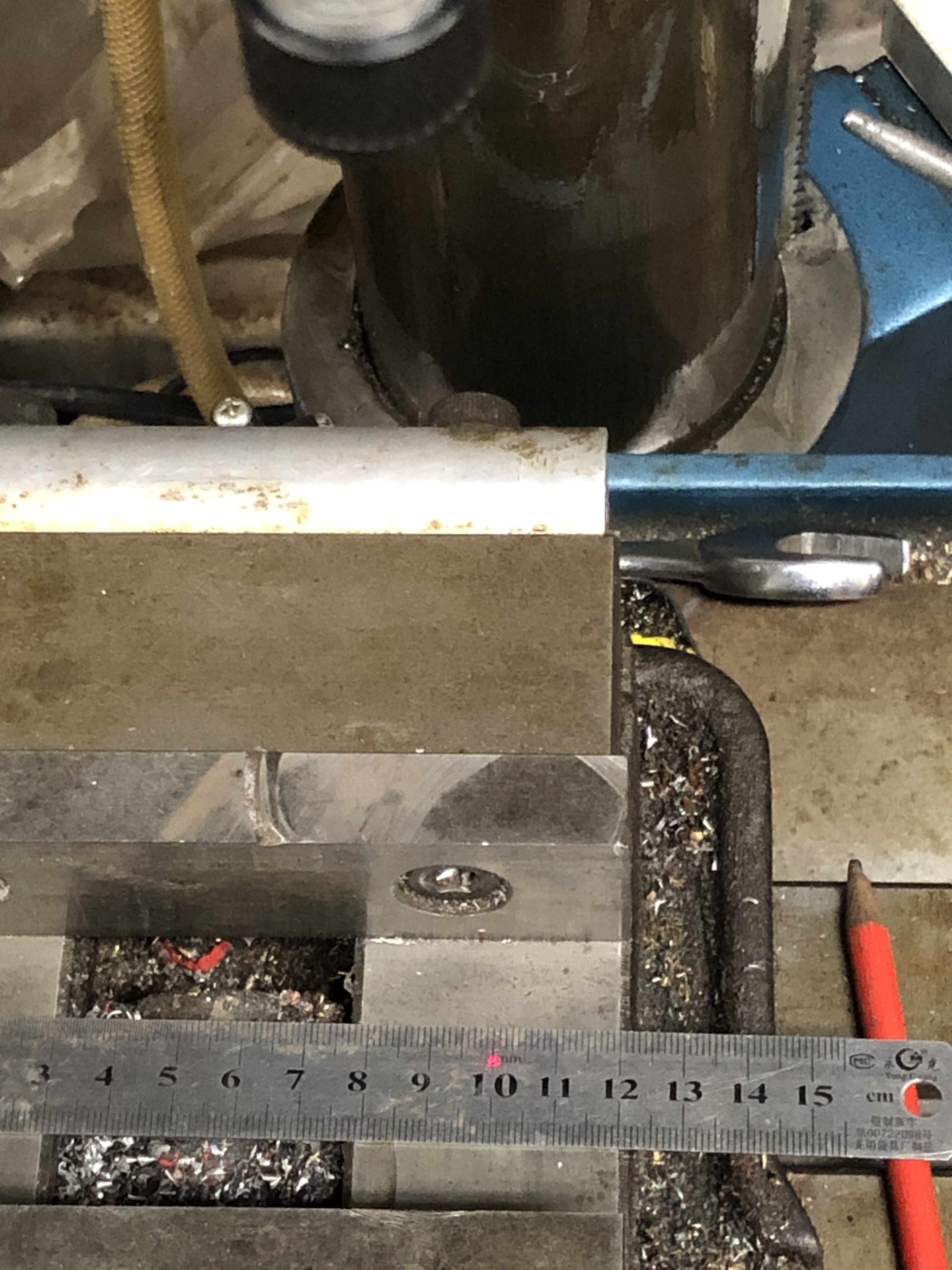
The big hole was to be cut into halves, then bolted together around the mill drill column.
Hmm, I wondered if I could bandsaw almost to the embedded high speed steel drill bit from 4 directions, without actually cutting into it then snap the steel halves apart, and maybe grab a protruding part of the drill bit? Worth a try? (If that did not work I might be able to break up the drill bit with an old carbide milling cutter. That has worked for me previously.)
Nothing to lose, and I could think of no other solutions, so that is what I did. Here I am cutting the part where the broken drill bit is in the lower part of the workpiece. I cut almost to the drill bit from 4 directions. I could have used an ultra thin cutting disk in an angle grinder, but decided to start with the bandsaw. Didn’t end up using an angle grinder.
Then held the piece in a strong vice, and ever so gently bent the pieces back and forth until I felt them snap apart.
Inspected the drill bit ends. The end in the through hole just fell out. In the blind hole there was a protrusion about 3 or 4mm long which I was able to grab with pliers. And glory be, I felt it move, and gently pulled and rotated and it came out! Lucky!
Then tested the parts on the mill drill column….
PERFECT FIT! Both halves clicked into position. (second half not shown in this photo). The rectangular cutout fits over the table elevating rack.
Then spent some time tapping the holes for the M6 cap screws. All good.
I need to drill, counterbore and tap holes in a similar fashion for the 30mm rods, but they should be much less deep (only 50mm). Then to repeat the entire exercise for the other bracket. Next workshop session. Then to set up the apparatus and measure how effective it is. It had better work. Next installment in a few days time.
I purchased this mill-drill quite a few years ago, and generally it has performed well. 6 spindle speeds, morse 4 taper, 3 auto feed speeds. I installed an X-Y table, a 6″ Vertex vice and the digital quill movement scale. All good.
But, the crank handle height adjustment for the head, and the table were both very heavy to use. And they are getting heavier as they get older.
As you can see, I tidied up the area especially for the photo.
So I installed a motorised raise and lowering mechanism for the work table. That was detailed in the post “Motorising a Mill Drill Table” Feb 2021. For a variable speed, reversing motor, I used an old Metabo drill, which has heaps of power for the job. I removed the crank handle, and installed a worm and gear in a 100x100x150mm box. It has worked very well, although I probably geared down too much, because even with the drill at full speed, it is slowish to raise and lower the heavy table.
BUT. The round column is very frustrating. When changing the height of the work table the XY position is not maintained, and that is a real pain when doing multiple tasks in a fixed XY position.
I tried attaching a laser light projected onto a vertical line on a nearby wall, and that worked in a fashion, but not reliably.
Then I used the gear rack to keep the table in a fixed vertical position, but that was also unsatisfactory, because the rack would flex and the position was not accurate enough.
So, I should have NOT purchased a round column mill drill to start with. And I would NEVER do so again. But I have put up with the limitation and have continued to think about possible fixes.
Then I saw this on Ebay. And thought. “I have a use for this!”
It is a linear stage. The 30mm polished steel rods are 800mm long, and the threaded block runs on precisely machined bushes, presumably bronze. The winding handle, 16mm x 2mm threaded rod, and revolution counter are of excellent quality, but will not be used. The item appears to have had little use. There were some extra bits attached which I will not use.
And here it is cramped into the position where it will be used…..
The Metabo drill is removeable, but basically lives in that position. The worm is visible in the photo. Normally the worm and gear casing has a metal cover.
I will make brackets to attach the bars to the round column in this position. I decided to attach the round bars rather than the end blocks to the brackets. The central block will be bolted to the worm and gear housing. I am confident that this setup will stop the work table from changing XY position when the height position is changed. It should not get in the way of drilling operations.
Drawing of the brackets. I intend to make them from some 20mm thick mild steel which I found in my workshop. I was hoping to get the brackets laser cut from aluminium, but was informed that there is a limit of 10mm with that metal. They could cut 20mm of steel, but I would need to add a machining and perpendicularity allowance of say 1mm. Still thinking about that possibility. Might be simpler to just mill the brackets myself. It is 352mm X 177mm X 20mm.
I will post some photos when it is finished. And some measurements of the rigidity of the setup.