johnsmachines

machines which I have made, am making, or intend to make, and some other stuff. If you find this site interesting, please leave a comment. I read every comment and respond to most. n.b. There is a list of my first 800 posts in my post of 17 June 2021, titled "800 Posts"

Tag: silver solder

Just how strong is a silver soldered join?

I bought some 6mm x 0.7mm brass strip to hold on wooden lagging on my 6″ vertical boiler.   Trouble was that I could find suppliers who had the strips only in 300mm (12″) lengths.  So I decided to join 2 of the strips to provide the 450mm lengths that I need.

I have made band saw blades with silver solder, quite succesfully, but the ends were scarfed so the join was over a 5mm or so length of the blade.

I wondered whether I could butt join the brass strips with silver solder, and if so, whether the join would be adequately strong.

IMG_6744.JPG

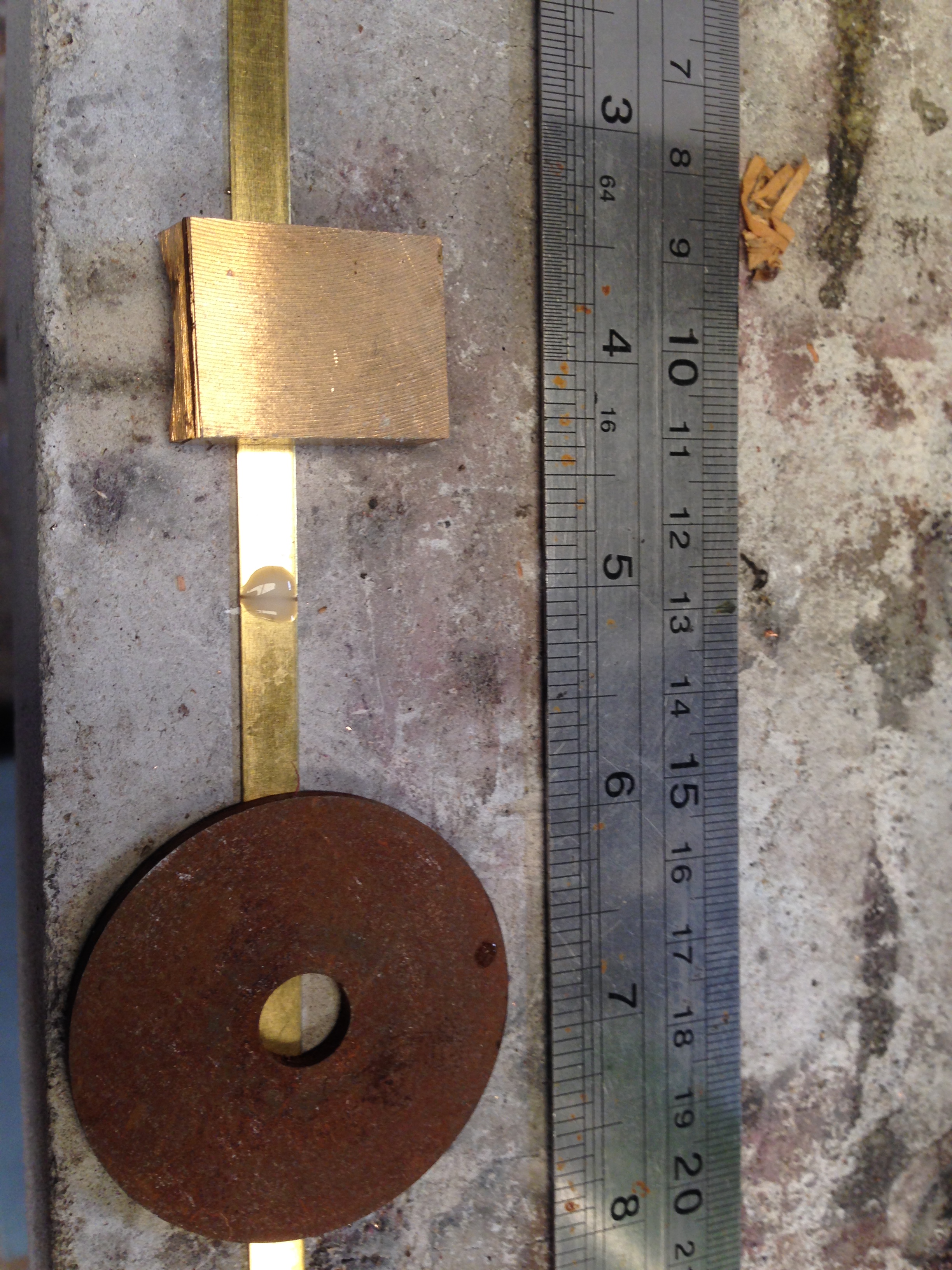
So here are the brass strips end to end, fluxed and weighed down so they do not move.

IMG_6745.JPG

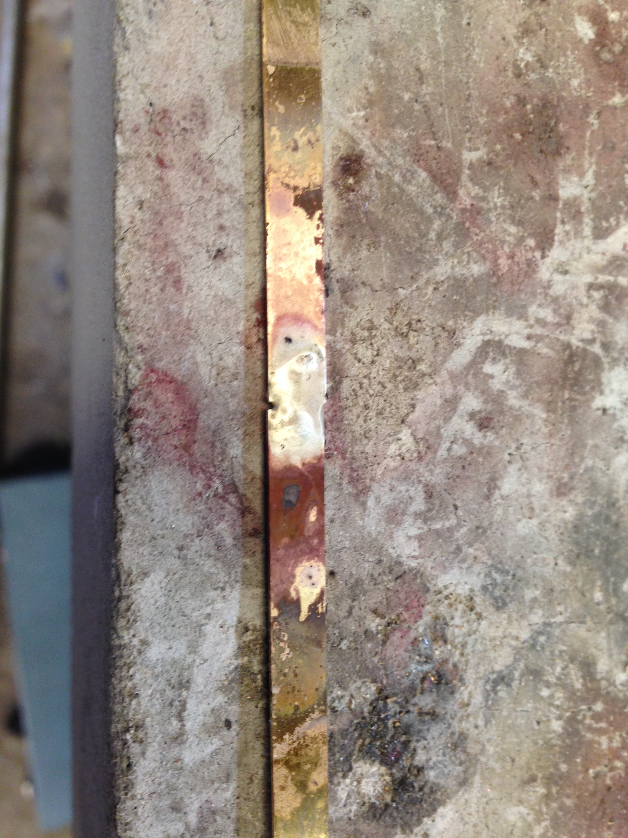
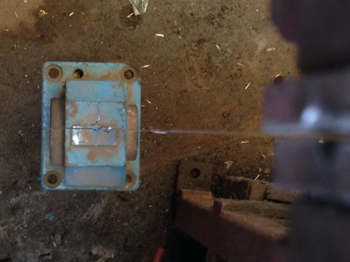
And here is the silver soldered join.  Not particularly neat, but OK for the purposes of the test.

IMG_6746.JPG

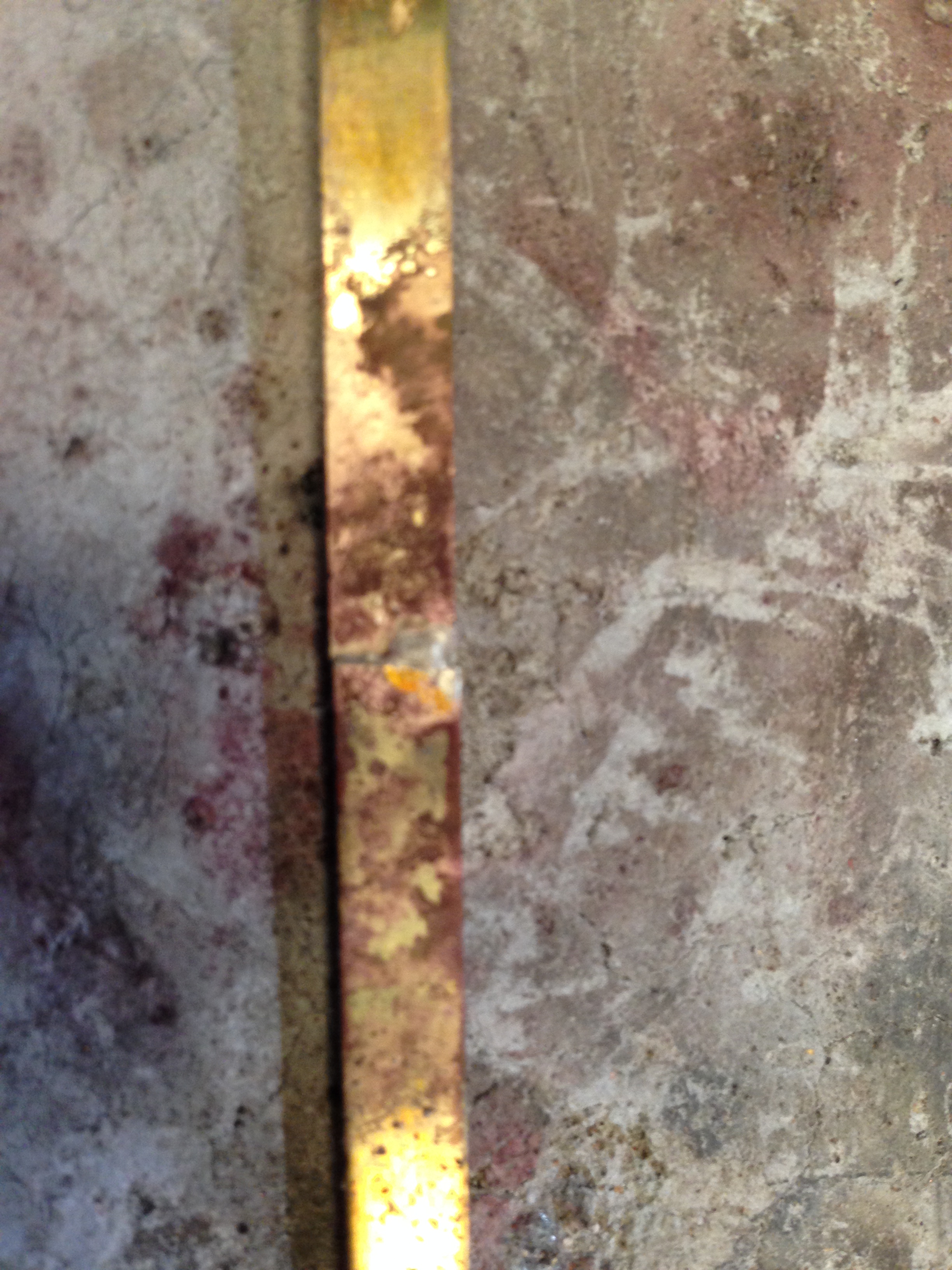
The other side.  As I said, not particularly neat. And I did not even bother with an acid soak.

IMG_6747.JPG

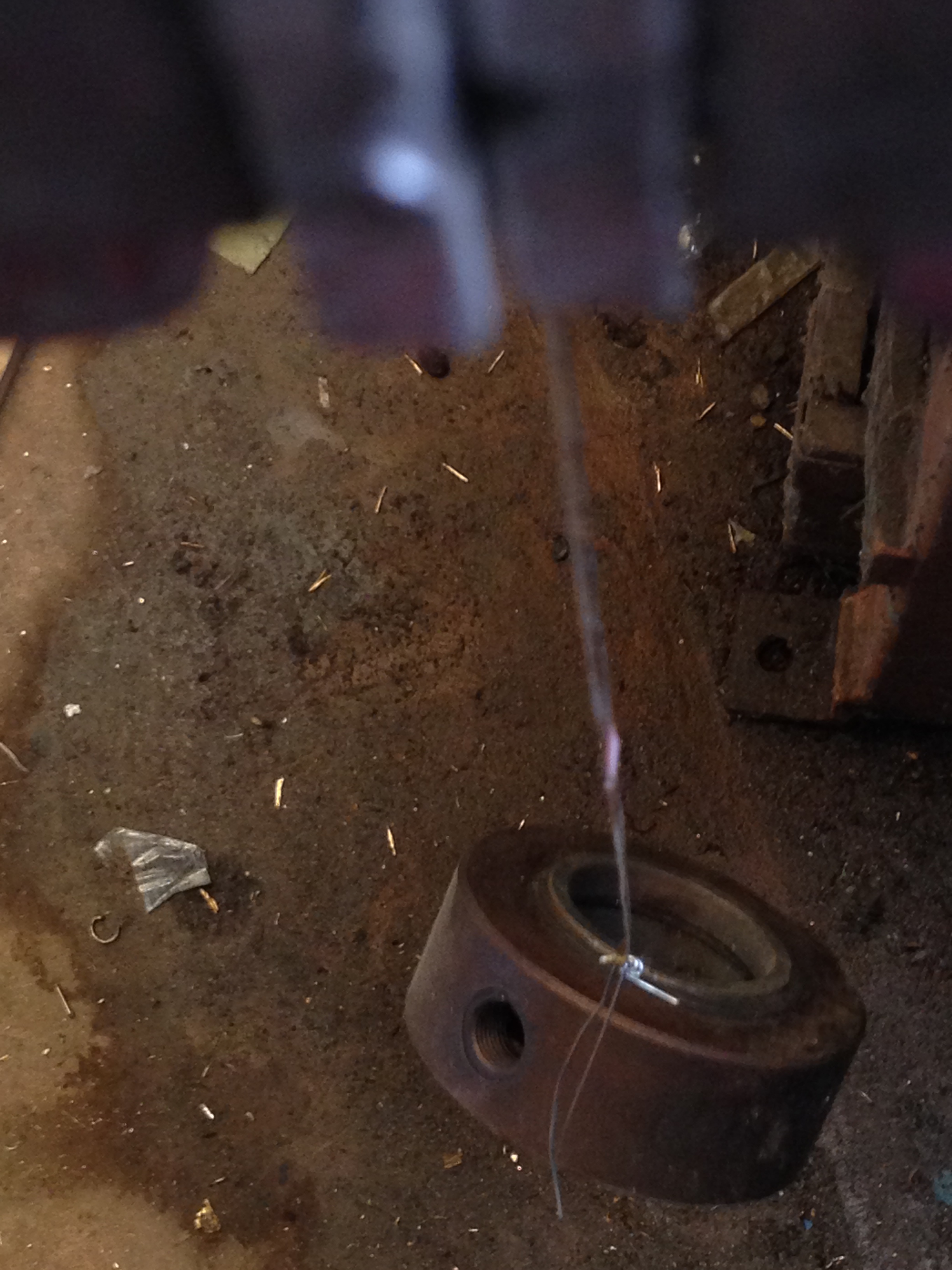
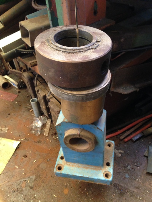
So I drilled a hole in the end of the joined strips, and wired on a hefty weight.  The top end was held in the vise.   Seemed OK so I increased the weights.

IMG_6748

IMG_6749

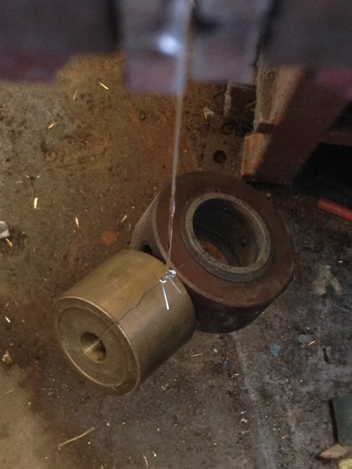
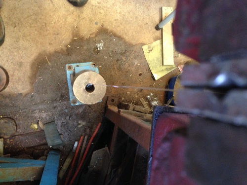
Looking down the strip from the vise.

IMG_6750

IMG_6752

By this stage I was standing back, expecting the soldered join to give way.  But it did not.  Hmm.   Must do a tidy up soon.
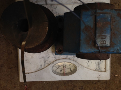
 

IMG_6753

21 kg, 46.3lbs.

At this point I stopped adding weights.  I think that the soldered join should hold the wooden strips to my model boiler!

Are you impressed?  I am.


Trevithick Dredger Engine-2 steps forward, 1 step back.

A few posts back I reported how I very cleverly silver soldered together some “sliced bread” bits of brass and bronze, because I did not have big enough material.

Then I spent a day machining the outlines, drilling the holes and finishing the parts.

Today I silver soldered the parts to the Trevithick boiler.  The joins in the material were so good they were invisible, and the fact that the joins were there did not enter my brain.

And this was the outcome.

IMG_6698

Before

IMG_6701.JPG

After

The beautiful silver soldered join melted as I attempted to silver solder the part to the boiler.  It has made the part unusable.

I will go through the exercise again, but next time I will bronze braze the join.  Bronze will not melt or let go with silver soldering temperatures.

I will try to not make this mistake again.  I try to not make the same mistake more than 3 or 4 times.

SILVER SOLDERING SUCCESS.

In the previous post I described my attempt at silver soldering the condenser unit.

The 29 joins on one end were quite water tight, but the other end leaked like a sieve.

I decided to try to fix the leaky end, by doing the following….

1. I shortened the copper tubes which were protruding more on the leaky end, thinking that the deep narrow spaces between the tubes might not have become hot enough during the soldering.

2. I used a Dremel to enlarge the spaces between the copper tubes.

3. I watered down the flux to make it more runny, in an attempt to get it into the narrow spaces.

4. I used a larger oxy-acetylene tip, to deliver more heat onto the job.  I think that maybe (as per reader John’s suggestion) I was getting intense heat at the soldering point, but maybe not enough into the base metal of the condenser.  The condenser is a thick brass, heavy object, and maybe, maybe it just was not hot enough.  With the bigger heat delivery, it did show the dull red heat which is recommended for silver soldering.  Also, I used a lower silver content rod (45%), again reader John’s suggestion, because it melts at lower temperature, and is less viscous, than the higher silver content rods.  Thanks John!

End result….

The condenser unit, after today's soldering fix.  Note: there are no air bubbles rising!  It is air-water tight, at atmospheric pressure.  That is enough, because it is a low pressure unit when in use.

The condenser unit, after today’s soldering fix. Note: there are no air bubbles rising! It is air-water tight, at atmospheric pressure, which is adequate, because it is a low pressure unit.IMG_2766 (1)Then I glued the end covers onto the unit, using Loctite, in preparation for the next step, which is drilling and tapping the holes for the BA7 bolts which will hold the end covers in place.

THE CONDENSER- not so easy afterall.

I had deferred making the steam passages (in the triple expansion steam engine), and moved sideways to an “easier” task, which was making the condenser unit.

It consists of a gunmetal box, with walls ~4mm thick, ends of 3mm brass, and 28 copper tubes soldered to the brass plates.  Plus end caps which required some milling and drilling ( see yesterday’s post).

I could not find my soft solder, so I used silver solder.  That was mistake 1. The heat source is an oxy actylene torch, and to keep the heat down I used a small tip. Mistake 2.  The end plates were first soldered (that is soddered if you live across the Pacific ocean) to the main body, and that seemed OK.

Then I fluxed the holes in the end plates, and fluxed the copper  tubes and positioned them into the end plates (mistake 3).  In view of what happened, I suspect that much of the flux was wiped off while pushing the tubes into position.

The water tubes silver soldered to the end plate.  The first end soldered, and it had multiple leaks...

The water tubes silver soldered to the end plate. The first end soldered, and it had multiple leaks…

The second end silver soldered, and it was perfect!  No leaks, looked neat.

The second end silver soldered, and it was perfect! No leaks, looked neat.

So, one end soldered without a hitch, and the other needs to be re-done.  Why?

3 possible reasons.

1. The copper tubes protruded further on the bad end, and it was more difficult to position the soldering rod in the in-between joins.

2. I used more heat on the good end.

3. It is likely that the flux was retained more on the good end.

So I am maintaining a well exercised tradition of learning from my mistakes.  I am sure that I have made mistakes 2 and 3 only a few times before.

So how to fix the leaky end??

1. Apply more flux and solder to the leaky bits?  Tried that.  Didn’t work.

2. Expand the copper tube ends with a tapered drift?  Tried that, and it helped, but still not enough.

3. Disassemble the leaky end by melting the silver solder and re-doing it?  After trying fix 2, I think that I have prevented this option.

4. Use soft solder to patch the leaks?  Not yet tried, but that is next.

If fix 4 does not work, I plan to remove and remake the tubes and end plates and re-solder the entire unit.

Make Your Own LONG SERIES TAP

My current project is a diversion from the triple expansion steam engine, which is about 33% completed.

I wanted to do some engraving on my CNC milling machine.  It is accurate enough in XYZ movements, but the spindle has a maximum RPM of approximately only 3000.  Engraving with a cutter with a tip of diameter 0.1 to 1 mm diameter really requires 10-20 thousand RPM.

I also have in mind making some wooden things using router bits, and they usually rotate at 12-26 thousand RPM.

I wondered about a manufacturers attachment for my mill but could find nothing.

So I decided to make my own.

I briefly considered attaching an electric  router to the mill, but since many projects require constant spindle work for several hours at a stretch, I decided that the spindle should have an inbuilt cooling system.

What I bought was a 2.2kW spindle, 3 phase, with a variable speed controller, giving an RPM range up to 24,000.  It is designed for liquid cooling, and can be used for long periods without overheating.

The spindle has an 80mm diameter, and I will attach it to the 110mm diameter quill on my milling machine.

So, I cut some holes in 16mm aluminium plate.


IMG_2713

The aluminium plate attaches to the milling machine quill, like this.


To clamp the plates to the quill, and to the spindle, I cut some slits into the holes in the plate, and drilled and tapped some 6mm holes. (done after the above photo was taken).

My problem was that my 6mm taps were all much too short for the job.
I went to my usual industrial tool supplier to buy some long series taps, only to be informed that long series taps are not kept in stock, and would take several days to arrive on special, and very expensive order. Long series taps apparently cost at least 3 times as much as conventional length taps.

Having had success at silver soldering band saw blades, I wondered whether I could add some length to a conventional tap by silver soldering some steel rod, end to end, to the tap.  It was also quite succesful.

Here is the setup for the soldering. (Sorry Americans, what you call soddering the rest of the English speaking world calls soldering).
IMG_2714The angle iron is held in a vice. The tap to be lengthened rests in the angle (after thorough cleaning and application of flux), and the rod likewise (in this case, a cap screw of the same diameter as the tap). The join is silver soldered in the usual manner.

This is what the lengthened taps look like.

I wondered whether the silver soldered join would be adequately strong for the tapping.  the tap was totally buried in the workpiece, and would have been irretrievable if the join had broken, and ruined the workpiece. So I was very cautious when doing the tapping.  Used a tapping oil, and backed the tap out of the workpiece every few turns for cleaning.

I wondered whether the silver soldered join would be adequately strong for the tapping. the tap was totally buried in the workpiece, and would have been irretrievable if the join had broken, and ruined the workpiece.
So I was very cautious when doing the tapping. Used a tapping oil, and backed the tap out of the workpiece every few turns for cleaning.  It worked fine.  It was a demonstration that silver solder is really very strong.

One advantage of using a cap screw for the lengthening rod was that the hex head proved ideal as an attachment for a tapping handle. The tapping handle being an Allen key.

I will post more pics of the engraving-routing spindle when it is finished.

ps. my expert friend Stuart T tells me that silver solder has a similar tensile strength to mild steel!