johnsmachines

machines which I have made, am making, or intend to make, and some other stuff. If you find this site interesting, please leave a comment. I read every comment and respond to most. n.b. There is a list of my first 800 posts in my post of 17 June 2021, titled "800 Posts"

Tag: Boxford 125 TCL.

Lathe Toolpost Milling attachment (CNC)


Although my recent posts indicate that I have spent  a fair amount of time recently on Google Earth Pro, I have also been busy in the workshop.  Mainly finishing the toolpost milling attachment for the Boxford CNC lathe, but also fiddling with the laser attachment for the CNC mill.  Neither of those projects is completely finished, but I thought that you might be interested in some progress photos.

IMG_8279

This is what the Boxford TCL125 CNC lathe now looks like from the front.  It is substantially modified from the original which I purchased 5 years ago.  To mention a few changes…..

the axis stepper motors are bigger and more powerful than the originals

the ball screws are now 10mm diameter, compared with the original 8mm

there are some adjustable axis limit switches

the 3 jaw chuck is replaced by an ER32 collet chuck

there is a removable toolpost milling attachment with ER 16 Collet chuck, with a speed controller, cables, and panic switch.

there is a removable safety screen (not seen in the photo)

And hidden in the electronics compartment….

IMG_8278.JPG

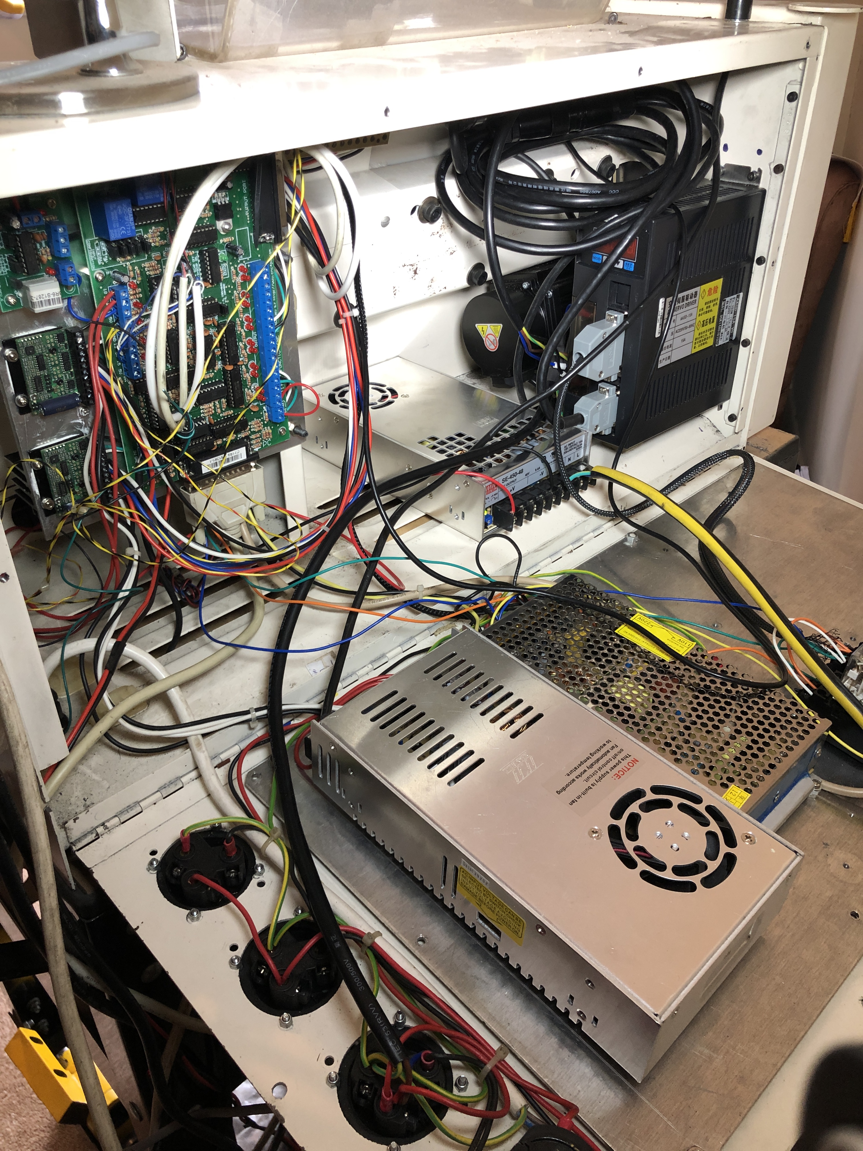
There is a 750 watt AC Servo spindle motor and controller (RHS, under the coiled cable)

The electronics have been replaced with a Mach3 compatible breakout board and associated peripherals.  Anyone with an original 1985 machine will hardly recognise these components.

And the software is now Mach3, running off an old Windows XP computer.  And using “Ezilathe” for most of the G coding, especially threading, and interpreting shapes which have been drawn as CAD dxf’s.

The new toolpost spindle works, but the software  needs a bit more fiddling to tie it into the CNC controls of the lathe.

The Boxford has provided an excellent base on which to make these changes, and I look forward to producing some videos soon of the renewed machine in action.


NEW SPINDLE MOTOR for CNC LATHE?

Now that I have replaced the stepper motors in the Boxford CNC lathe, (see “New steppers for an old CNC lathe”)  I am considering whether I might replace the spindle motor for the same reason…  that it has become less powerful due to the age of its permanent magnets.   Sometimes I am aware that it struggles to keep up the revs while cutting.

Watch the YouTube video about the next generation servo motors.  They use modern rare earth magnets.  They are powerful, compact and precise.  And not cheap.  Stuart T, who has the same Boxford CNC lathe as me, has suggested that these Clearpath motors would be suitable replacements for the ageing Boxford spindle motors .


SOFT JAWS FOR LATHE

I have recently made two sets of soft jaws, and tested them.  One set was successful and the other set was not.  Read on to see what made the difference.

The purpose of soft jaws is that the jaws themselves are turned to the exact size and shape of the workpiece,  and the workpiece should therefore be held perfectly concentrically.  It should be possible to remove the workpiece from the lathe, and to replace it accurately.  It should also be possible to hold very thin disks, which was what I aimed to do in this exercise.

The first set of soft jaws was made for a 200mm 3 jaw chuck.  The aluminium cylinders were bored to fit snugly over the last step of the jaws, and held in position with cap screws.   I cannot remember where the idea originated.

IMG_3360

These soft jaws fit onto existing jaws, and are held in place with cap screws.  Here shown clamped onto a brass cylinder, ready to have the rebates turned.

IMG_3361

Showing the turned rebates in the soft jaws, ready to accept the workpiece.

IMG_3362

The workpiece is a 3mm disk, 38mm diameter.  The rebate is only 0.5mm deep.

The method was successful, allowing the workpiece to be faced, but during a second pass, one of the soft jaws came loose, and the workpiece dropped out.

I suspect that the cap screws did not allow enough purchase on the hardened jaws of the chuck.  Also, the workpiece was positioned beyond the end of the chuck jaws, and it acted as a lever on the soft jaws, working them loose.

I think that this method would work if the workpiece was held closer to the face of the chuck.

The second set of soft jaws was made for an 80mm 3 jaw chuck on my Boxford CNC lathe.

IMG_3367

The aluminium soft jaws are bolted to purchased, non hardened, jaw bases which fit the chuck grooves and have teeth to engage the chuck scroll.  Here shown after turning the rebates ready to accept the workpiece.  The rebates were turned while the jaws were tightened against an appropriately sized cylinder.

IMG_3364

The workpiece held securely.  The face has been skimmed, and the edge bevelled.  The engraving was CNC’d on the mill, earlier.  Subsequent turning produces a very clean, sharply defined engraving.   The workpiece is held in a 1mm rebate.

It can argued that aluminium is not ideal for soft jaws, because it is too soft.   I do intend to make another set of soft jaws from mild steel, for use with steel workpieces, but I will continue using the aluminium soft jaws when machining soft metals such as brass.

And here is another idea which I spotted on you tube.  Not soft jaws, but soft covers.  Click on the arrow to watch the video.

BOXFORD CNC LATHE (3)

Some more photos of the Boxford, after the conversion.  Sounds like the Damascus Road doesn’t it.  Going CNC is almost an epiphany.

IMG_3342

This is the wireless MPG controller.  The lathe can be controlled from across the room, using the MPG and the wireless mouse and keyboard.  The MPG even has an Estop kill button, along with the one on the lathe.

IMG_3341

The new setup.  Normally the keyboard and mouse sit under the screen to avoid swarf.  Note the multitude of LED and halogen lights.  I need those these days.

IMG_3343.jpg

The old Dell sits underneath, along with other bits and pieces.  The trolley has been very useful, as the lathe is progressively expelled from different rooms by SWMBO.

IMG_3338.jpg

One drawer of tool holders, collets, inserts etc.  The other drawer is not so tidy.

IMG_3339.jpg

The Dickson toolpost, and Diamond tangential tool.

IMG_3340.jpg

The ER32 collet chuck.  Much more accurate than the Burnerd 3 jaw chuck.  The mounting plate and backing plate were made by me to a design by Stuart Tankard.

If this conversion is of interest to you, look out for a technical description of the process in an article by Stuart Tankard to be published next year in Australian Model Engineer.

BOXFORD CNC LATHE (2)

This is the list of components and prices (AUD 2013) which was required to update the electronics so the Boxford 125 TCL would run on Mach3 and Windows.

Breakout board  C11  $129

Index pulse board  C3  $26

Gecko stepper drivers G251  $68 x2

Relays, relay bases, parallel port cable, Estop button   ~$80

Power supply  $30

Wireless MPG   from China  Ebay  $129

Heat sinks and adhesive   $20

Other cables, connectors, power sockets  ~$100

PC (an old Dell, running XP Pro, perfectly adequate for Mach 3)   free

Flat screen     free,  wireless keyboard and mouse  free.

Support arm for Screen  $60

Trolley  $200

It all adds up to $AUD910.   Plus the original $1500 for the lathe.  That is pretty inexpensive for a quality CNC lathe.  I am told that the Boxford retailed for about $30,000 in 1985!

Some before and after photos of the conversion…


IMG_0985.jpg

The back of the lathe opened, showing the old electricals  The spindle motor is top right.


The electricals after the conversion.

The electricals after the conversion.  Some of the old components were retained.  The lights are on the breakout board. 

BOXFORD CNC LATHE

About 3 years ago I decided that I wanted to see what CNC was about.  I had read some beginners guides to CNC, and CNC programming, but it was obvious that I would need to buy a CNC machine and actually start machining if I was to make any real progress.

Initially I bought a second hand lathe which had been converted to CNC.  It was a Seig C3, and stepper motors had been installed on the lead screw and cross slide screw.  Some low end electronics connected to a PC, and the setup was controlled with Mach3.

Needless to say, this machine gave poor results.  Poor finish, and poor reproducibility of dimensions.  The lathe was low quality to start with, and the CNC components were low end.  I was inclined to blame the lack of ball screws, but in retrospect, that was only one of the many problems.  It did however give me a taste of the process of CNC programming, and finishing with a CNC turned item.  I also developed some familiarity with Mach 3, and became a licensed user of the excellent software.

IMG_1009

Seig C3 converted to CNC. Not up to scratch.


IMG_1011

Then I saw a Boxford CNC lathe, owned by a friend in my engineering club (GSMEE).  It was 30 years old, and had started life as a technical school teaching lathe.  The original electronics and operating system were based on a CPM computer, pre-dating Windows, even pre-dating DOS.  It ran on software which was loaded each session from a 5.25″ floppy disk, with a capacity of 180 kilobytes.

My friend had changed the operating system to  Windows and Mach 3.  That involved changing many of the electronic components in the lathe, and hooking up a PC.

The lathe was an English Boxford TCL 125.  The swing is only 125mm (62.5mm above the bed), and the maximum length which can be machined is also 125mm. The spindle is belt driven, and spindle speeds range up to 3000 rpm.  The tool post is a very nice quick change Dickson.  The spindle bore is 19mm.  The whole machine has a quality appearance and feel.   My friend was producing work with fine finishes, and consistent dimensions.

It was clearly a quality lathe, and I asked him if he was willing to sell.  The answer, not surprisingly, was no.  However, he did know of an identical machine which might be for sale.  To get on with this story, I did buy the second machine.  It had also been a training lathe in a technical school, and was 30 years old.  It was not running, but the owner said that it had been in use until recently.  Since I planned to replace most of the electronics I was not too concerned that it was not working.  My friend, Stuart, had indicated a willingness to manage the upgrade-conversion, which was just as well, because it really did require a level of expertise with electronics which I do not possess.  Stuart had been through the process, knew exactly what was required, and is indeed, an expert.

IMG_0990

Boxford 125 TCL.  The yellow item is the tailstock which swings up into position. 80mm Pratt Burnerd chuck.  The control panel lower right was removed and replaced with a wireless pendant control.

IMG_0989

It cost $AUD1500, which was a bit much, but the seller probably realised that I really wanted it, and priced it accordingly.  I took the lathe, and the computer, and the 5.25″ floppy drive, and 6 tool holders home.  I immediately put the computer and floppy drive on Ebay, and amazingly they sold for $AUD150 (to a  collector of obsolete computers I presume).

IMG_1053

This old CPM computer with a tiny memory originally ran the Boxford CNC lathe.

We collected the various new electronic components over the next few weeks.  I will list the components in the next post for your interest.  Total cost of these was approximately $AUD800.

Under Stuart’s direction I removed the obsolete electronics, then in two half day sessions he installed the new ones. After some adjustments in the electronics, and in Mach 3, it was up and running.

In the subsequent 2-3 years I have replaced the ball screws (probably unnecessarily), and increased the number of tool holders to 30, and installed an ER32 collet chuck, and soft jaws on the 3 jaw Pratt Burnerd.

I have made many items and become increasingly comfortable with Mach3.  I also use a very useful program called Ezilathe, which I will describe in a later post.


Boxford CNC lathe repair

I was having some difficulty seeing the work in progress in my Boxford 124TCL CNC lathe.  It reminded me of the situation before I had a cataract operation, but the cure in this case was rather easier.

The perspex cover was suffering from swarf blasting and had become opaque.  A lathe cataract you might say.

Rather than replacing the entire cover, I took the cheap option of cutting out most of the affected panel with a jig saw and screwing in a new piece.

It does not look quite as streamlined, but I can see the job in progress now.  And it will be easy to do a cataract extraction in future.

IMG_2441

TNC Lathe renovation 2

Some progress on the little lathe.

A complete disassembly, and separation of the parts to be repainted.

Some unwanted holes were filled with steel putty (similar to JB Weld), and filed flat after hardening.

Then further filing of the parts, a soaking in degreaser, and then a wipe over with acetone.

Then a coat of undercoat, from a spray can.

IMG_2435IMG_2439

Can hardly see the repair

Can hardly see the repaired holes through the undercoat.

Making the larger handle, the one for the leadscrew was a learning exercise.  I planned it in brass, with a counterweight to the handle.  Drew it up on CAD, then tried to make it using the Boxford CNC.  The end result is not perfect, but it will do.

IMG_2443I discovered that it is quite difficult to turn complete balls on each end and avoid chatter.  I used a carbide cutter.  Perhaps HSS would have worked better.

First result goes in the rubbish bin.

IMG_2437

Actually it will go into the odd brass bits bin in case it can be used for something.

I finally turned one end, then made a split collet, and turned the other end.  All done using CNC.

IMG_2436

Did not entirely eliminate the chatter.

IMG_2438

The partly completed workpiece, held in a taper split collet, which was held in an ER collet, which was held in my home made collet chuck.

IMG_2444

It will just have to do.

DIVERSION

I have heard that the castings for the triple expansion marine engine will be arriving in the next week or so. That is good news after waiting since the order was placed in January.
In the meantime, I have bought some castings and partly made components for a Burrell Traction Engine. It is 1.5″ scale, and I obtained some 1.5″ plans from EJ Winter for the Burrell. Unfortunately, one mans’ 1.5″ is anothers’ 1.45″ and the plans are not exactly correct for the castings! What would have been a difficult build, has turned into a very difficult build. So I have put it aside and will tackle it gradually. The plans will be some use, but as well as the difference in scale, there are differences in the designs. So I will have to make it up as I go, to a considerable extent.
My metal working club has promoted a competition for 2014, and it appeared to be a fairly simple build, so that is what I am currently machining. See the progress in the photos below. It is a Stirling heat engine, designed by J Ridders. You can see one working on the Ridders web site http://heetgasmodelbouw.ridders.nu

IMG_1989

IMG_1990

IMG_1991

Almost finished stand for the cylinder fork.

Almost finished stand for the cylinder fork.

IMG_1993

Components made so far

Components made so far

The spirit burner, almost finished.  Copper and brass,  silver soldered.

The spirit burner, almost finished. Copper and brass, silver soldered.

Stirling "Bobber" plans

Stirling “Bobber” plans

Steam Cock and valve. Making the handle.


The steam control cock and butterfly valve.

The steam control cock and butterfly valve.

The brass and redgum blank joined with M3 threaded rod

The brass and redgum blank joined with M3 threaded rod

The brass-wood handle after turning

The brass-wood handle after turning

Milling the squared section

Milling the squared section

Drilling the square hole

Drilling the square hole

Filing the square hole corners.  (you didn't really believe that iI would drill a square hole did you?)

Filing the square hole corners. (you didn’t really believe that I would drill a square hole did you?)

Finished handle
Finished handle