johnsmachines

machines which I have made, am making, or intend to make, and some other stuff. If you find this site interesting, please leave a comment. I read every comment and respond to most. n.b. There is a list of my first 800 posts in my post of 17 June 2021, titled "800 Posts"

Tag: Fowler

New Mechanical Oiler for Fowler Traction Engine

The oiler on my 3″ Fowler compound traction engine was working only intermittently.  I bought a new Foster Lincoln oiler, and today installed it.

The old oiler flange which attaches to the engine, was flexing, so I made a new one from 3mm stainless steel plate.  That will not flex.

The oiler is powered off the high pressure cylinder valve rod.  Different geometry was required.  I could have modified the original valve rod clamp and arm, but just in case I wanted to revert to the old configuration I made a new clamp and arm.

It all fitted nicely and the ratchet wheel clicked over as required when the engine was turned over.  So I completed the installation by silver soldering an oil delivery pipe to the valve chest.

Fowler pistons oiler safety valves.JPG

The original oiler

IMG_5992.JPG

The new oiler

IMG_5993.JPG

Hmm…  that delivery pipe needs to be straightened.  Sacks of coal in the background.

Traction Engine Oiler

The oiler which had been made for the 3″ Fowler compound steam engine looked OK, with a nice rounded brass cap, but despite various adjustments I could not induce it to work reliably.  The pawls were very thin brass, not hardened steel, and the supporting bracket was very thin sheet steel which had little resistance to flexing.

I decided to replace the oiler.   I could have made one from the engine plans, but when I saw some photos of these Foster Lincoln oilers on scale model traction engines, I decided to purchase.

FullSizeRender.jpg

The one which I purchased was designed for a 4″ scale traction engine, bigger than my 3″ Fowler, but the external dimensions were similar to those specified on the Fowler plans, and the Fowler is a 2 cylinder engine.  So I decided to go “too big” than risk “too small”.

It arrived by mail today, from the U.K.   Cost £116 + £10 p&p from “Live Steam Models”.  Not cheap, but the quality appears to be excellent.   Heavy brass body, hardened steel pawls and ratchet wheel, stainless steel water drain, and a powerful spring operated pump.  The lid closes with good tight fit.  Some filing will be required on a cut edge of the lid, but no big deal.

IMG_5947.JPG

The pump in the oil cavity.

IMG_5950.JPG

TRACTION ENGINE STUFF

My brother and I visited a well known local machinery enthusiast.  Some of my readers might be interested in the photos.

IMG_5927.JPG

An excavator from the 1940’s, due for restoration.

IMG_5926.JPG

Said to be incredibly noisy and heavy for the operator.

IMG_5928.JPG

Excavator diesel engine works.


My miniature Fowler traction engine does not have a steam injector and I am considering installing one.  So here are photos from a full size Fowler, and another from a  Ransomes traction engine.

IMG_5907.JPG

Fowler R3 steam injector, located near the bottom of the rear water tank.

IMG_5916.JPG

Ransomes injector located similarly.

IMG_5906.JPG

A pin, for a pin, for a pin, for a winch. (Fowler traction engine)

IMG_5917.JPG

Why do the boiler stays have holes bored into them?  When a stay breaks it usually occurs on the inside of the boiler.  The break can be undetected.  If there are blind holes bored like this, steam will escape through the hole if there is a fracture, revealing the problem.

IMG_5912.JPG

The countersink on the stay holes here is decorative only, serves no useful purpose, and probably weakens the stay.   The differential gear on the left is very worn, but still useable.


IMG_5925.JPG

Ransomes traction engine on the left, and Fowler R3 heavy haulage engine on the right.  2 tonne rear wheel removed and chained to the post, while transmission gears are being remachined.

IMG_5910.JPG

The ash pan from the Fowler R3, after 4 days of continuous steaming at the Geelong Show.  Of interest to me, because on my 3″ scale (1:4) Fowler the ash pan has been almost exactly scaled and I suspect that it would benefit from a redesign.

IMG_5904.JPG

Kelly single cylinder traction engine.  Working condition.

IMG_5905.JPG

Kelly engine.  Everything visible.  Note the very useful steam dome.

IMG_5909.JPG

Fowler R3 nameplate.  I can see something similar appearing on my 3″ Fowler.

IMG_5921.JPG

Front wheel on the Ransomes traction engine.  Both front wheels were torn off in an accident in 1920.  Going down a long steep grade at Shelford, Victoria, there was insufficient steam pressure to brake the traction engine towing a heavy load, so the driver deliverately crashed the engine into the road cutting, at considerable speed.  It was succesfully repaired by a blacksmith.  The driver survived.

IMG_5919.JPG

IMG_5920.JPG

The Ransomes engine.  The “Rolls Royce” of traction engines, according to the owner. (But I suspect that he prefers his Fowler).

So, I hope that you found these pics interesting.  John.

Traction Engine Safety Valves

Some videos of showing the safety valves functioning, boiler pressures etc.in my Fowler 3″ scale R3 traction engine.

new safeties

Warrick Sandberg safety valves.  Substantially bigger holes.  “pop” action.

And one of the Fowler being driven by my brother.

Traction Engine. New Parts.

Another quickie.

The new safety valves arrived today.  Warrick Sandberg valves.  I will install them later this week, and fire up the Fowler R3.

IMG_5873

The old safety valves.  Not up to the job.

new safeties.JPG

The new safety valves.  about the same dimensions but the exit holes are bigger and the spring tension is adjustable and lockable.  

And another thing.  I noticed this label near the pressure gauge of the full size Fowler R3.

IMG_5772

So I made this one today.  Slightly modified the information to suit my 3″ scale Fowler.

working pressure new.JPG

My enamelling technique could improve, but it will do.

The Boiler Inspector.

Today I loaded the Fowler 3R traction engine onto its trailer and drove to Werribee, to have an official inspection of the boiler.

This is not a legal requirement, because I can operate my traction engine  whenever I please on my own property.  But all model engineering Clubs and Societies require a current certificate before they will permit steam engines to be operated at their meetings.

The maker of my traction engine had the boiler inspected and passed about 18 months ago, but that certificate has now expired.  So it needed re-certification.

The original test pumped water into the boiler at double the maximum operating pressure to test the boiler for leaks and distortion.  The boiler is actually designed to withstand pressures of EIGHT times maximum operating pressure, so the safety factor is reassuring.

But, boiler explosions are horrific, so the caution is understandable.

My boiler is made of copper, thus avoiding the problem of steel boilers which gradually becomed thinned by rust.   And my boiler seams were joined by silver soldering, which, if expertly done is as strong as the parent metal.  As a matter of interest, the maker of my boiler told me that he had used $AUD1000 of silver solder in the construction of the boiler decades ago!

The test today involved pumping water into the boiler at 25% above maximum operating pressure, and holding it there for 20 minutes, checking the boiler for leaks and distortion.  It passed that test without problem.

The next test was for the functioning of the safety valves.  I had cleaned them and replaced the balls and polished the seats, and I had seen them blowing off when the pressure was above 100psi, so I was fairly confident that the certification was “in the bag”.

So the fire was lit, and after some coaxing because I had stupidly forgotten to bring the chimney blower,  the  steam pressure was raised to 100psi.  The safety valves started venting off.  But, the test is fairly demanding.  The fire was roaring, the steam blower was turned on full, and the pressure continued to rise.  It rose to 120psi which fails the test because the safety valves should have released enough steam to keep the boiler pressure at 100 psi or 110psi maximum..  Some adjustments to the safety valves did not fix the problem.

Some machining will be required to fix the valves, but after consideration I have ordered brand new safety valves and the test will be re-done when the new ones are fitted.

The boiler inspector was quite particular and proper, and very helpful.  I am grateful that this safety issue was detected, and I totally agree that it has to be fixed.  Thinking back to my problem of about 1 month ago, when I “dropped the fire”, (see “Holes in Swiss Cheese) I now believe that the problem was partly caused by the inadequate safety valves.

Add one more hole to the Swiss Cheese theory of disasters.

IMG_5873.JPG

The inadequate safety valves.

IMG_5872

The safety valves AND the oiler were replaced.

The new safety valves arrived today.  Warrick Sandberg valves.  I will install them later this week, and fire up the Fowler R3.

IMG_5873

The old safety valves.  Not up to the job.

new safeties.JPG

The new safety valves.  about the same dimensions but the exit holes are bigger and the spring tension is adjustable and lockable.  

And another thing.  I noticed this label near the pressure gauge of the full size Fowler R3.

IMG_5772

So I made this one today.  Slightly modified the information to suit my 3″ scale Fowler.

working pressure new.JPG

My enamelling technique could improve, but it will do.

FOWLER R3 TRACTION ENGINE

Start of the parade of tractors at the Geelong Show.   Graeme and John driving the Fowler R3.   Video by Stuart.


Error
This video doesn’t exist

TRACTION ENGINE (update)

Finally found someone with enough speed to upload a video.  Stuart filming.

Shot near Geelong.  Tom driving.  SWMBO and me on the kids’ cart.  Ange supervising.   The safety valves blowing off some steam.  Not much smoke from the Welsh steaming coal.


Holes in Swiss Cheese.

IMG_5479

I decided that the time was right for me to fire up the traction engine.  I had seen the maker do it once, and another local expert do it again.  And I thought that I had taken in the essential steps and safety features.

So I wheeled the engine out of the shed onto a piece of thick plywood.  Filled all of the bearings with oil, pumped water into the boiler, opened the cylinder cocks, and lit the fire with kerosene soaked dry wood.   Then shovelled in some Welsh steaming coal.  The fire started up well, and within 15 minutes the pressure started to rise.

At 40psi I removed the fan on the funnel, and the pressure continued to rise.

At 60 psi I started the engine.  It turned over very nicely, and continued to run.  All good.

The pressure continued to rise, 80-90-100.   At 100 psi the safety valves started to vent, as expected, but the pressure continued to rise.   110-120 psi.

120 psi is well above expected pressure.  The safety valves continued to vent, but not quickly enough.  I decided that the fire was too hot.  What I did not realise, was that the cam which drives the water pump was slipping on its shaft.  The water pump was not functioning.   I could see that the boiler water level needed topping up, so I turned on the 160psi electric pump.  It did not seem to be working.  In retrospect, the nominal 160psi electric water pump spec is optimistic.  I used the hand pump.  There was some resistance which is good, but I could not see the water level rising.

To cut a long story short, I dropped the fire.  It was all very scary.  “Dropping the fire” involves pulling out 3 long metal pins which hold the fire pan in place.  The pan drops to the ground, spilling the burning coal beneath the traction engine.

Of course the pins, and the pan are hot hot.  And the burning coals are even hotter.

Then I could smell burning rubber.  Oh shit!  A piece of coal against one of the solid rubber tyres.  Panic pushed the engine a few feet away from the pile of burning coals, trying not to stand in them.   Stamped out the bit of plywood which had caught fire.  (I had rolled the engine onto a piece of thick plywood because it is difficult to roll it on the thick gravel which surrounds my shed.)

Steam engines are not for the faint hearted it seems.  Nor for the ignorant amateur.  I have a learning curve looming.

I had noted that quite a few nuts and other fasteners were not very tight.  I can only speculate about the reason for that, but the water pump failure due to a loose connection was a bit concerning.  So I have decided to disassemble the entire engine, check everything and reassemble it.  Should be interesting.

Considering the causes for this near disaster, I list the following in no particular order….

Shaft driven water pump failure due to an unexpected loose connection

Electric water pump not working at specification (to be confirmed)

Operator inexperience (unsure about hand pump pressures and valve positions, no experience in dropping the fire, furnace fire possibly too fierce, insuffient practice in emergency steps.  In retrospect I should have closed the fire damper, opened the fire door, and stopped the engine turning, and maybe used a fire extinguisher).

In medicine, disastrous outcomes are usually caused by multiple small mistakes, rather than a single big mistake.  “Holes lining up in the Swiss Cheese”  theory.

It seems that Swiss Cheese also occurs in steam engines.

p.s.  Note added 8 Nov 2017,  6 weeks later.  See my blog “The Boiler Inspector”.  It seems likely that the safety valves were not up to the job of venting adequate steam with a vigorous fire.  Another hole in the Swiss Cheese lined up.

Compound Traction Engine

A few of my readers will have no idea what a “traction engine” is, much less a “compound traction engine”.

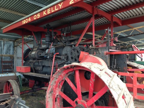
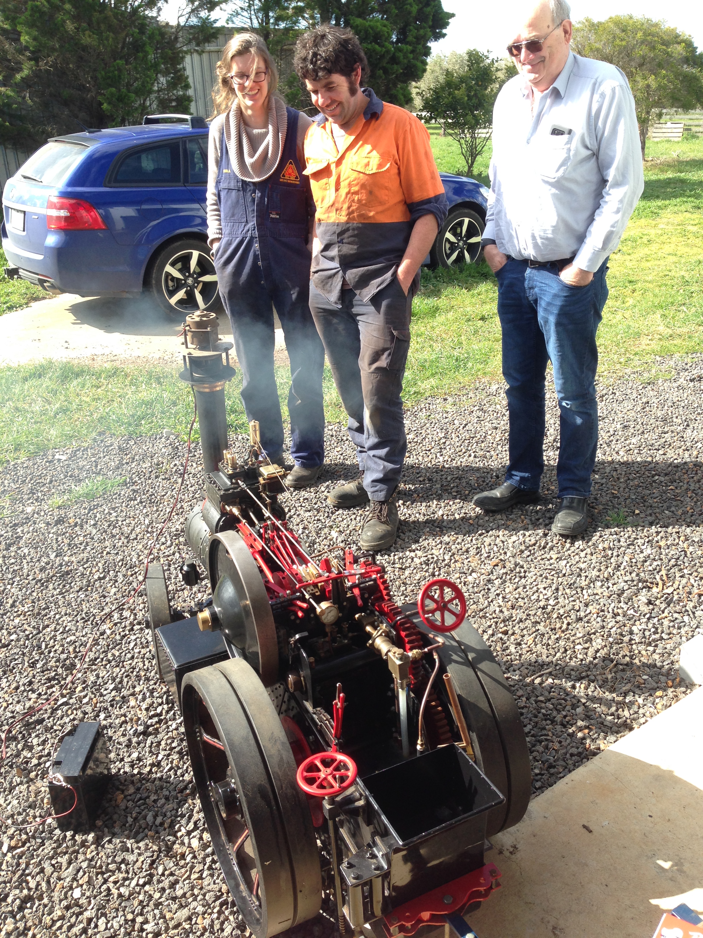
I have recently bought one of these machines, so here it is….

IMG_5498.JPG

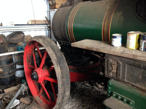
To be accurate, it is a miniature traction engine.  1/4 size.  A full size one would weigh between 14-18 tons, and a bit beyond what SWMBO would have agreed to me spending.  I see ads in the English sites offering them for between 250 and 400 thousand pounds.

This one weighs about 250kg, and it cost me a bit less than a full size one.

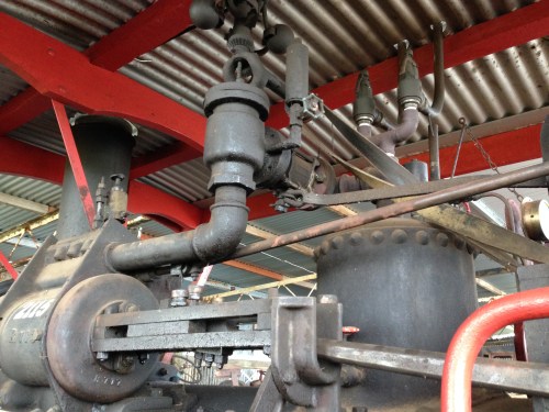
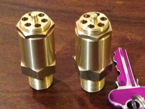
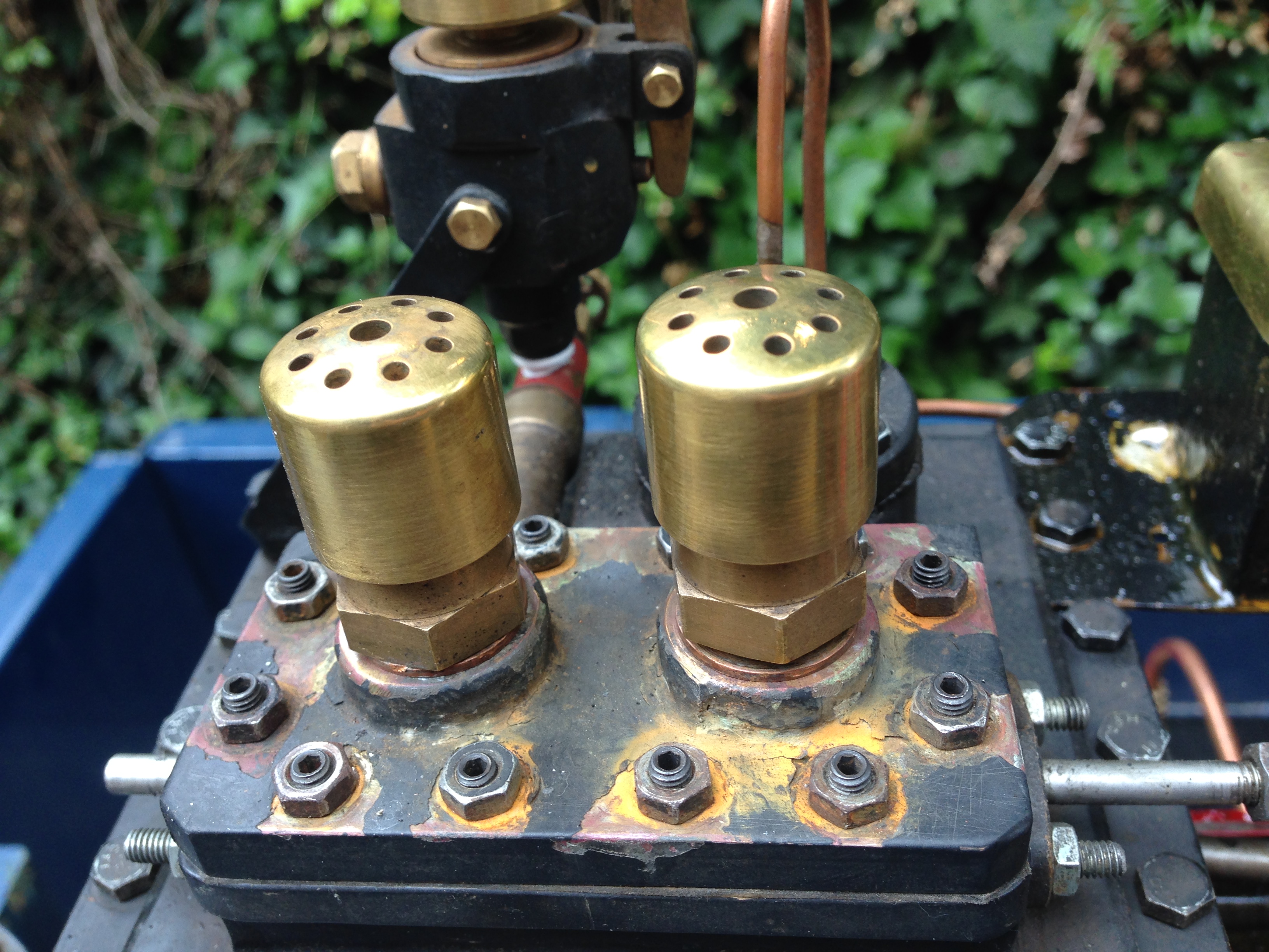
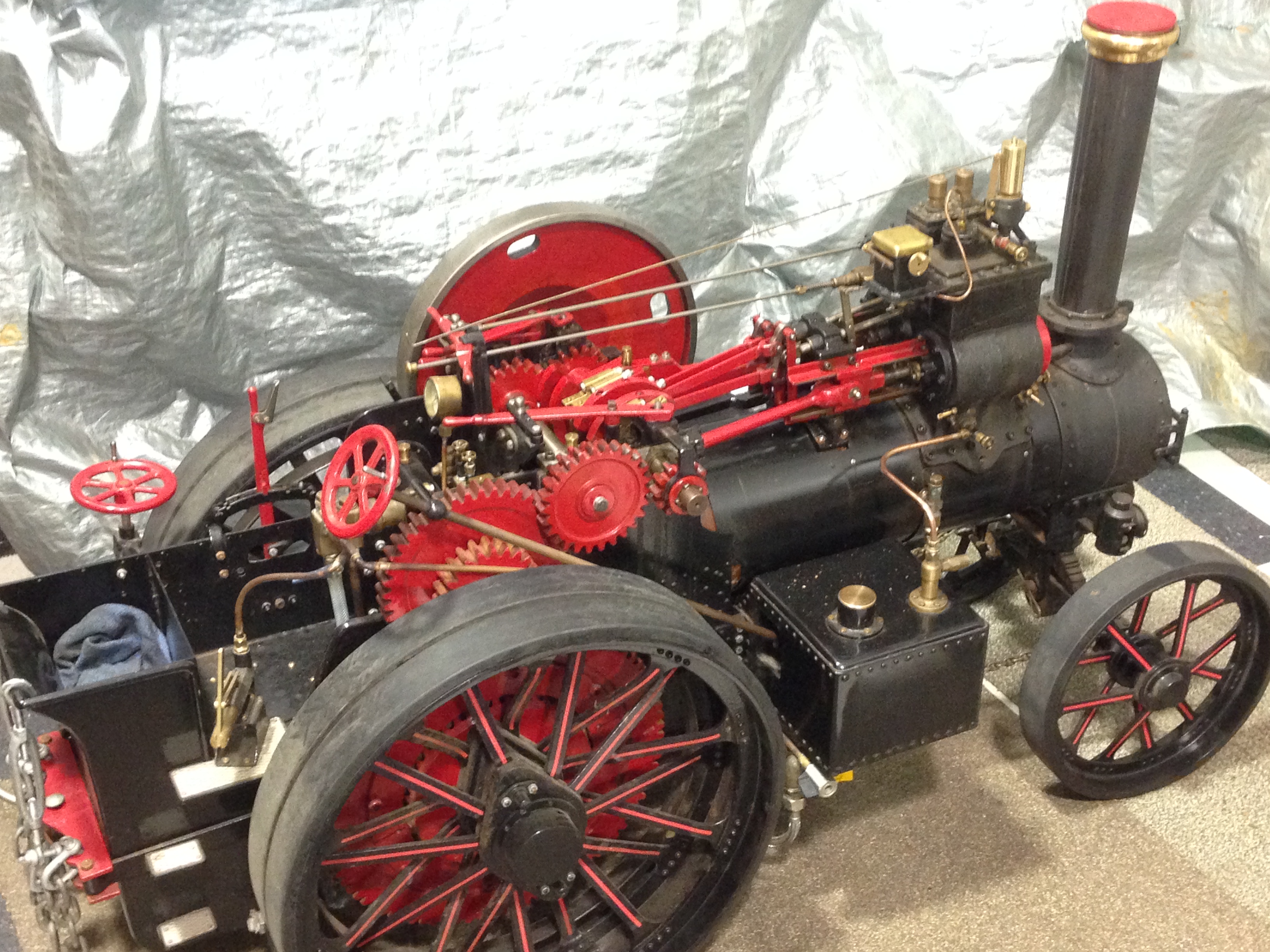
It is powered by lighting a coal fire in its belly, and producing steam.  The engine sits on top of the boiler.  You can see the cylinders, connecting rods, crankshaft and gears in plain view.   The steam is under a pressure of 100lbs per square inch.   It passes through the high presssure cylinder (the small one) then through the low pressure cylinder to convert the heat energy of the coal into kinetic energy of motion.   The fact that the two cylinders are powered by the same bit of steam is the reason it is called a “compound” steam engine.

Steam traction engines were the predecessors of modern diesel tractors.

As road locomotives, they pulled loads of many tons, at low speeds, from 1869 to the end of WW2.  This one was a scale model of a road loco of circa 1918.  Other types were used on farms as tractors (not terribly effectively, because of their weight), in saw mills to power the saws, and as stationary engines to power some factories.

Rather surpisingly, they are a quiet machine in comparison to more modern diesel and petrol powered ones.  They sound a bit like a steam train, puffing and chuffing along.  I fine the sound is very appealing.  I also like the exposed mechanicals.

The coal smoke is not quite so pleasant, but the Welsh steaming coal which I am using, produces very little visible smoke.   Most of the white stuff which is seen is esacaping or exhausted steam which has been cooled to become water vapour.   Steam, as I have discovered, is invisible.

So back to my traction engine….    It was made by a gentleman in Adelaide, commencing in 1984, and completed in 2016.   He also made quite a few steam train engines and traction engines over the same years.  He told me that the compound engine was difficult to make due to its complexity, and the tight squeeze of all of the components.

IMG_5503.JPG

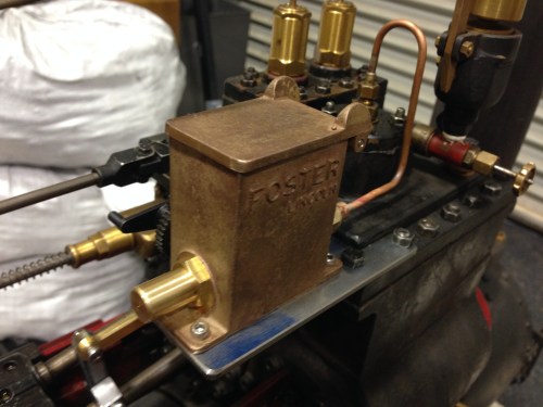
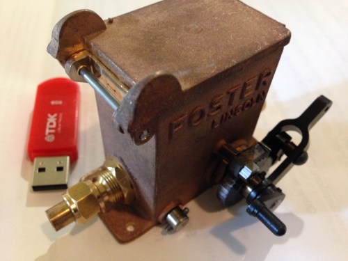
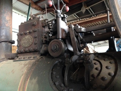
The square box with the brass lid is the mechanical lubricator,

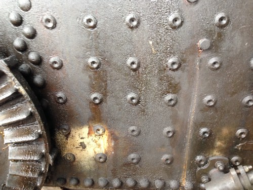
The boiler is constructed from copper sheet, 4mm thick, riveted and silver soldered.    It has been tested, and certified to 100psi.  Re-certification is due, and is planned to be tested again in a couple of weeks.

I have found a few issues with the engine, and am gradually attending to those issues.   The piston rod glands, valve chest, main throttle, and starting valve were leaking steam.  Those leaks have been reduced to a level that is acceptable.

One of the big ends is noisy.  I noticed that the plans called for adjustable wedges, and they have not been used.  So at some stage I plan to make them and install them.  That should tighten up the noisy bearing.  The valve eccentric straps are a bit loose, with noticeable movement, but they should be fairly simple to tighten.

The mechanical lubricator is not working.  I have cleaned and adjusted it, but to no avail.  There does not seem to be enough movement in the driving arm to click the gear over.  Might need a re-design or a new lubricator altogether.

Some of the water supply pipes are modern flexible types and look totally wrong, so they will be replaced with rigid copper pipes.

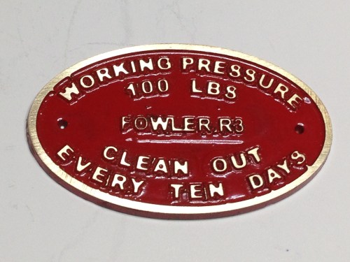
The painted colours are appropriate for a working road machine, but I am planning a more fancy appearance with brass belly strips, polished steel cylinder covers, some pin striping, and a name plate.   Also a Fowler coat of arms.  (It is a Fowler Class R3).

Still contemplating the name.  Traction engines seem to be named after girlfriends wives or mistresses, famous people, Lords and Earls.   There is a nice movie from the 1960’s about a traction engine named “The Iron Maiden”.  Its rival was named “England Expects”, a name which resonates.   I have long been an admirer of Sir John Monash, so that is quite a possibility.  Monash was the leader of the Australian Army 1916-18, and he was so effective that the British Prime Minister of the day said that WW1 would have been a year shorter if Monash had led the allied forces.  Monash was also my university.  And we share first names.  But still considering.

So you can see that I intend to place my own stamp on this machine, and have lots of interest and fun doing it.

IMG_5534.JPG

Boiler fire started, extractor fan on the funnel to increase the draft through the firebox, Ange, Tom and Stuart waiting for steam pressure to rise.

I attempted to upload a 2 minute video, but just too slow.  Might try later.