johnsmachines

machines which I have made, am making, or intend to make, and some other stuff. If you find this site interesting, please leave a comment. I read every comment and respond to most. n.b. There is a list of my first 800 posts in my post of 17 June 2021, titled "800 Posts"

Tag: Triple expansion steam engine

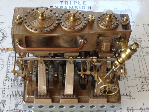
Big Triple Expansion Steam Engines

I knew that the triple expansion engine at Kempton Pumping Station would not be steaming today, but I wanted to see it anyway.

P1010794

It is sited next to the Thames, and pumped water from the river up to a holding reservoir.

As I walked to the building I could see the outlines of the huge engines through the windows.

But it was closed!  Damnation!

But, a kind volunteer, hearing how far I had travelled, let me in, and gave cart blanche to wander at will.

P1010716

There are two of these 63′ high monsters.  This one has been restored, and is run on steam occasionally, after the boilers have been lit for 48 hours.  The other engine is currently being restored.  The crankshaft of the second one was rotated with the barring engine about half a revolution, after no use since 1985.  Of course it is a triple expansion steam engine, and it now is run on a newish boiler which is gas fired.  Unfortunately the old Lancashire (?) boilers were scrapped.

The interior of the building is also interesting.  The walls are glazed bricks which look like tiles, and there is a 20 ton gantry crane.  The engines weigh 1000 tons each, so must have been assembled on site.

P1010736.JPG

The walls are glazed bricks.  Note the piston rings on the walkway.

Below the engines are huge water pipes, pumps and valves.

P1010734

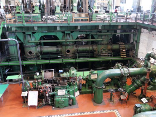
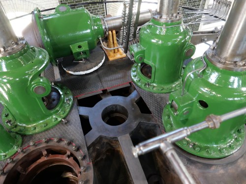
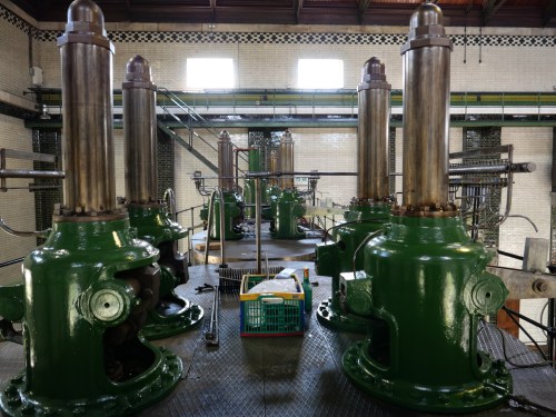
The space between the triples is occupied by two steam turbine driven pumps, about which more in a later post.  The space was originally intended to be occupied by another triple, which never occurred.   Interestingly, the triples are mirror images of each other, rather than identical, which means that a lot of components cannot be interchanged.  It probably made the plans more symmetrical and elegant.  Very British I suspect.

P1010740

Hey, that’s me.  In my tourist hiking gear

P1010743

Overall engine height 62 feet (18.9 meters)


P1010725.JPG

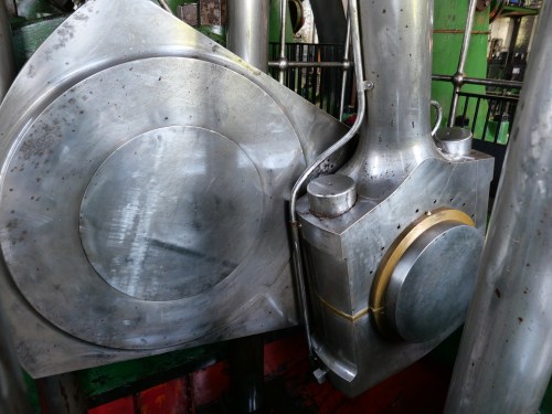
Monster big ends and cranks

P1010731

HP gauges.  Beautiful artwork hey Frank?!

P1010722.JPG

And aren’t those column bases works of art?

P1010726

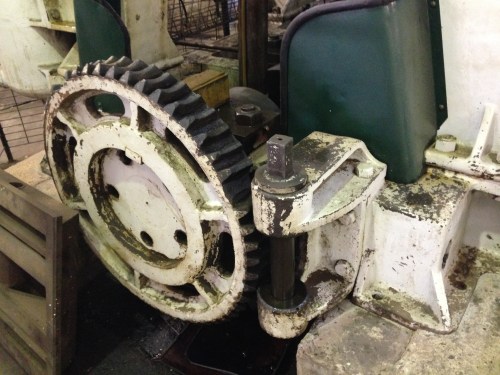
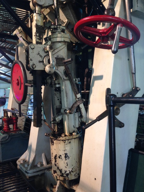
Barring engine.  Steam powered

P1010733.JPG

Those are my fingers against the flywheel, and teeth for the barring engine.

P1010751

One of many oil distibutors

P1010758

Right on top of the LP

P1010745.JPG

Piston rod and crosshead

P1010778.JPG

On top of the world

P1010776

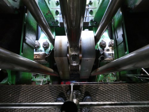
Looking down to a big end and the crankshaft

P1010771.JPG

Big machines need big nuts
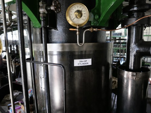
P1010747

The HP cylinder

P1010741.JPG

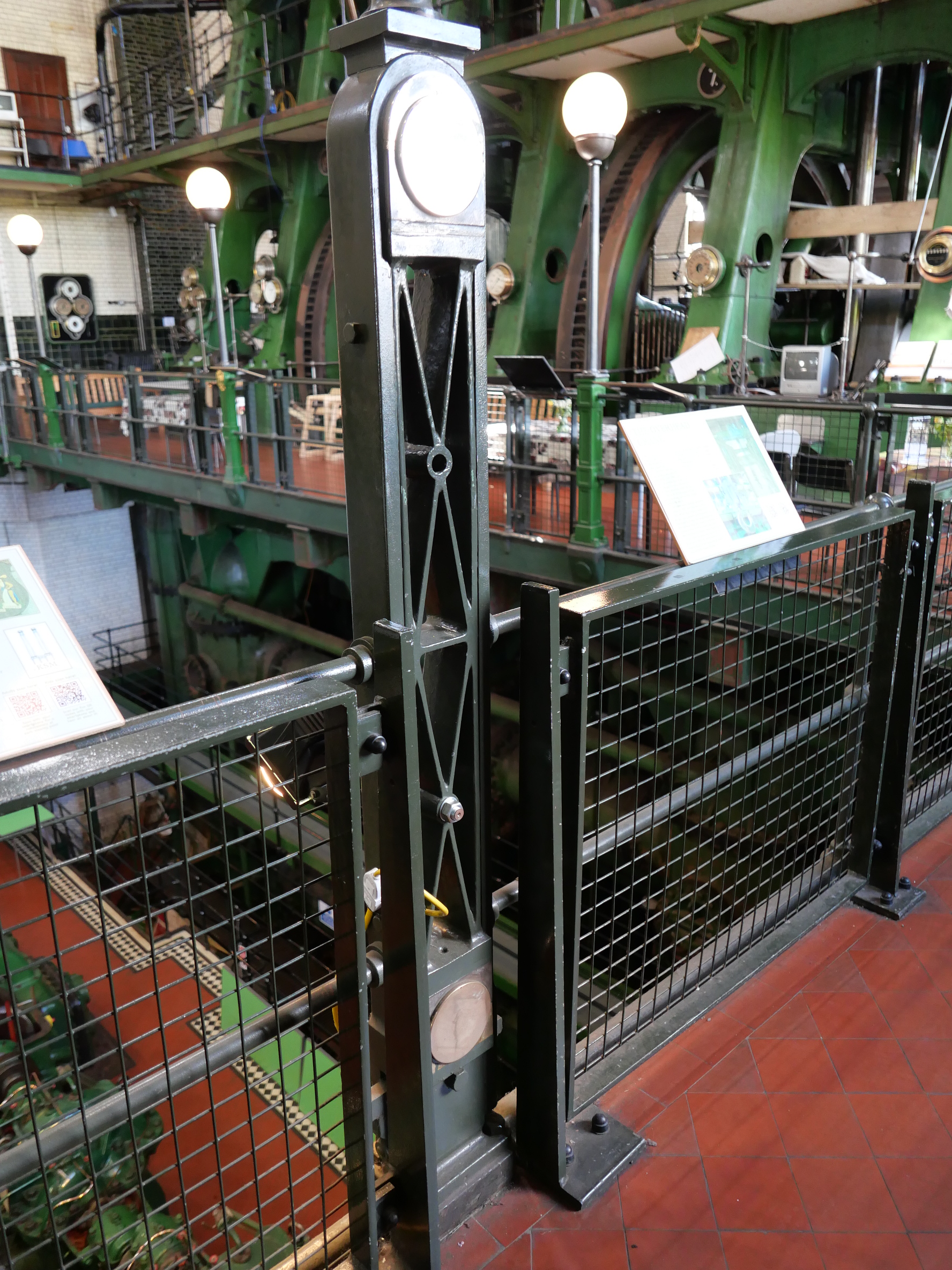
A volunteer pointed out that some of the safety fence posts are recycled Boulton and Watt parallel motion bars!

P1010728.JPG

check out those cylinder diameters and clearances!
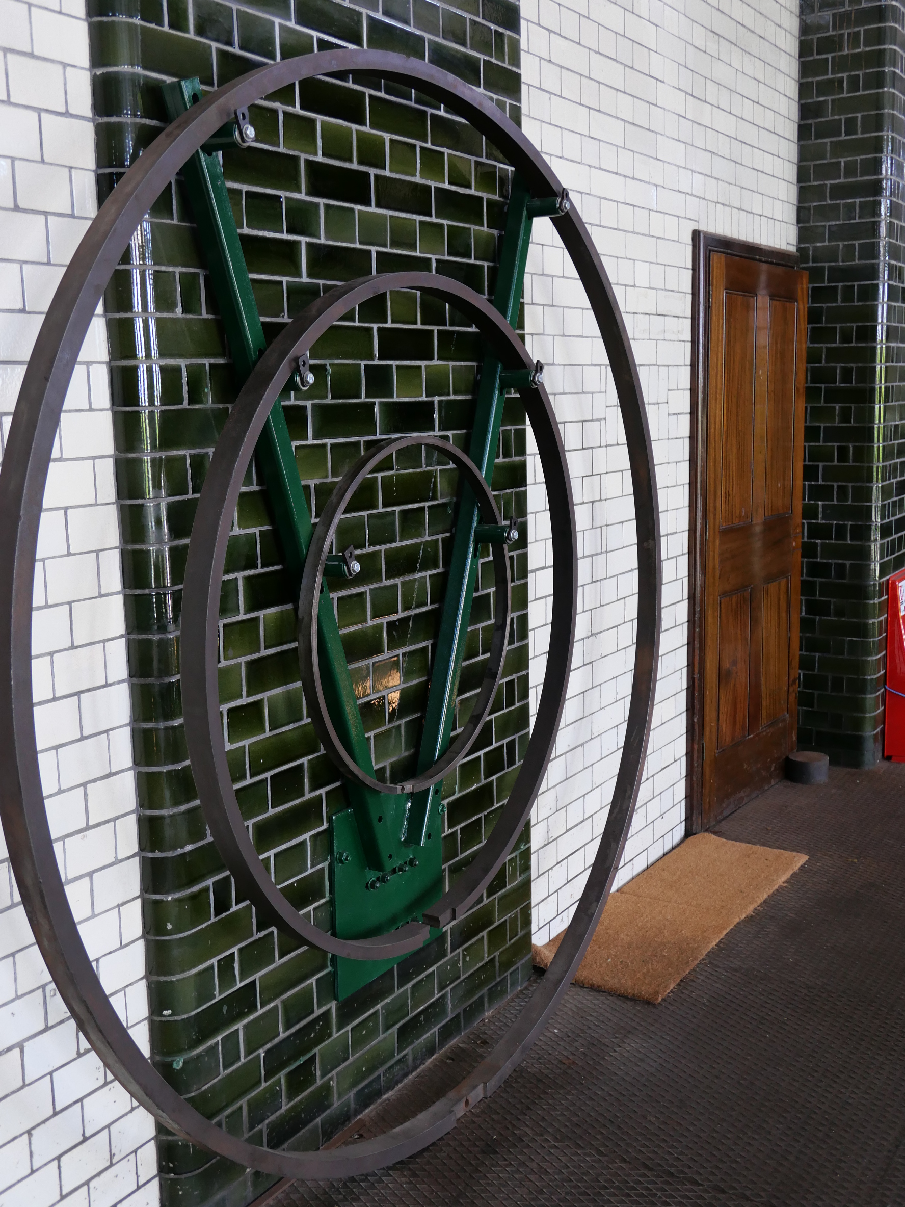
P1010763.JPG

Spare piston rings

P1010766.JPG

Piston ring, my finger
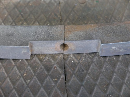
P1010764.JPG

Piston ring join.

I am rapidly running out of posting space, despite many more pics.  So I had better pause.  I didn’t get to the turbine engined pumps.  But I have many more photos…

Let me thank the very kind volunteers who spent time with me to talk about their engines at Kempton.  A marvellous experience.  I must return one day to see them under steam.

First taste of steam for the MODEL TRIPLE EXPANSION ENGINE

I made a video of this first run, but I am experiencing great frustration uploading it, due to our totally pathetic Internet speeds here in Australia.  I will include it later in this post, but the resolution is way down.  I will upload a higher res version next weekend.

1 setup.JPG

Stuart Tankard’s superb gas fired vertical boiler, was also getting its first run powering a steam engine.

2 setup.JPG

We did not connect the condenser until later.

OK, so here is the video.  Again, apologies for the low res quality.

Model Triple Expansion Steam Engine. First taste of steam tomorrow!

I was very excited to see my triple running reasonably well on air recently.  But it was tight, and required a decent gutful of air pressure to turn it over.  But it did go!

Then it seized.

The cause was the intermediate cylinder valve rod seizing in its guide.  Probably a bit tight,and not getting any oil.

So I have loosened the gland, installed a displacement oiler, and made and installed a flywheel.  I also finished the pipework around the condenser.

IMG_6173.JPG

Displacement oiler top left, brass flywheel, and pipework.  The condenser on a marine engine would have been cooled with seawater, pumped with a separate pump, but I have used the 2 pumps on either side of the Edwards air pump.  In future I might install another pump.  The book “Marine Steam Engines and Turbines” has been been very useful.  

IMG_6179.JPG

I just like all of the brass and copper and components in this picture.

IMG_6170.JPG

The flywheel is too big for the scale, but my model does not have the weight and momentum of a propeller shaft and propeller, so a sizeable flywheel seemed appropriate.  Later I will add some gear teeth on the flywheel and a cranking handle on a removeable pinion, which some medium size engines had to assist with cranking to a starting position.  

So, tomorrow I will hook my triple up to Stuart Tankard’s vertical boiler, and see what happens.  I am sure that steam leaks will be revealed.  Hopefully there will be a video worth posting!

Back to the Triple Expansion Steam Engine

IMG_6013

I installed these cylinder drains on the triple, but was not satisfied with their appearance because they looked too big.   So I bought some of a different pattern from Reeves UK.

IMG_6077.JPG

The new cylinder drains are smaller, and have a handle which is suitable for joining all 6 drains to one control handle.

IMG_6071.JPG

The new cylinder drains are a more realistic scale.  I suppose that I should have made them myself.  

IMG_6080.JPG

From above.  Getting them to line up was a fiddle.


IMG_6079.JPG

The crankshaft protractor now has a (temporary) pointer.  When the timing is finally adjusted, the protractor and pointer will be removed.  I am planning to make and install a crank positioning gear and pinion and lever.

IMG_5680.JPG

The crank positioning gear and pinion shaft on the full size, ship’s triple expansion steam engine at The Geelong Showgrounds.  It is on the low pressure end of the engine.  I will make something like this to act as a flywheel on my model triple.

Running in the Triple Expansion Engine

The Bolton 9 engine is assembled, almost completely.  The valves are approximately correctly timed.  I can turn it over by hand, just.  There are a few tight spots.

So today I mounted the entire engine in a lathe, oiled all bearings and slides, and tentatively ran it for a few minutes.   The lathe was set at 60rpm, in back gear.

All seemed OK, so I ran it for about 30 minutes.   Then increased the rpm to 90 for another 30 minutes.  After that the tight spots still exist, but much less pronounced.

IMG_5932.JPG


I kept a check on bearing temperatures with a laser thermometer, and none were running more than a degree or two different from any others.

The test did show that a low pressure cylinder drag link is touching the condenser, and will need some relief.  Also the high pressure cylinder eccentrics need to be repositioned a little on the crankshaft.  But nothing major.  And it was very nice to see everything moving in quite an impressive manner.

I will upload a video when the upload speeds are reasonable.


2 Triple expansion steam engines.

Triple Expansion Engine Update

Well, almost another whole year has elapsed, and still the triple is not finished.  Come December, and that will be 3 years that this project has occupied my thoughts and workbench.  With a few other projects in between.

Last week I assembled the components, in preparation for the Geelong Show.  GSMEE is a bit light on for new models, and it was suggested that the triple might fill some shelf space, despite being unfinished.

So I bolted it together.  All 429 fasteners!  And stood back and admired it.  It really is quite impressive, complex, and interesting.  So I took some pics.

IMG_5657.JPG

This is the condenser side, and the Edwards pump

IMG_5659.JPG

The other side is a bit lessy fussy, showing the steam inlet valve, the Stephenson’s links, weigh shaft  and controls.

IMG_5662.JPG

And the top, showing some of those 429 fasteners,

IMG_5665.JPG

The high pressure valve chest cover.  I will fill those holes where bolts cannot go.

IMG_5664.JPG

And the low pressure end, and links for the pump.

IMG_5660.JPG

And a close up of the steam valve and weigh shaft.

Not quite ready to run it yet.

It needs side covers for the cylinder block, drain cocks for the cylinders, and general freeing up.  It is still very tight.

Not to mention painting.  I expect that I will paint this one.   No idea of colours yet.

Assembling the Triple

img_4705

I got this far in assembling the model triple expansion steam engine, then lost courage and put it aside (again).  You can see the high pressure steam chest labelled “top”, the steam valve and handle, the drag links and levers for the reversing mechanism for the high pressure cylinder, and the worm and gear and control wheel for the reversing mechanism.   The reversing levers will need pinning with taper pins when the correct positions are finalised.  The short rod in the middle of the pic is temporary.  I need to make those properly.  The drag links clash with the condenser cover.  That was predicted in Bertinat’s notes.  The cover will need some material removed.  Slowly progressing, but taking frequent breathers.

The high pressure mechanisms are the most exposed, and easiest to access, and they were very tricky, and not yet compeletely installed.  I dread to consider what the intermediate pressure ones will be like, buried in the middle of the engine.   Then there is the valve timing.  Help!

A Full Size Weighshaft

The crowds were down at this year’s Truck Show at the Geelong Showgrounds.  Maybe the  38c weather prediction had something to do with that.

But those hardy souls who did turn up were treated to a feast of steam engines working on steam, and other antique engines popping away, as well as the magnificent trucks, tactors, and military vehicles.  There was a superb display of radio controlled trucks and excavators, and unbelievable machinery created with Meccano.

My interest was mainly focussed, for some reason, on the full sized triple expansion steam engine, which is the prize display in the vintage machinery shed.  it once powered a tug boat, and later a dredge on Port Phillip Bay.   And the following photos and video, if it will upload, show the bits which were of particular interest.

triple-expansion-engine-1-37

The red control handle top right is the main steam control valve.  The one on the left is the reversing control handle.  Note the big steam piston centre bottom.  It is a steam powered reversing control piston.   This engine was made in 1951, so is just about the last gasp in triple expansion steam engine development.

triple-expansion-engine-2-8

and the rod at top is about 5″ diameter.  It is the weighshaft, which carries the reversing levers for each cylinder.  On my model it is 5mm diameter.

triple-expansion-engine-3-6

Another view of the weighshaft and the levers.   Massive.

triple-expansion-engine-4-5

And note the drag links in the adjustable block.   That would have been set at intitial installation, and probably never altered since then.

Video of the big triple expansion engine working.  Maybe not.

For those following my triple expansion steam model engine build, I have put it aside again.  It is at the final assembly stage now.

Meanwhile, I am making some extra tool holders for the CNC lathe, and another ER40 chuck for the CNC lathe.

The ER40 chuck which I am currently using has an M5 shaft which is held with a drawbar, so I cannot feed work through the lathe spindle.  Plus it sticks out of the headstock a bit excessively.  So I have drawn up plans for a new chuck which I will fit to the lathe spindle and use the CNC to make the ER40 taper and threads.  Pics will follow.

And I really need some extra tool holders for the CNC lathe.  I have 5, but have material to make another 10.   The material is high quality cast iron off a scrapped T&C grinder.  I bought the grinder table cheaply (($AUD20 from memory) and have been gradually canibalising it over the last couple of years.   I have cut up the remains into rectangular 30x80x40mm chunks and will make the tool holders in the next couple of days, SWMBO and weather permitting.  Unfortunately there was insufficient material to make a long section, machine it, then cut it up, so each tool holder will have to be made separately.

Anyone for a swim?

High summer.

Hot workshop, wearing only shorts and boots.

triple-expansion-engine-1-36

I think that I will stay in the workshop.

Today was my deadline to have the triple expansion steam engine assembled and working, ready to be hooked up to steam at the Geelong Truck show.

GSMEE (Geelong Society of Model and Experimental Engineers) has a display in the Vintage Machinery Shed at the show, with many small working steam engines and the odd IC engine running.  Plus the Vintage Engine group has many full size engines running….  always a really interesting place to visit.

Another full day in the workshop would have just about had the triple in the display.  Unfortunately, I lost a day having to get a dental root canal abcess reamed out.

Then the day before yesterday, I could not find the drag links for my triple.   I had made them in early December,  and I was sure that I had put them in the multi- compartmented box where I store all such bits.  Despite thoroughly searching the box, at least 20 times, they were not there.  Could I have put them down somewhere else in the workshop?  So I searched the workshop.  No luck.  So I tidied the workshop, putting tools away, sweeping up rubbish, all the while searching.  Still no luck.   So I cleaned and searched my car, my bedroom, the living room, every where that I could concievably have left them.  (OK, I did not actually clean the bedroom and living room, but I did search).   I grilled my wife.  Had she seen them?  No.

So I slept on the problem.  Next day was going to be hot, so at 7am I drove to the workshop (it is about 15km from home), and searched again.   Still no luck.

So I searched the multi compartmented box for the 21st time.  I knew that it was a waste of time, but I was seriously considering making a new lot of drag links and bearings, probably a 2 day task.

There were some tiny containers with tiny fasteners in the compartmented box.  The drag links could not be them because they are too big, aren’t they…..??

The first tiny container, contained, you guessed it, the drag links.!!  They were smaller than I remembered.

Relief!

Self disgust!

Age related loss of short term memory…..

I had to get that one off my chest.

The other thing that I wanted to mention, is a superb machining blog site.  Actually, 2 superb machining blog sites.

The first is by Joe Pieczynski, who is a Texan who makes his living from machining.  His techniques and teaching are really, very, excellent.  Aimed mainly at an audience who are beyond absolute beginners.  Do a Youtube search on “Joe Pieczynski”.  Look at his video on machining ultrathin materials.

The second, I have probably mentioned before.  An Australian  machinist, whose videos and machining techniques have to be seen to be believed.  Mainly with a clock making interest, but the techniques can be used by all of us.  For some reason I cannot cut and paste his Youtube connection, but you will find it by doing a search on “Clickspring”.  What is particularly exciting in Chris’s “Clicksping” is that he is soon to embark on remaking an Antikythera calculator.  Watch it!  You will be hooked.


The Steam Supply Valve

This valve is the one which opens the steam supply from the boiler to the engine.  Triple expansion sgeam engines require a minimum of 100 psi, and preferably 120-200psi.  But amteur built boilers are rarely certified above 100 psi.

But compressed air gets to 120 psi with no drama.  So guess what will power this engine until I get around to making a high pressure boiler.

So the on-off valve needs to be pretty solid, so it does not explode and send hot fragments of metal in all directions.

Here is the main supply valve as specified and built for my triple expansion steam engine.

triple-expansion-engine-2-7

The lines in the background are a ruled exercise book, just to give a sense of the scale.  There are 9 components of precision machined components in this picture.  And about 2-3,  8-12 hr very happy days in the workshop to make.  This is all made from bar stock.

triple-expansion-engine-3-5

And this is the handle which controls the on – off steam supply.  Pretty sexy hey?

It all attaches to the high pressure steam chest and cylinder.

triple-expansion-engine-1-35

Hey!  I like this shit stuff .  Even if most of the rest of humanity is yawning.


SS Valve Rods

Making the new valve rods, as predicted, took me an entire day.  They required a high degree of precision, and being in stainless steel, not an easy material to machine, and quite thin and delicate, multiple stages in the machining.

But before I started on the valve rods I made myself a new spanner for the collet chuck on the CNC lathe.  I had been using an adjusting spanner, which was continually  going out of adjustment and causing angst.  The tool merchants did not have anything suitable (46mm opening, and thin profile), so I made my own.

triple expansion engine - 1 (34).jpg

The 46mm spanner being cut from 6mm steel plate.

triple expansion engine - 9.jpg

It is a bit prettier after this photo and being painted.  The rounded jaws facilitate easy application to the collet chuck.

triple expansion engine - 8 (1).jpg

Tightening the ER40 collet chuck with the new spanner.  It works very well.

So then I got on with the new valve rods.  Some end of day photos follow.

triple expansion engine - 2 (6).jpg

The valve rod is the silver coloured rod.  Actually stainless steel.  This photo shows the high pressure cylinder valve and valve chest.  There are 2 other valves, one for each cylinder.  All different sizes.

triple expansion engine - 4 (4).jpg

The high pressure valve chest and valve, the valve rod and guide.  On the right is the Stevenson’s link, yokes and eccentrics which control forward and reverse.  This setup is repeated for each of the 3 cylinders.  This is hooked upto the worm and gear which was shown a blog or two ago.  There are 22 components for each, not counting fasteners.

triple expansion engine - 7 (1).jpg

The low pressure setup.

And thank you to those readers who responded to my whinge about likes and comments.  I will continue this blog until the triple expansion steam engine is finished, and hopefully running.  Not sure after that.

Triple Underbelly

“Underbelly” has a particular resonance for readers who know what the Yarra is and that Collingwood is a place and not a British admiral.

In the instance of my triple expansion steam engine, it refers to the bits and pieces underneath the cylinder block.  The glands which prevent steam leaks from the con rods and steam valve rods, the and valve rod guides.  These unsung heroes of the steam engine have taken 2 entire days to make.   And here they are….

triple expansion engine - 1 (32).jpg

This is the cylinder block, upside down.   You can see the valve rods. the valve rod guides, the valve rod glands, the piston rods, the cross heads (unfinished), the piston rod glands,  and the cylinder bases.   Give yourself 2 marks for each correctly identified item.  The 6 hex plugs on the side are temporary, until I get around to making some cylinder drain valves.

I started to count the number of holes drilled and tapped in this view, but gave up at 100 and still not half way.  This engine better bloody work!

triple expansion engine - 2 (4).jpg

Note the letter stamped into the cylinder base.  Many parts are similarly stamped.   The studs in the intermediate piston gland are temporary.

triple expansion engine - 4 (3).jpg

Just a different view.

I have decided to replace the valve rods which are made of brass, with stainless steel ones. That will take an extra day, which might exceed my second, self imposed, deadline.  But if it does, well too bad.

By the way….   I am considering whether or not to continue this blog.   It does take time, and is not free.  If you read this and are not totally bored, the odd “like” would not go un-noticed.  A comment would be even better.

Reversing Gears and Handwheel

Another 2 days in the workshop.  Heaven.

I had made a worm drive and gear using an M14 x 2 tap, but it did not look the part, despite being functional.   The problem was that the threads were sharp triangular and they did not look correct.

So I made a worm drive and gear using Acme specifications.  The teeth have a chunkier squarish look.  More authentic.

I ground a lathe cutter and used it to make the worm drive in gunmetal, and another identical thread in 14mm silver steel (drill rod).   The steel thread had cutting edges formed, and when finished it was hardened by heating red hot and quenching.  After hardening, a file would not mark it.  I did not bother to anneal it, since it would be used only to cut cut brass or gunmetal.  The hardened tool was used to make a gear in gunmetal.  Unfortunately I did not take pictures of those steps.

triple-expansion-engine-1-29

Showing the handwheel, worm drive and gear.  the shaft is mounted in gunmetal bearings which are bolted to the columns with BA8 bolts.    The thread is Acme. 2mm pitch.  The handwheel will control forward-reverse of the triple expansion steam engine.

triple expansion engine - 1 (25).jpg

In order to determine the position of the bearing bolt holes for the worm drive, I used SuperGlue to tempararily join the worm and gear.  

triple expansion engine - 1 (27).jpg

When the position of the bearings was determined, the holes were drilled 1.8mm and tapped.  the taps were BA8, about 2mm diameter.  The engine is held vertically on the milling table, being cramped to a large angle plate.  The holes were drilled accurately on the mill.  The threads were made using a tapping head made by me from plans published in “Model Engineer” by Mogens Kilde.   The double parallelogram of the tapping tool keeps the tap vertical.  The tap did not break.

triple-expansion-engine-1-28

Close up photo of tapping the BA8 threads.  Showing the bearing, shaft, worm drive and gear.  Note the Acme thread.  The bearing is Super Glued into position to facilitate the drilling and tapping procedure.  The Super Glue will be removed later.

triple expansion engine - 1 (31).jpg

The final step for today was to make the handwheel.  It is 1.5″ diameter.  The rim is 1/8″ brass and the spokes are 1/16″ brass.  I made 4 of these, with each being better than the last.  I softened the 1/8th brass before winding it around a 32mm pipe to form the rim.  The join in the rim was silver soldered.  Then the rim and the hub were drilled using a tilting indexing head on the mill.  I soft soldered the spokes on intital handwheels, but the final (and best) examples were glued with Loctite.  Loctite allows a few minutes for adjustment of the spoke lengths, whereas there is only one go with the soldering.

It is looking interesting, Yes?  And there are 3 spare handwheels.  The rest of the reversing mechanism components were made several months ago.  Almost ready to install them.

Broken Tap Removal

In a previous post I admitted to breaking a BA7 tap in the Edwards air pump of the Triple Expansion Engine, and being unable to remove it.

The hole being threaded was one of 4 to be used to hold a water pump to the air pump. It was 2.5mm diameter (i.e. pretty tiny)

I tried to grasp with pliers the fragment still protruding but it then broke below the surface.

I tried to break up the embedded tap, using a HSS punch, with partial but inadequate success.

I briefly considered drilling a hole from the other end, and punching in the reverse direction, but that would really have compromised the pump.

So I decided that the three remaining bolts would have to be enough.

A night sleeping on the problem.

Next day, with a fresh determination, I decided to attack the problem again.

I had some used carbide milling cutters 2mm diameter, and I was prepared to sacrifice one or two of them.   So I carefully set up the Edwards pump in the milling machine.

triple-expansion-engine-1-23

You can see the three good tapped holes.  The carbide milling cutter chomped away at the broken tap, and using gentle pressure, and ignoring the metallic screeches, the tap was broken up and most of the fragments came out.  I was prepared to sacrifice the milling bit, but it seems to have survived this insult.  The harder metal always wins.   It was probably fortunate that the tap was carbon steel and not HSS.

Somewhat surprisingly, the tapped hole was in reasonable condition, and it accepted a BA7 bolt, although I will not be aggressively tightening this one.

Triple Expansion Steam Engine -The water pump

john and audrey - 5.jpg

The triple will not be finished by Xmas.  No chance of getting into the workshop while we are looking after 2 grandchildren.  So the new aiming completion date is Jan 6, in time to run the triple on steam at the Geelong truck show.   If I don’t meet that deadline, the next access to steam will be the end of 2017.  I really do not want to wait that long.

So the next component to produce out of a chunk of gunmetal is the water pump.

triple-expansion-engine-1-18

There are two cylinders in the water pump.  The gunmetal castings appear to be good quality.

Most of the machining will be done on the mill.  But I need a datum surface, and have decided that the attachment plate is the most appropriate.

triple expansion engine - 1 (20).jpg

I do not need the small cylindrical protruberance, but that chunk of gunmetal might be handy for something else (eg as a bushing), so I parted it off and saved it.  Lovely parting tool is from Eccentric Engineering.

triple-expansion-engine-1-17

Then turned a flat surface.  On the mill I machined it to a rectangle.   Diamond tool is also from Eccentric Engineering.

triple expansion engine - 1 (21).jpg

The two water pump cylinders are bolted to the air pump.  BA7.  A broken tap is entombed in the air pump forever.

triple-expansion-engine-1-22

When I get back into the workshop I will machine the rest of the pump parts.

MAKING SMALL SPLIT BEARINGS FOR THE TRIPLE EXPANSION STEAM ENGINE

triple-expansion-engine-1-15

The bearings in the drag link are not split, because they can be slid onto the shaft.  But if there are obstructions to sliding, (such as big ends on a crankshaft), the bearings must be split, and assembled when in position on the shaft.  The bore in the intact bearings in the photo is 4mm.  The split bearings have a 5mm bore.  They are all bronze, but the split bearings have been heated then dipped in sulphuric acid so the colour has changed.

triple-expansion-engine-1-7

The first step in making split bearings is to machine 2 strips of metal, of identical dimensions.

triple expansion engine - 1 (8).jpg

Next the strips are soldered together.

triple-expansion-engine-1-9

The bearing holes are drilled and reamed exactly to finished size.

triple-expansion-engine-1-10

The strip of soldered metals is attached to a sacrificial base plate and the outside of the bearings are machined to final size and shape.

triple expansion engine - 1 (11).jpg

Holes are drilled to take the bolts which will eventually hold the halves of the bearings together.  (1.6mm holes in this case).  The bearings are then heated to melt the solder and separate the halves of the bearings.  Sulphuric acid was used to remove the carbonised crap left on the surface of the bronze by the heating torch.

triple-expansion-engine-1-15

The bosses around the holes was an extra machining step.

Drag Links for Reversing Mechanism on Triple Expansion Steam Engine

A bit more progress today.

I spent the whole day making these drag links, and I was pretty happy with the result.

Then I realised that I need 6, and I had made only 3.  (well there are 3 cylinders you see).

So you know what I will be doing tomorrow….

triple expansion engine - 1 (4).jpg

The drag links are the 3 items with the bearings at the ends, and the connecting rods.  Those rods are 1.6mm diameter (1/16″ inch), and the nuts are BA 10

triple expansion engine - 2 (3).jpg

I dropped 2 of the nuts.  Gone forever.

The final 20% takes 80% of the time

IMG_4623.JPG

The weighshaft, supported on its brackets.  It will be pinned with taper pins to the shaft.  Also finished the reversing lever and reversing arm.  The reversing arm has gunmetal bushes.  About 2 x 8 hour days in the workshop to make these bits.  Just as well it is a fun hobby.

Triple Expansion Steam Engine resumes

Busy at this time of the year.

Making some wooden toys for the grandchildren for Xmas.

IMG_4589.JPG

Not sure whether these are ducks or chooks.  My talented wife brings them to life with colours.  When pushed by 1-2 year olds they waddle with an entertaining flap flap walk.  

Preparing the surgery building for sale.  Removing and storing 34+ years of medical records, moving furniture, arranging repairs and painting etc etc.  Feels strange to be no longer a registered medical practitioner, but I know that it was the correct decision to retire.  It has taken 2 years to totally burn the bridges by dropping my medical registration, and selling the surgery etc.

Model Engineering Club annual exhibition.


IMG_4580.JPG

This model quartz crusher at the exhibition was driven by a hit and miss engine.

IMG_4574.JPG

Another superb engine at our exhibition.

Plus ongoing military history book reading and reviews.

Slashing long grass, to reduce the summer fire risk.

Assembling and installing a kitchen into a rental property.

So it was a treat to get some time in the workshop today.  I had previously made the layshaft brackets for the triple expansion steam engine, so I spent a happy few hours setting up an angle jig on the milling machine to drill and tap holes to attach the brackets.

IMG_4583.JPG

This is the setup.  An adjustable angle plate was bolted to the milling table, and the angle was set so the columns were horizontal.  The layshaft brackets were Super glued to the columns with the shaft in place after filing to get the brackets quite level.  The holes were spotted through, then drilled (1.6mm) and tapped (2mm).

IMG_4586.JPG

The layshaft bolted in position with M2 nuts and studs.  M2 is very similar to BA7, and a lot less expensive, and is stainless steel.  Way to go!


Other People’s Triples

Click on the link to see a model triple expansion steam engine running on steam.

MAIN BEARINGS FOR TRIPLE

Each main bearing consists of 2 gunmetal halves which fit into a slot in the base, and a cap which bolts to the base.  There are 6 of these.

I machined the gunmetal castings, and made the caps.

Before I finished the machining or drilled the holes for the bolts, my phase changer failed, so I finished the job on my (single phase) drill press. Not ideal but adequate.

The Phase Changer has failed at least once every year since I bought it 5-6 years ago.  It is the least reliable machine in my workshop.  Repairs to it seem to take at least 3-4 weeks on each occasion, which is frustrating.  I will borrow a 3 phase diesel generator to keep the workshop in action while waiting (again) for the repairs.

One of the 6 main bearings and caps.  The hole has been roughed out, ready for accurate boring

One of the 6 main bearings and caps. The hole has been roughed out, ready for accurate boring

The 6 main bearings sitting in their slots.  The hold down bolts are ready to be installed.  The bearing surfaces will be bored when I have some 3 phase power again.

The 6 main bearings sitting in their slots. The hold down bolts are ready to be installed. The bearing surfaces will be bored when I have some 3 phase power again.

STEAM CHEST PROGRESS

Apart from contending with fauna in my workshop (a tiger snake) , I did actually make some progress today.

IMG_2602

All three steam chests are now attached to the cylinder block. This photo shows the high pressure cylinder steam chest. All of the screw holes are threaded and ready for the screws. More BA7 screws on order.

TRIPLE BORING CYLINDERS

Today I bored the cylinders on the triple expansion engine.

Most model engineers would perform this task on a lathe, bolting the work to a faceplate or possibly using a large 4 independent jaw chuck.

The most accurate machine in my workshop is my CNC mill, so I decided to use the mill.

The setup is as depicted in the photo below.

IMG_2562

The cylinder boring setup.

IMG_2565

Cylinder boring complete. The setup took a couple of hours. The boring process also took 1-2 hours.

Of course, the high pressure cylinder needed to be center drilled, then drilled to 6, then 12, then 15mm, then bored to size 22.23mm.
Doing the job on the mill, I can be confident that the bores are all on the center line, all parallel, and the centers all correctly located. The intermediate cylinder finish was not acceptable, due to some chatter on the final cut, so I bored it out an extra millimeter to rectify the problem. The extra size will not matter. The piston (and rings?) will be made to fit the bore.

At the end of the session, I have left the setup intact, so I can check whether further processes can be performed using the same setup.

CASTINGS ARRIVE AT LAST!!

Today I received a 16.6kg package by courier. It was too heavy for the regular post.  It contained the castings for the model triple expansion steam engine, which I am hoping to build in the next year or so.  I am told that on average this model takes 3000 hours to complete.  That is a scary thought.  Almost unbelievable.  But when I calculate how many hours went into the much simpler single cylinder beam engine (maybe 600-800), I guess that it is not an unrealistic estimate.  Just as well that I am close to retirement age.

The castings were made in NSW Australia, and supplied by Kelly Mayberry at EJ Winter.

All carefully wrapped

All carefully wrapped

The castings are all brass, gunmetal, or bronze

The castings are all brass or gunmetal.  There must be at least 100 of them.

Looks like the condensor chamber, as part of the engine frame.

Looks like the condensor chamber, as part of the engine frame.

The base.

The base.

A large chunk of brass

A large chunk of brass, the intermediate and low pressure cylinders.

The castings appear to be free of holes or defects

The castings appear to be free of holes or defects