
How to time a Model Triple Expansion Steam Engine
by John
The daunting aspect of timing the triple delayed the completion of mine by at least 6 months. In the event, it was not difficult.
If timing a steam engine is not a particular concern of yours, I suggest that you turn off now. Otherwise this will be particularly boring. This post is in response to a request by a reader.
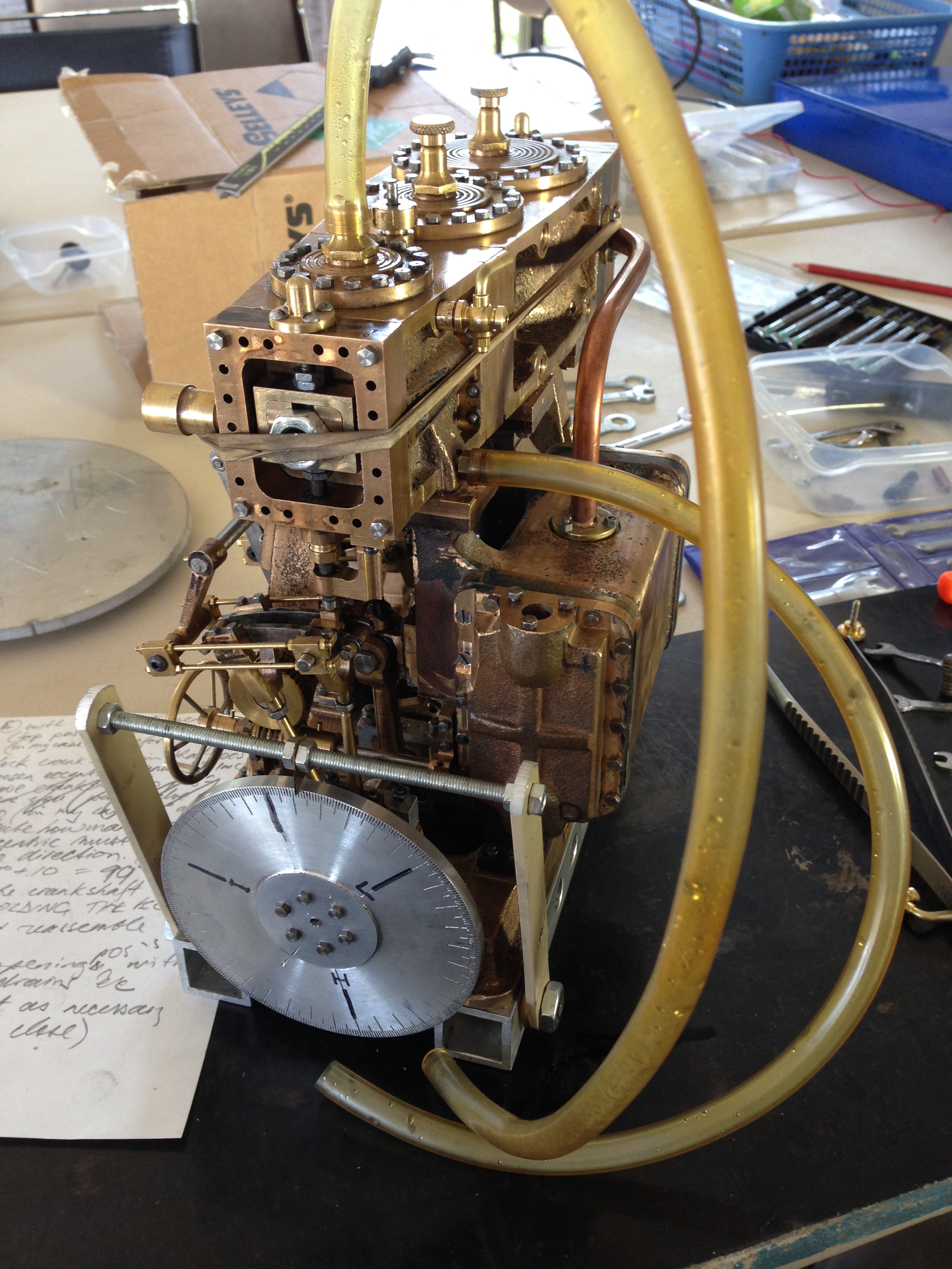
The engine needs to be pretty much completed and assembled. Everything fitting. Crankshaft rotating. Valve rods tightened. Stephenson’s reversing mechanism assembled and working. Cylinder drains installed.
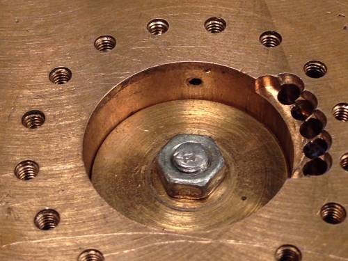
Next I suggest that you make or buy a 360 degree protractor, and attach it to the crankshaft at the high pressure end. Like this.
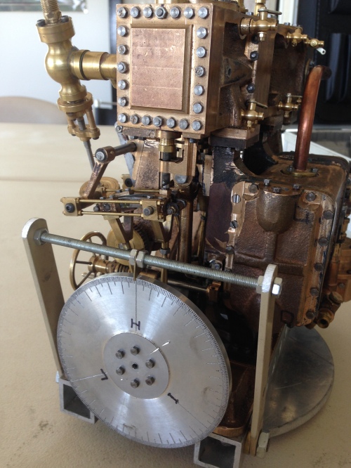
Note that top dead centre (TDC) of each piston is marked (H,I,L), there is a pointer, big marks at 120 degree intervals, and identifiable marks at 10 and 5 degree intervals. I added a rotation arrow later, because it is easy to mistake clockwise and anticlockwise directions when making adjustments.
Next, decide where in the cycle you want steam to be admitted. On expert advice from a marine engineer who is also a model engineer, I decided to admit steam at 10 degrees after TDC. (thanks Rudi!). I also decided to cut off admission of steam at about 70% of the power stroke. (pretty standard).
The easiest valve to time is the low pressure valve. It is on the end of the engine. It is the biggest, and there is not much engine stuff getting physically in the way. Despite that, I decided to start with the high pressure valve. It also is on the outside end of the engine. The reason is that I wanted to follow the passage of the steam flow, in order to understand what was happening. Each cylinder is timed separately, independently. So the order is, high pressure, intermediate pressure, low pressure. Forward direction first, then reverse, for high, then F & R for IP, then F&R for LP.
The timing is adjusted by 1. changing the distance between the crankshaft and the valve, usually by adjusting the length of the valve rod and 2. by changing the position of the eccentric on the crankshaft.
Firstly, the valve must move equally over the steam inlet slots. (the top and bottom ports). The point at which the inlet slot starts to open is noted on the protractor for both steam inlet ports. The number of degrees before or after TDC is noted for the top port, and the procedure is repeated for the bottom port. For the bottom port Bottom Dead Centre (BDC) is the reference point on the protractor. The angle should be identical for TDC and BDC. If it not identical the length of the valve rod needs to be adjusted. On my machine, that was done by adjusting the nuts holding the valve rod to the valve bracket, but it could be the valve rod to the eccentric strap.
Determining the point at which the steam inlet port starts to open is easy. Remove the valve chest cover, bolt the valve chest to the cylinder block, and rotate the crankshaft by hand until the port is obviously visually open. Cut a sliver of paper 5-10mm wide, (I used copy paper), measure the thickness of the paper (0.1mm in my case), insert the paper into the open port, rotate the crankshaft to close the port until the paper is jammed, then while applying tension to the paper, slowly rotate the crankshaft to open the port, until the paper just starts to move. At that point the port will be open by the thickness of the paper.
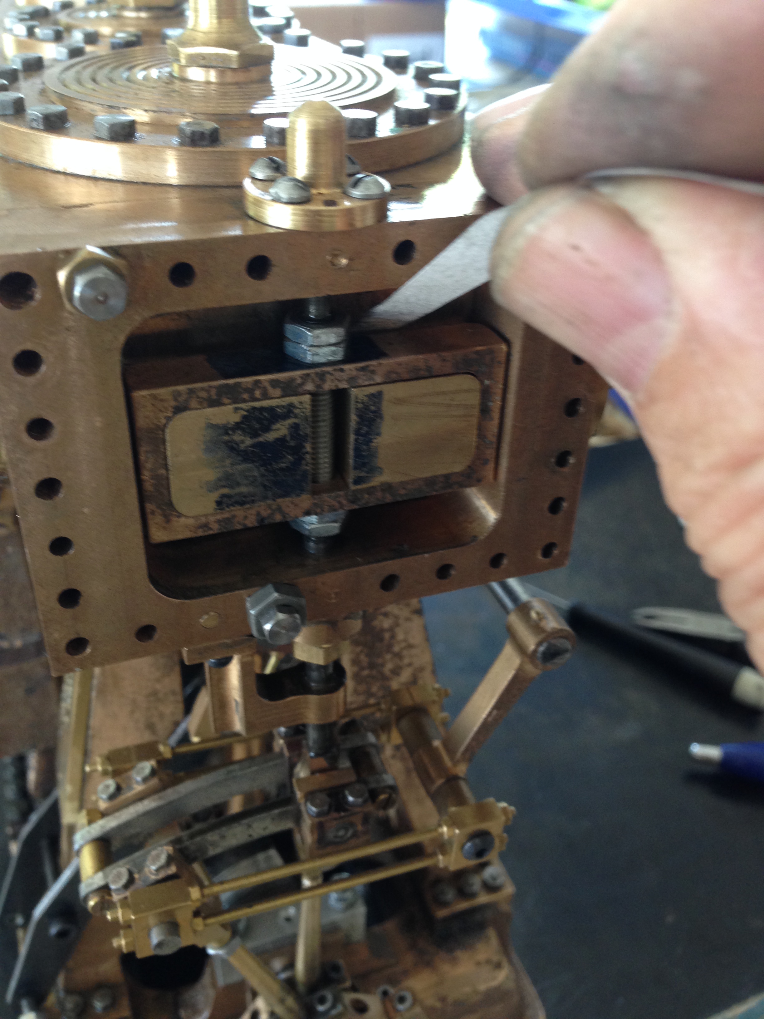
The valve cover is off, a sliver of paper is pushed a centimeter or so into the port, the crankshaft is rotated to jam the paper then the crankshaft is rotated in the direction that is being adjusted until the paper is just released. At that point the port is open by the thickness of the paper. I calculated that 0.1mm was equivalent approximately to 3 degrees of crankshaft rotation. So whatever was displayed on the protractor, I subtracted 3 degrees to get to the exact point of port opening.
when the valve moves exactly equally up and down over the steam entry ports, the point of opening is noted on the protractor relative to TDC of BDC, depending on which is being measured.
The eccentric grubscrew needs to be loosened, and rotated on the crankshaft to bring the point of port opening to 10 degrees past TDC. Then the grubscew is tightened. BDC will automatically be correct if the centering process has been done accurately.
I had bored a hole in the eccentric strap to allow access to the grubscrew from underneath the engine. That meant that the crankshaft had to be in a certain position to allow access to the grubscrew, not necessarily TDC or BDC or whatever. That does not matter. What matters is that the eccentric is rotated a certain number of degrees on the crankshaft. I did this by using the Allen key to loosen the grubscrew, then using the Allen key to hold the eccentric fast, while rotating the crankshaft. Then tighten the grubscrew, being careful to not move the eccentric. The measurements need to be rechecked of course. With practice, it is not difficult, and can be accomplished first go in most cases.
If this all sounds complicated and difficult, it really is not. But I did need to make a record of every step and measurement and direction.
For the intermediate cylinder, the HP cylinder block needs to be removed. The HP valve chest can be retained, just swung out of the way, retaining the previous settings.. You have to be careful, but this method does save a heap of bother.
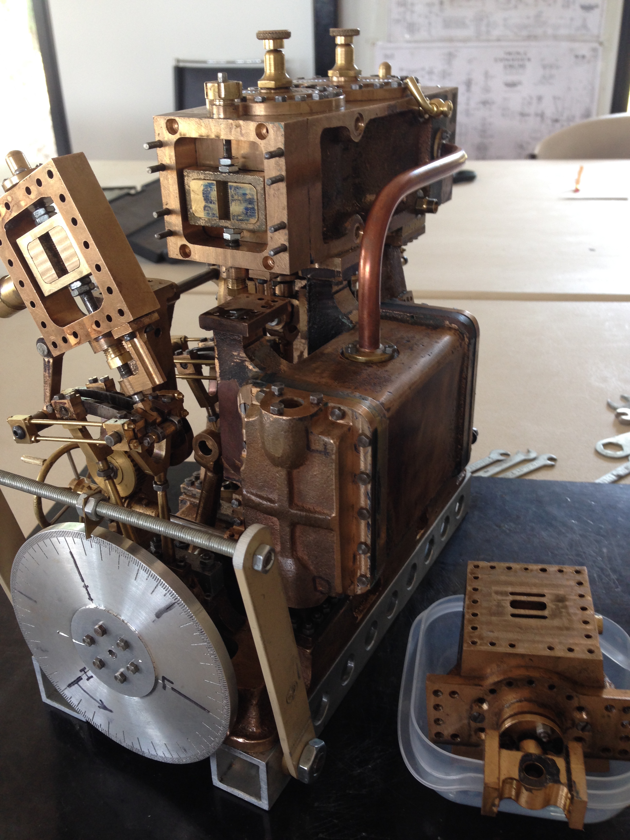
One thing I would suggest. When the opening points of both IP inlet ports are determined and set, I suggest that before the HP cylinder block is reassembled, that the IP valve rod is measured above the IP valve chest. And that the measurements are recorded and placed in a secure vault. Those measurements can be used for any future adjustments of the IP valve, without the time consuming and very fiddly necessity of removing the HP cylinder block.
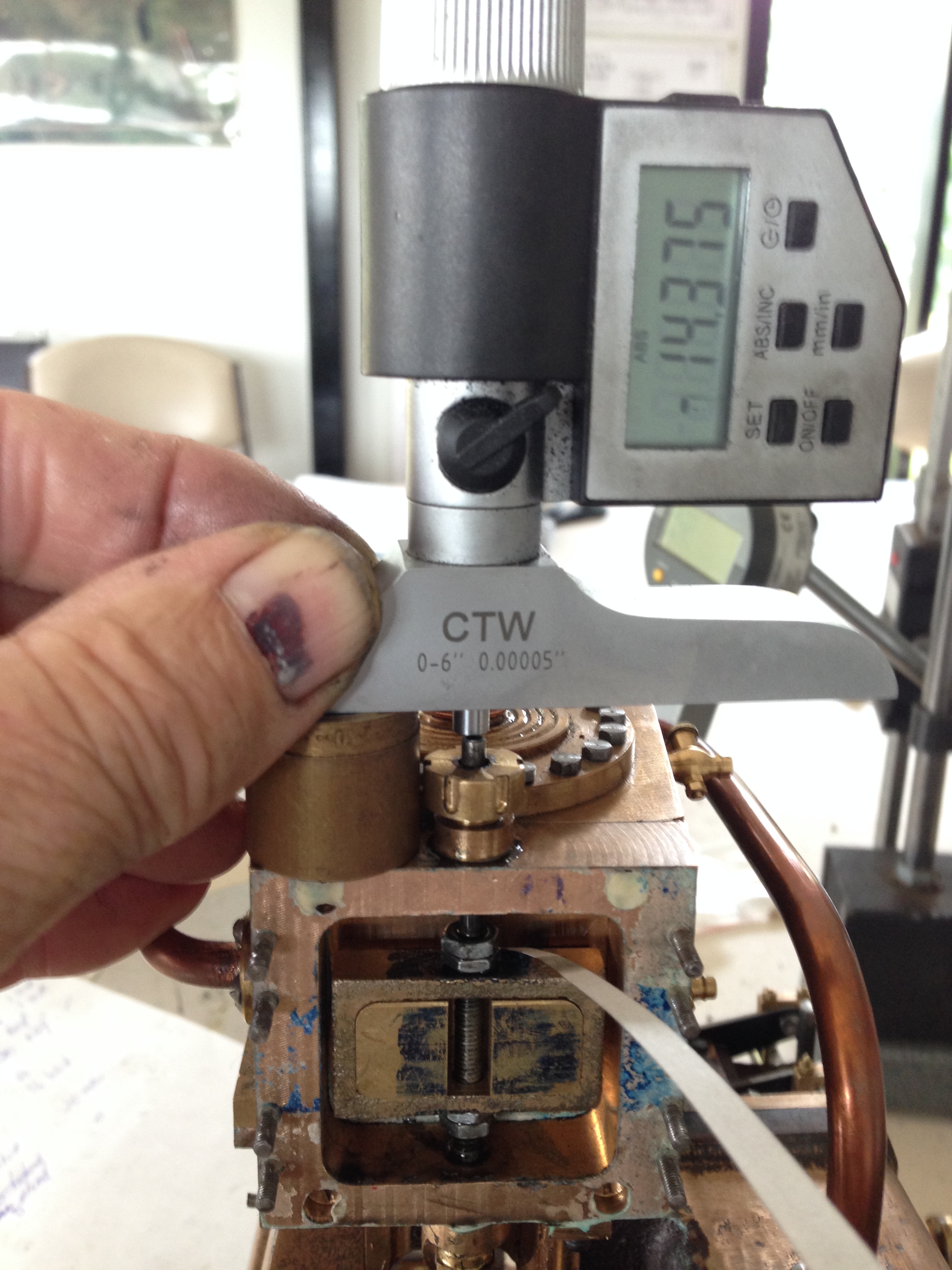
I have determined the opening points for the intermediate cylinder using the paper method. With the depth micometer on the valve rod above the valve chest, I am measuring and recording those positions, for possible future use.
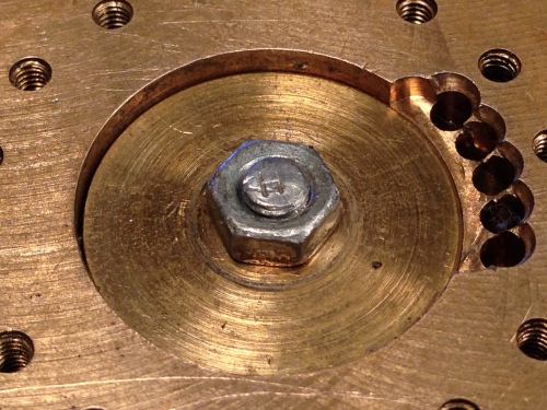
And I have a confession. The next photo shows the HP upper cylinder drain, and the same view at top dead centre. As you can see, at TDC the piston blocks the drain.)!*!) Read on.
There is another method for determining the opening point of the valves.
Plastic tubes are pushed on suitable points for the cylinder to be set, in this case the HP. The valve is pushed against the valve face, in this case with rubber bands. One blows into the appropriate tube while rotating the crankshaft. When the port starts to open, you can hear your exhaled breath coming through (if your hearing is OK, which mine is not). The protractor reading is recorded, and used as before. Note: the drain cock passages MUST NOT be occluded by the piston at TDC or BDC. In my case, this proved to be a problem, hence the use of the strip of paper method.
So, I hope that this is of some use. If my description is jaberwocky, please send a message and I will try to help. John.

That was very interesting
LikeLike
Russell, you have either tried to time one of these, or you are as eccentric as me. Cheers. John
LikeLike
John,
have you ever thought about how the timing of one cylinder affects the timing of the next cylinder ? starting with your values +10 … +101.5
HP exhaust 190 … 281.5
IP intake 250 … 341.5
this gives “effective” timings, IE the 31.5 degrees where they overlap, of
HP exhaust 250 … 281.5 (bdc+70 … bdc+101.5)
IP intake 250 … 281.5 (tdc+10 … tdc + 41.5)
the “effective” intake closing is early, which is generally OK, that means larger expansion vs intake ratio and better efficiency, but the “effective” exhaust opening is late, which means re-compression which means lower efficiency.
so the question is are the triple expansion “effective” valve timings good, or even just acceptable, being based on a typical single cylinder timing, or should they be adjusted to compensate for the triple expansion effects ?
Peter A Lawrence
(PS, a 2 cylinder compound engine with the cylinders phased 180-degrees apart would not have any such problems (with Stephenson gear), but everyone builds them with 90-degree phase, which does.)
LikeLike
Peter, I took advice from 2 members of my SMEE club, one of whom was a marine engineer onships with triple expansion engines and who is now a model engineer, and the other who currently works as a marine maintenance engineer and also runs the triple expansion engine at our vintage machinery association. Their advice was that each cylinder is timed as a separate unit so that is what I did. And it runs!
I take your point that the exhaust timing from the preceding cylinder should have an effect on the intake of the next cylinder, but in a model of this size, which actually runs, I am not intending to fiddle further. Maybe later on……
Thanks for the input John.
LikeLike
But still thinking about your comment and I will discuss your point with my expert advisors. John
LikeLike
Hi John, if I could be so forward as to ask if you could email me please in regard to the Stuart Triple.
Thanks and Regards,
Steve
LikeLike
Hi Steve, I am not sure what you are asking. I have no direct experience with the Stuart triple. In general Stuart castings and plans are excellent, but when I look at photos of the Stuart triple and the Bolton 9 triple I am happy that I went with the Bolton 9.
John
LikeLike
I have been trying to find someone in Australia that can set the timing up on a completd Stuart Triple. I saved from a scrap metal merchant and gave it some air when I got home but couldn’t get it to turn over. I asked a few members of my last cal engineering club but no success as their expertise lies with loco’s. So took it back home to have another crack at it but I broke my back before I could do anything. I was given your blog site by a friend in the UK. Do you know f anyone in Australia that may be able to help ?
LikeLike
Steve,
you might be able to time the Stuart triple by using the info in my blogs from late 2017. But your best bet would be to obtain a set of building instructions for the triple from Stuart in UK. That will almost certainly contain the timing info. John
LikeLike
Steve, I just read your messages on Stuart triple engine, I just bought one from UK ebay, now waiting for it to arrive here in AUs.
A friend now passed built one and I did help to get it running and then with reversing gear, so it will be interesting to finally get one myself.
Would be interested in the timing info.
EM wbjofesine@gmail.com
LikeLike
William, it seems quite a long time since I wrote about timing the triple. In fact, I tend to refer to my old posts to remind myself how I did the timing. If you have specific questions about the posts I will try to answer them, but I doubt that I will be much use to you, particularly considering that the Stuart is not identical to the Bolton. John
LikeLike
Pulled the cover off the tug boat today to double check…there are no Stuart emblems in the castings which makes me think I have been given a bum steer – there are no marks on any castings. Any guide as to whom I could send a couple of pics to try and ID it ?
LikeLike
Hi Again, further to your suggestion, I just received a copy of the correct timing sequence by email. I’ll give that a crack. If anyone needs copy, just email me and and send it on. Steve
LikeLike
Steve, that would be of interest to some other readers. If you send it to me I will post it on the blog, with acknowledgements to yourself. John jviggers@iinet.net.au
LikeLike
Hi John, did you get the email I sent with the timing instructions for the Stuart Triple ?
LikeLike
Hi Steve, yes received, but unfortunately I was unable to read it because the attachment would not enlarge. John
LikeLike
Iâve enlarged it as far as I can with âWORDâ â if this is of no use, flick me back an email…Iâll retype it ….in a readable size for both of us !! ð Or some other black magic
SS
Sent from Mail for Windows 10
LikeLike
Good morning John, as an ex apprentice fitter machinist and toolmaker in the early 1950’s I’m fascinated by the pictorial descriptions of your construction and machining operations. I discovered your site while researching the Victorian era smooth bore guns sent to the Australian Colonies for protection against perceived threats of foreign invasions by America, France and Russia. I look forward to your future posts. Regards Don Chisholm-Smith, Tasmania.
LikeLike
Excellent! Someone else interested in gun history. I look forward to further communications Don. The technology, history, and modelling have led me down paths which I never anticipated, but which have been engrossing.
LikeLike
Good evening John, thankyou for your reply. I discovered your site while looking for photographs of Palliser converted smooth bore muzzle Loading guns and Royal Carriage Factory wooden gun carriages and traversing platforms. The Hopetoun guns are wire wrapped Armstrong guns built up with several layers then welded together. Hobart possesses a very rare Armstrong 70-Pdr. shunt gun with a special rifling pattern, which was mounted on a special Armstrong wooden sliding carriage and traversing platform. We’re hoping to obtain a grant for its restoration.
Kind regards, Don Chisholm-Smith, New Norfolk, Tasmania.
LikeLike
Hmm. Any photos of the Hobart 70pr? Sounds interesting.
LikeLike