johnsmachines

machines which I have made, am making, or intend to make, and some other stuff. If you find this site interesting, please leave a comment. I read every comment and respond to most. n.b. There is a list of my first 800 posts in my post of 17 June 2021, titled "800 Posts"

Category: Triple Expansion Miniature Steam Engine

6″ Vertical Boiler, Triple Expansion Steam Engine and Southworth Pump, all working together. Fairly well.

2 videos of the triple and the vertical boiler and the Southworth boiler feed pump working together for the first time.  Not perfectly yet, but working.


34 degrees. Is it summer already?

A beautiful spring morning became blustery, windy, hot yesterday.  But I hardly noticed.  I was in the workshop making these small steam pipe connectors.

Normally I would buy these fittings, because they are fiddly to make and not very expensive, but I have fitted new rings to the triple expansion engine, and I want to try it out on the vertical boiler.  (see the previous post)

P1033045.jpeg

one of the tails was not drilled deep enough.

P1033050.jpeg

I needed only 2 of these nipple-tail-nut assemblies, but having made a jig to fit the collet chuck it was just as easy to make some extras for future use.

P1033049.jpeg

The jig is required because having made one end of the nipple, it must be turned around to make the other end and there is not enough material to hold in the 3 jaw chuck.  So the jig holds the workpiece by the first made thread, and the piece is finished by holding it in the collet chuck.   The jig will be saved for future use.  It has external threads for  5/16″x32 and 3/8″x32, and internal threads for 1/4″x40 and 5/16″x32.

The tiny tails were drilled in 2 stages because there is an internal step, and the outer shape was CNC’d.


Thinking about future exhibitions….

Still recovering from The Royal Geelong Show, where my beam engine and the Trevithick      dredger engine ran for ~8 hours per day for 4 days, and required almost constant supervision. I was very pleased that they did so without a problem.

For future exhibitions I would like to also run the triple expansion steam engine using the vertical boiler, for which I recently made the Southworth boiler feed pump.  And there are occasions where I might run the triple and the beam engine together from the vertical boiler.  That arrangement will occupy a fair bit of bench space, and in this post I am considering options for the arrangement.

But first, I needed a steam outlet manifold to handle multiple engines, simultaneously, and hopefully to avoid a big tangle of pipes.  Here is the manifold.

IMG_8246.JPG

The manifold has 6 x ¼” outlets and one 3/8″  outlet.    

Option one lines up the boiler and engine like this….

IMG_8243IMG_8244

Option two is more compact, but ?less appealing.  Pics following..

IMG_8237IMG_8238

IMG_8239

The lump of wood under the engine is temporary,  just to give an idea of the heights.

OK, this post is just an excuse to show some pics.  I have decided to go with option one.  It is closer to the appearance if the boiler and engine were actually in a boat, and also will make it easier to add the beam engine to the right of the boiler if/when I run the two engines simultaneously.

And I doubt that I will be able to avoid a jumble of pipework.  The triple has 6 pipes attached, the boiler has more, then there is the beam engine.  And, I will need a water container from which to feed the boiler.  That will be located behind the boiler.  Still considering whether it should be a squarish box on a stand like the railway water towers, or a cylinder on a low stand.   Any thoughts?


Model Engines on Steam

It is Geelong Show time again.  It is actually titled the Royal Geelong Show, but having had more than a gutful of royal non-entities visitors being adored by unthinking cringers, flocking around Harry and Meaghan Kardashian, Windsor, and being a committed republican, I refuse to bother with the “Royal” handle.  (they are probably very nice people, I just cannot stomach the hoo-ha).

More importantly, it gives us steam junkies a chance to run our small engines on real hot steam.

For a treat, I am sharing four short clips taken today.

The first is a small beam engine, made by Swen Pettig.

Error
This video doesn’t exist

The next two engines you have probably seen before.  My beam engine, and the triple expansion engine.

The small engine to the right is a Stirling engine which is running on the heat from the exhausted steam from the beam engine.

The triple is leaking a bit more than it should, although it is running amazingly smoothly on 25-30 psi.  The valve glands need repacking.

And finally, a model IC engine, the really odd Atkinson.  A 100+ year old design.  2 stroke. Made by Rudi vanderElst


Timing a Stuart Triple Expansion Steam Engine

Reader Steve kindly sent me these notes which detail how to time a Stuart model Triple Expansion Steam Engine.   The notes are quite clearly written, and I recall that a few readers had an interest in the subject.  Thanks Steve.

Easier to read if you enlarge the picture of the text.

Triple Timing

Triple retrospective

This post is for reader Roy, who asked how the triple expansion engine columns and base and cylinder blocks were aligned, and also about joint sealants.

To be honest, I did not really remember the details, but the posts on or close to Feb 2015 include the following photos.  The aluminium plates were precisely machined keep the column faces exactly separated by the final width.  The plates were bolted to the columns, then to each other.   I lined up the join in the plates with the center of the main bearing housings in the base plate.

The longitudinal alignment with the cylinder bores was determined by the precise drilling in the tops of the columns, and the cylinder base covers.  And a little longitudinal movement in the crankshaft allowed for a few thou discepancy.

IMG_2495


And this is what I used to steam proof the joins.  I used no gaskets.  The Loctite 567.  It was recommended by an expert friend who uses it on full size steam engines (thanks Tom!).  The Loxeal 58.11 is also excellent but it sets very hard, and is very difficult to separate later.


FullSizeRender 17.jpg

Small Tube Bender


I have recently been busy installing a steam powered water injector on the 3″ Fowler traction engine.  Involved quite a few bends in 1/4″ copper pipe.

IMG_6205

Some of the new pipework on the traction engine.  Since this photo, I have also made the winch functional.  (pics of that in future post)

FullSizeRender 8.jpg

Hand pipe benders.

I was not totally satisfied with the regularity in the bends, or the straightness of the runs in the pipe.  That provoked some discussion at our model engineering group, and one member (Stuart T) showed us the pipe bender which he had made some years ago.

IMG_6209.JPG

Pipe bender designed and made by Stuart Tankard.


As you can see it has a  heavy duty frame,  shoulder bolts holding the rolls with machined slots for various sized pipe, and a 19mm hex connector for the driving battery drill.  A demonstration of pipe bending on this machine convinced me of its superiority to the hand held benders

Fortunately for me Stuart still had the plans which he had drawn up, so I made my own bender.  I made a couple of changes to Stuart’s design.  I made a 1/4″ hex on the driving screw, to accept the commonly used connector for battery drills.  And I did not have any suitable bronze for the main bush, so I made a brass bush, which incororated  a thrust ball bearing which engages during the bending procedure.  Probably unecessary but it was there in my junk drawer so I used it.

IMG_6231

The radius of the bend in the tube is determined by the radius of the roll.  1″, 3/4″ and 1.5″.  Each radius has grooves for 1/8″ 3/16″ 1/4″ 5/16″ 3/8″ and 1/2″ tube.  Since then I have also made 2″ rolls.

FullSizeRender 14.jpg

Aluminium rod for the rolls.  

FullSizeRender 16.jpg

Using a bearing to centralise the tailstock end before center drilling.

Groovetools

The lathe tools used to make the grooves.

IMG_6243 3

3 rolls turned from each length, with an allowance for parting.  Then drilled and reamed, and parted in a lathe big enough for the 2″ bar to be securely held.


IMG_6232

Completed bender.  The wooden box keeps the components organised.  Not a tribute to the craft of wood working but it will do.   The vacant pegs are for 2″ rolls which are yet to be made.

IMG_6221

The raw materials for the tool.  1″ X 3″ and 1″ square mild steel, and 1/2″ silver steel.

The bender is held in a bench vice.  The bending process is quick and controllable using a variable speed battery drill.

The symmetry of the rolls (as opposed to the asymmetry of the hand held tools) means that the centre and the mid point of the bend is totally predictable.

Since then, I have made some further changes in the design of the pipe bender.

  1. I have added some feet so it sits squarely on the bench and does not require a vice for support, although it can be held in a vice if preferred.  The tool is quite heavy, so small jobs can be managed without a vise.
  2. I drilled and threaded some extra holes, to accept 2 rows of 3 rolls.  See the photo below.  That pipe bender has now become a pipe straightener.  I made some extra rolls, so now there are 6 rolls of the 2″ size.  As long as the 3 rolls in each row are identical, the rolls in the 2 rows can be different for the straightening process, but ideally there should be 6 rolls for each pipe diameter.  Straightening copper pipe is easy, as long as there are no kinks or very sharp bends, and the copper must be annealed.  The pipe should be approximately hand straightened, cut to length plus about 2″, then pulled through the rolls which have been adjusted so the rows  are almost touching.  3 or 4 passes, with some rotation of the pipe each time results in a near perfect straight pipe.   Any slight residual bend can be eliminated by rolling the pipe on a flat surface.
in box.JPG

Some extra threaded holes added pipe straightening to the tools functionality.

straightening 1.JPG

Two rows of rolls are needed to straighten bent pipe.  So I made 3 extra wheels in 1/4″ and 3/16″ sizes.  Later I realised that the extra three rolls do not have to be identical diameter to the first three, as long as each triple are identical.  The tool straightened this bend quite nicely, although with some experience, I would now probably hand straighten it a bit before putting in the tool. 

straightening 2.JPG

After 2 or 3 passages.

straightening 3.JPG

And some rotation with each pull through

straightening4.JPG

The copper does have to be annealed to get a good result.

bend start.JPG

And to put a bend in that nice straight tube…  some shuffling of the roll positions….attach the drill (slow speed setting)

bend end.JPG

And a quick and easy bend. 

Bent copper.JPG

Pretty good


underside.JPG
The underside.  Substituted cap screws for grubscrews, so the tool sits flat on the benchtop.  quite adequate for light bending jobs, but straightening needs a vise.


How to time a Model Triple Expansion Steam Engine

The daunting aspect of timing the triple delayed the completion of mine by at least 6 months.  In the event, it was not difficult.

If timing a steam engine is not a particular concern of yours, I suggest that you turn off now.   Otherwise this will be particularly boring.  This post is in response to a request by a reader.

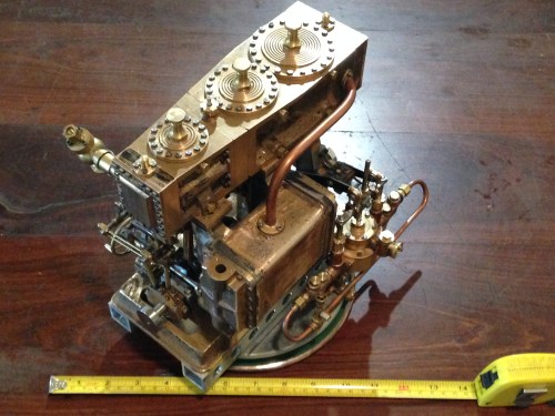
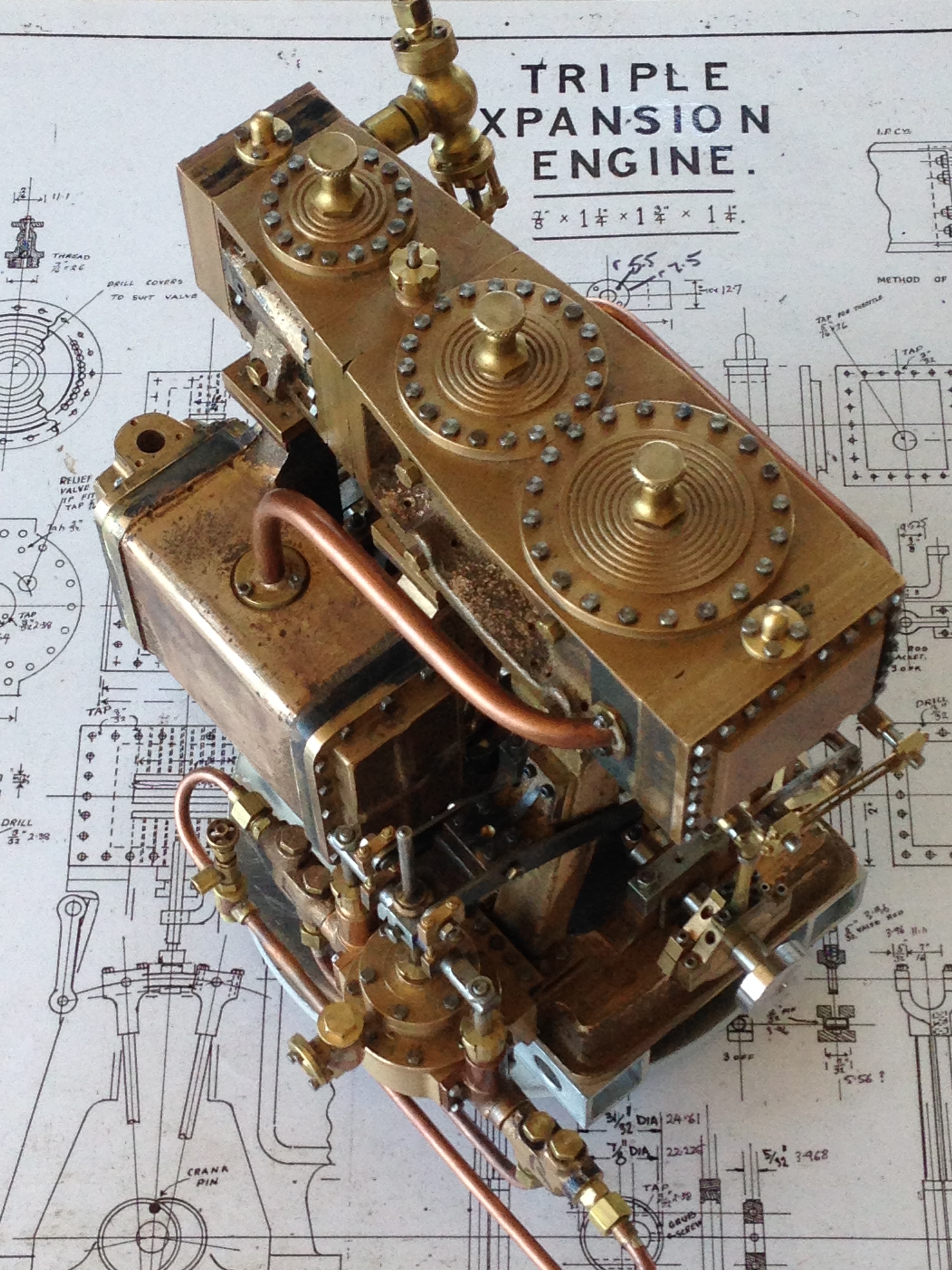
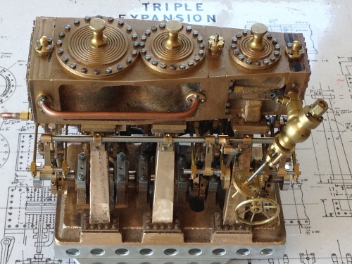
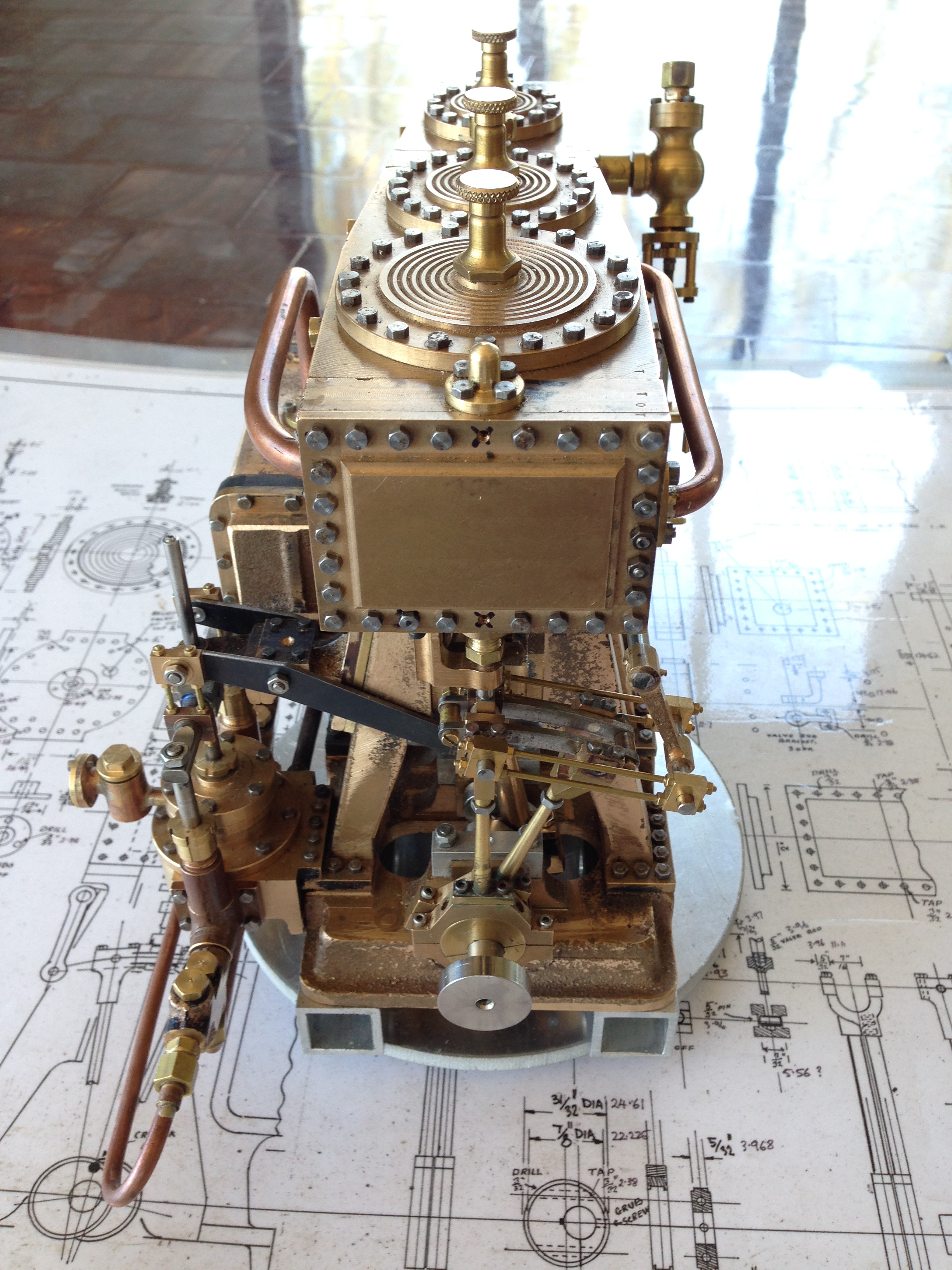
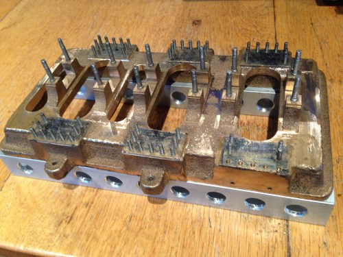
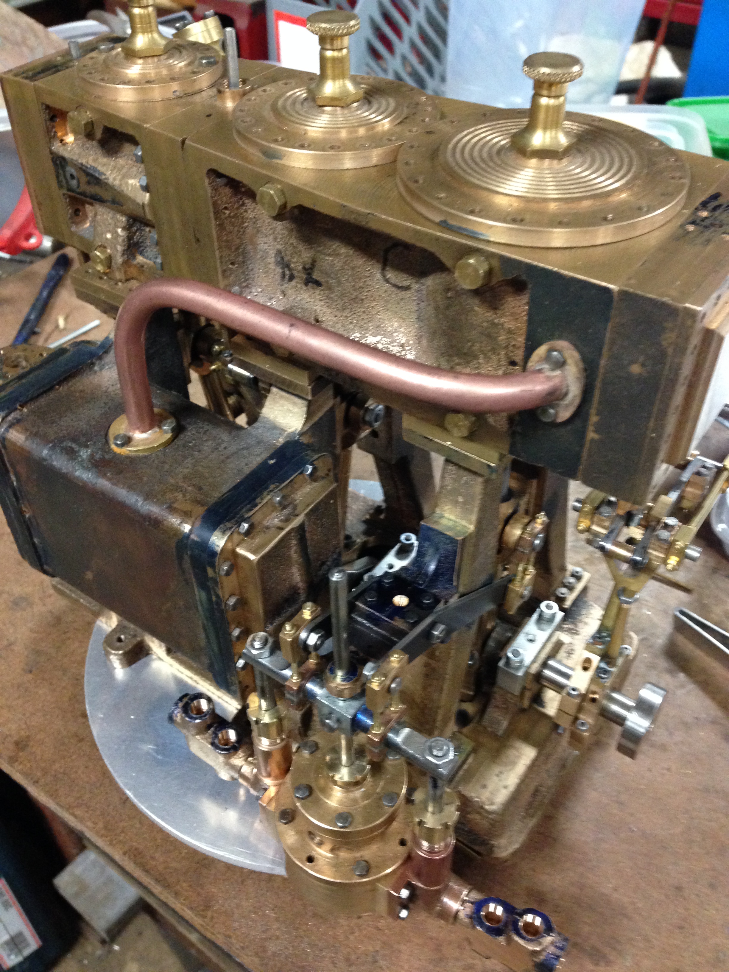
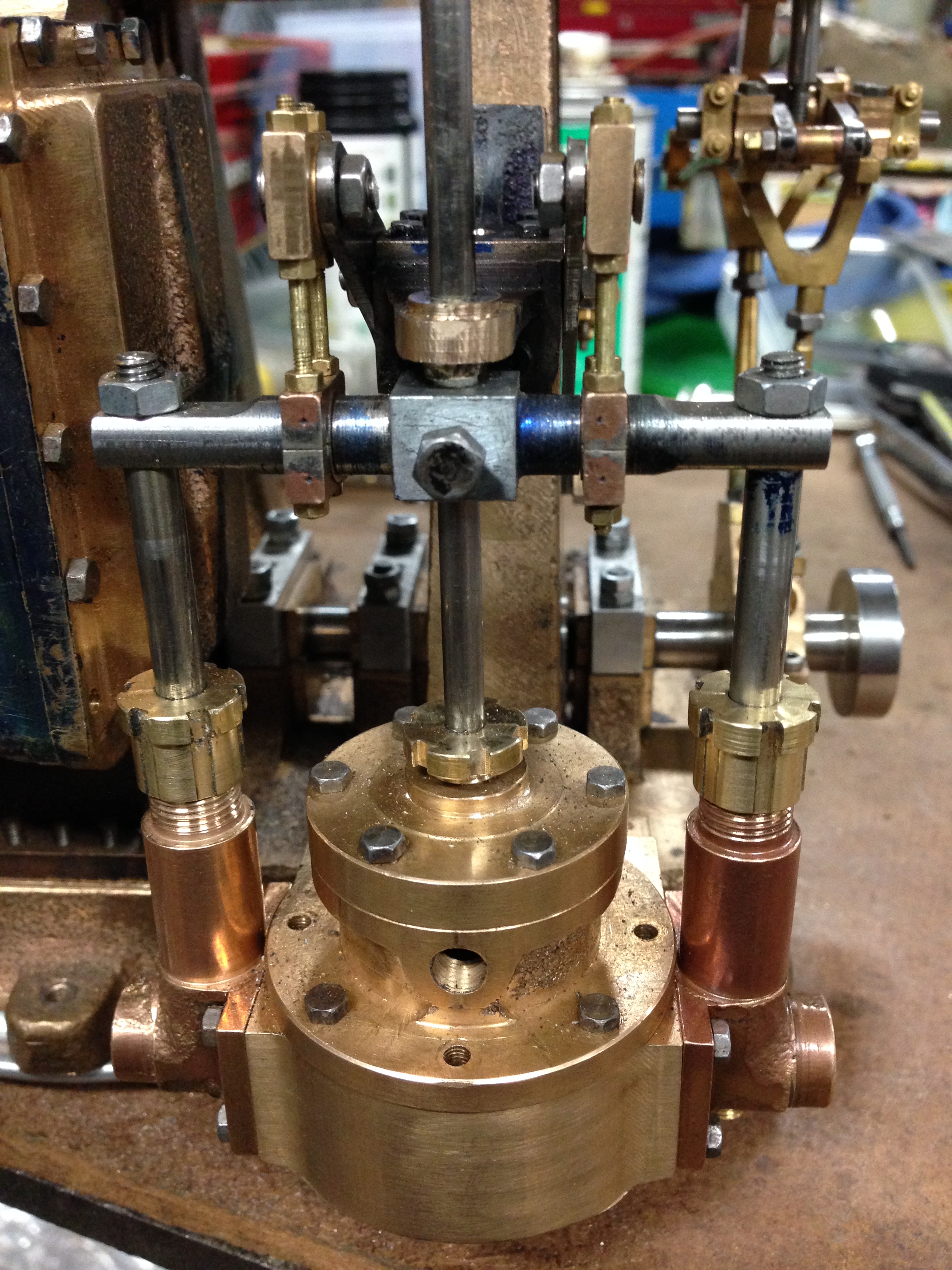
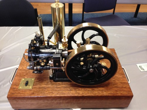
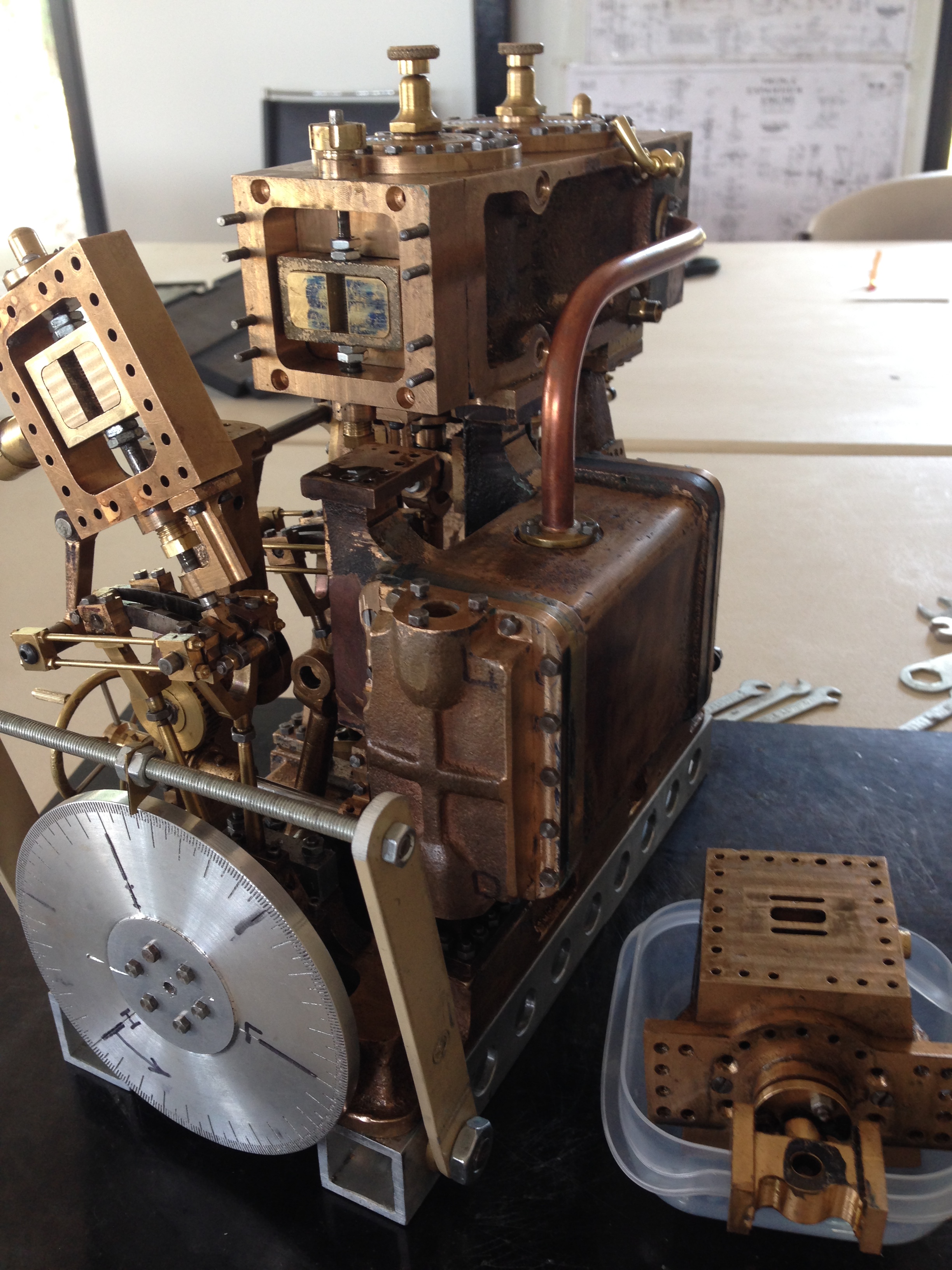
The engine needs to be pretty much completed and assembled.   Everything fitting.  Crankshaft rotating.  Valve rods tightened.  Stephenson’s reversing mechanism assembled and working. Cylinder drains installed.

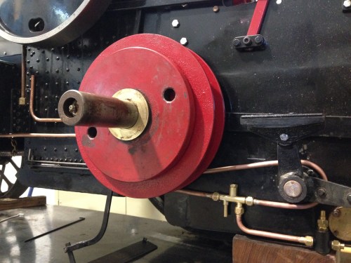
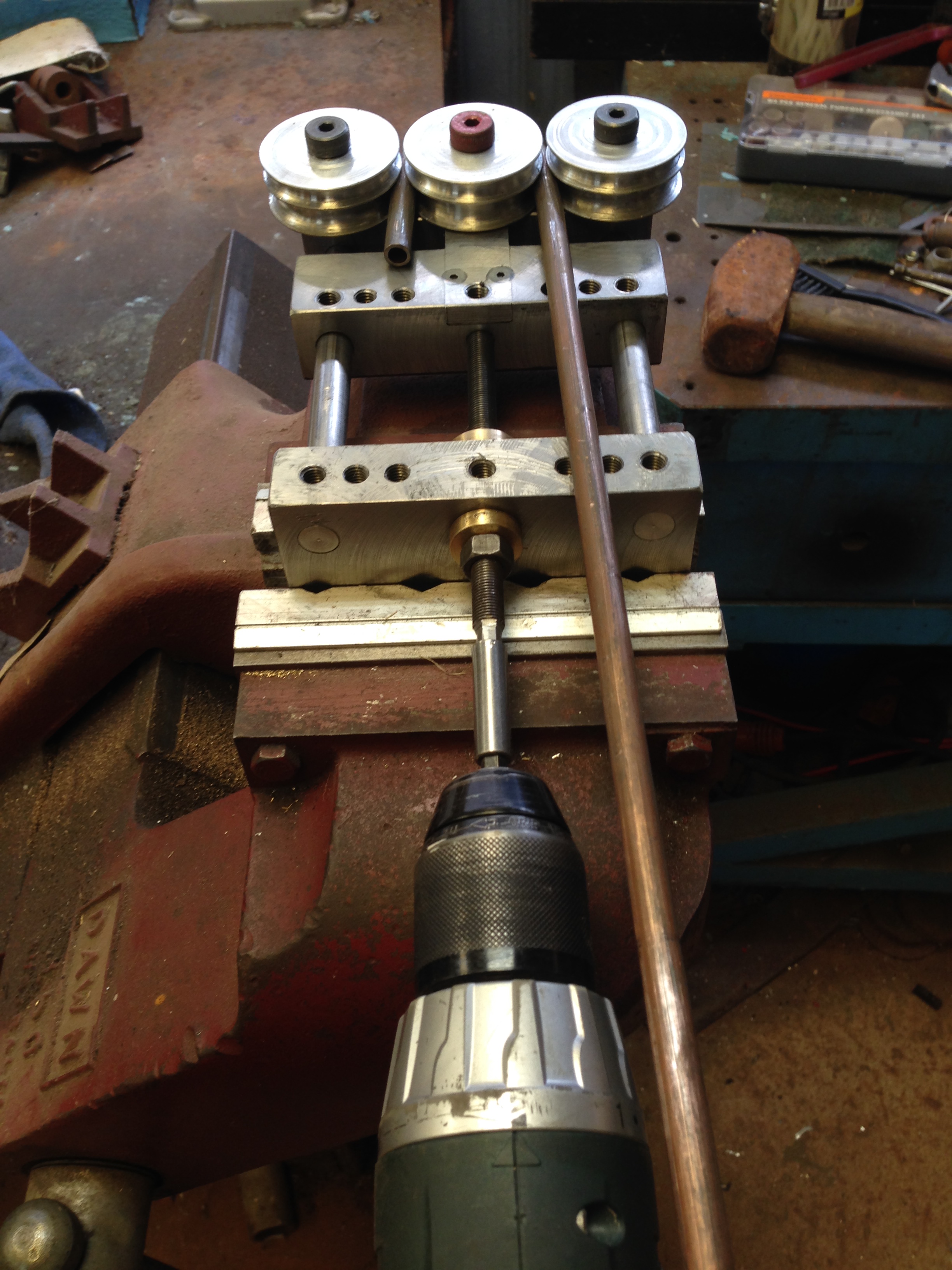
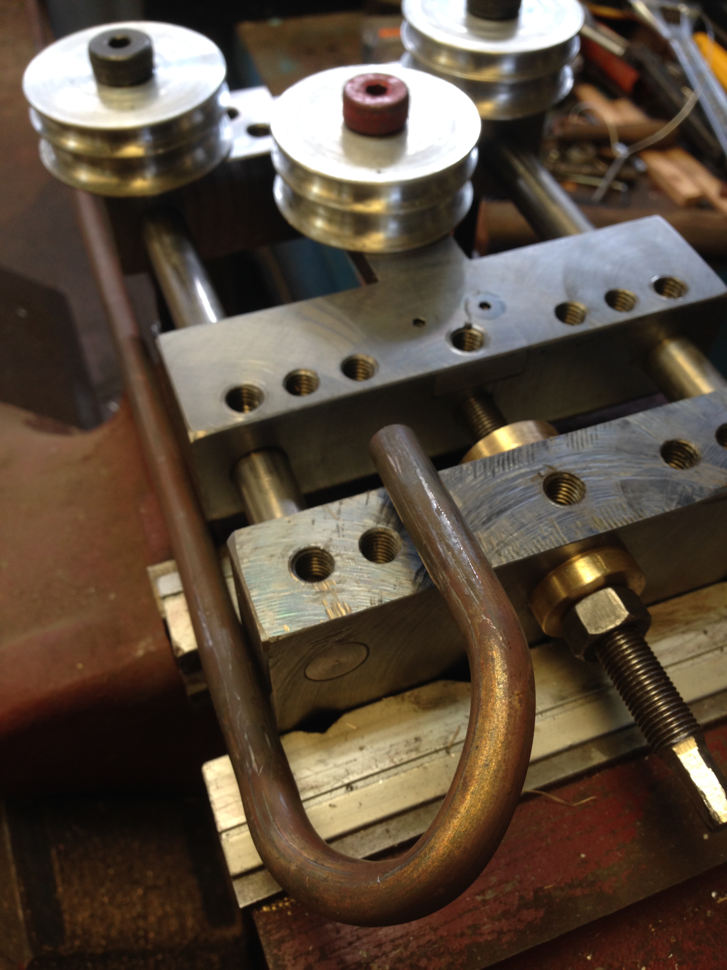
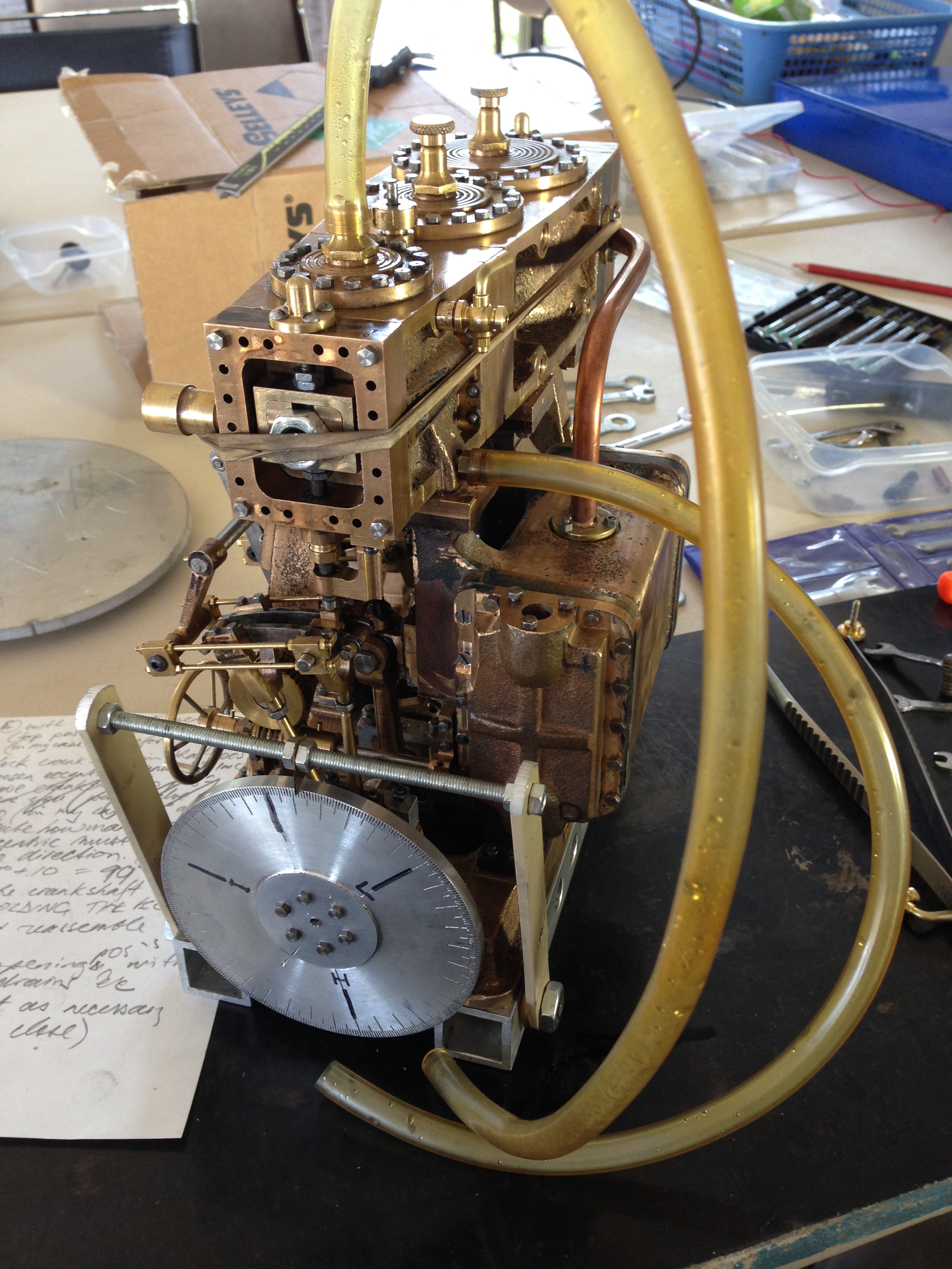
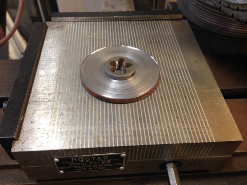
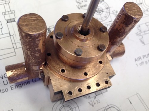
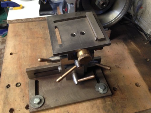
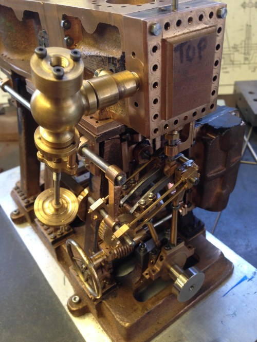
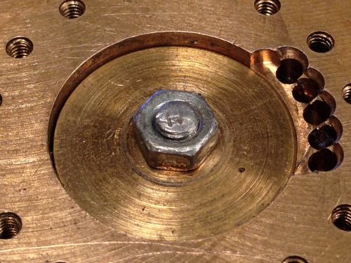
Next I suggest that you make or buy a 360 degree protractor, and attach it to the crankshaft at the high pressure end.  Like this.

IMG_6079

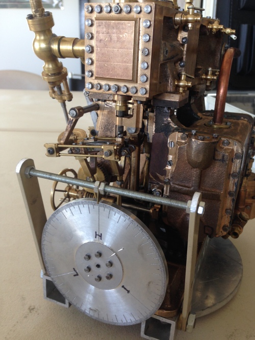
Note that top dead centre (TDC) of each piston is marked (H,I,L), there is a pointer, big marks at 120 degree intervals, and identifiable marks at 10 and 5 degree intervals.  I added a rotation arrow later, because it is easy to mistake clockwise and anticlockwise directions when making adjustments.

Next, decide where in the cycle you want steam to be admitted.  On expert advice from a marine engineer who is also a model engineer, I decided to admit steam at 10 degrees after TDC. (thanks Rudi!).  I also decided to cut off admission of steam at about 70% of the  power stroke. (pretty standard).

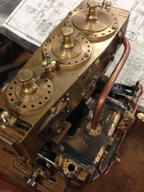
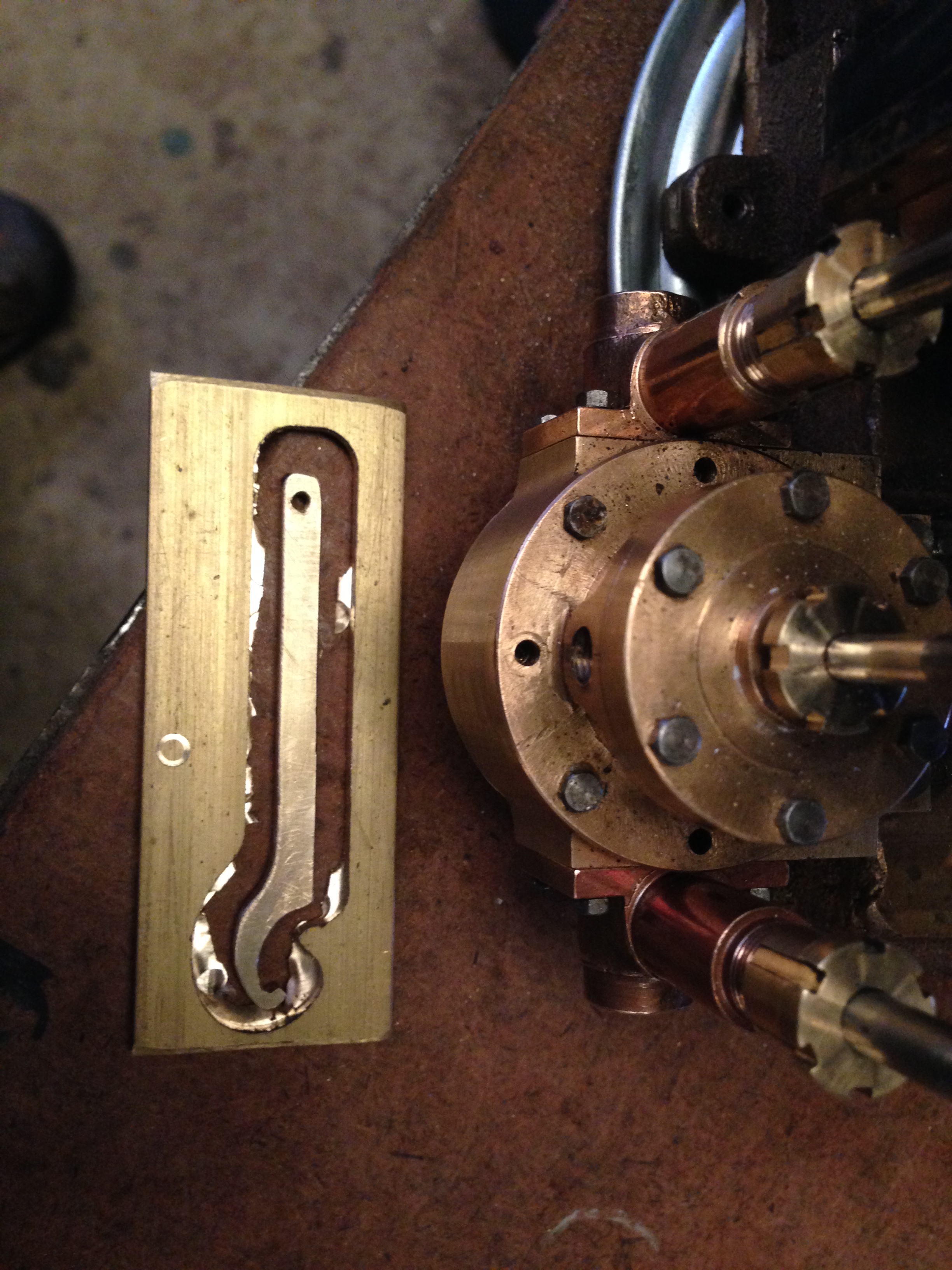
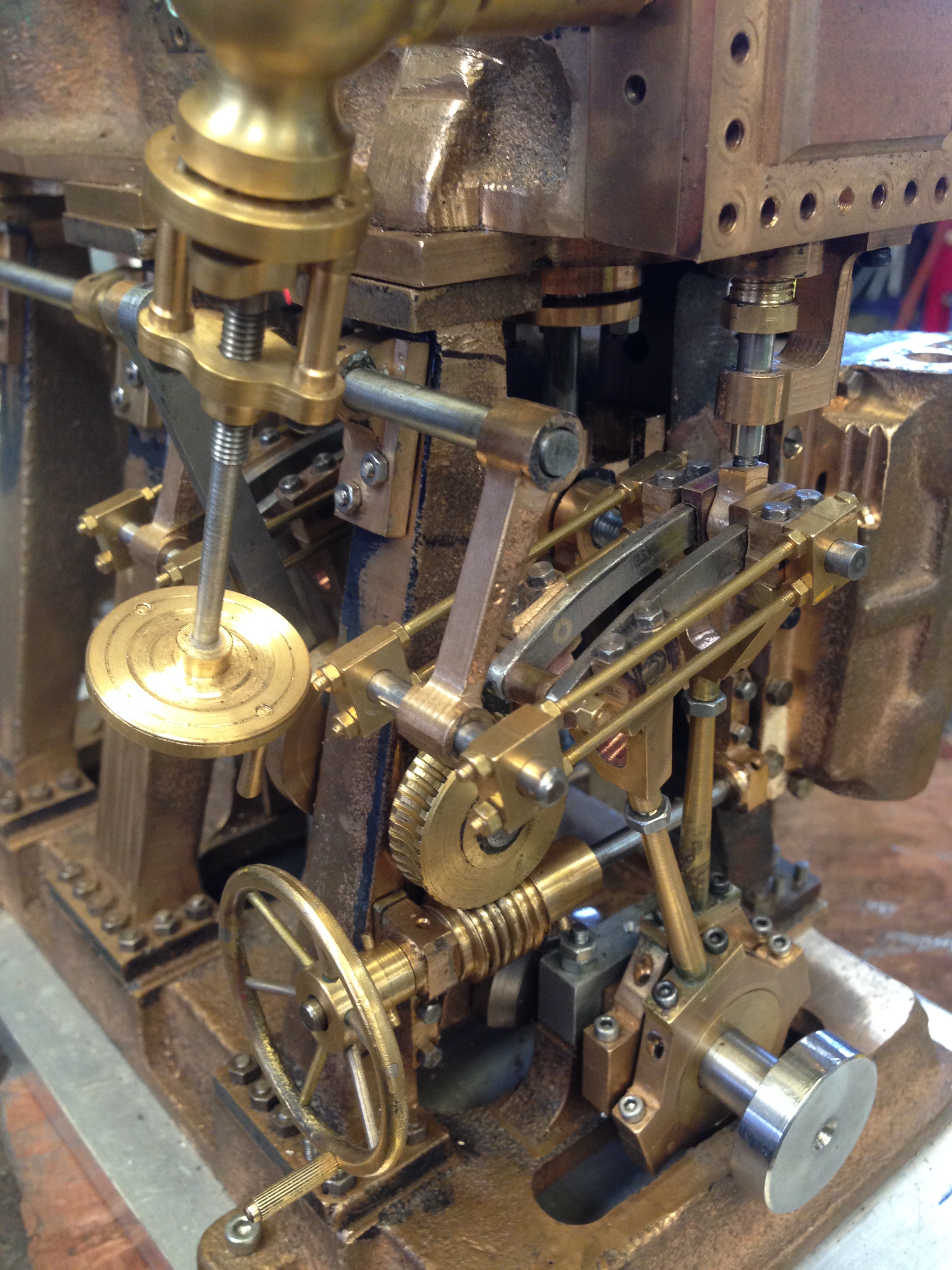
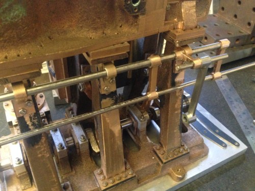
The easiest valve to time is the low pressure valve.  It is on the end of the engine.  It is the biggest, and there is not much engine stuff getting physically in the way.  Despite that, I decided to start with the high pressure valve.  It also is on the outside end of the engine.  The reason is that I wanted to follow the passage of the steam flow, in order to understand what was happening.  Each cylinder is timed separately, independently.  So the order is, high pressure, intermediate pressure, low pressure.  Forward direction first, then reverse, for high, then F & R for IP, then F&R for LP.

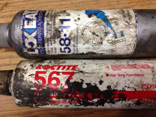
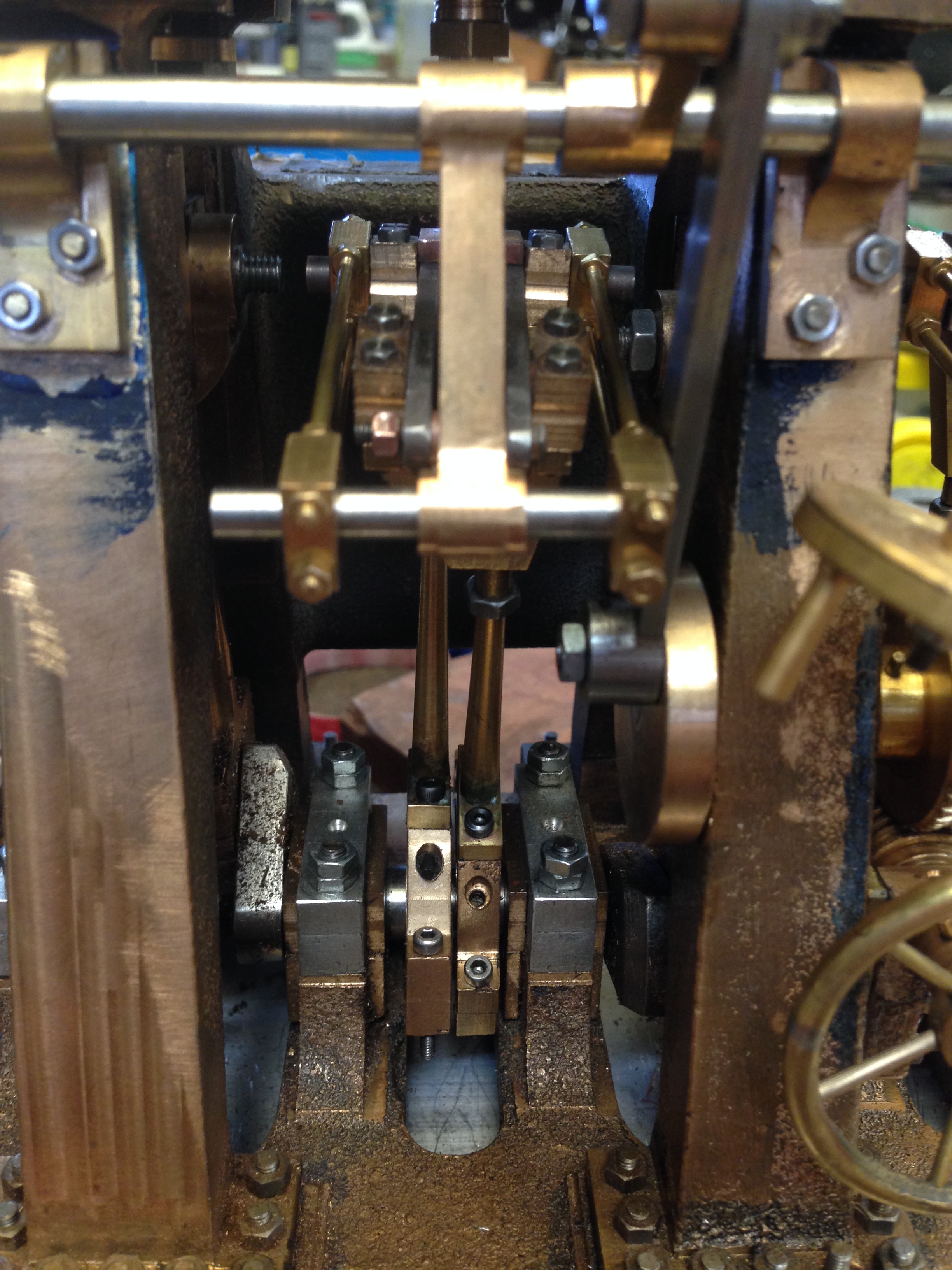
The timing is adjusted by 1. changing the distance between the crankshaft and the valve, usually by adjusting the length of the valve rod and 2. by changing the position of the eccentric on the crankshaft.

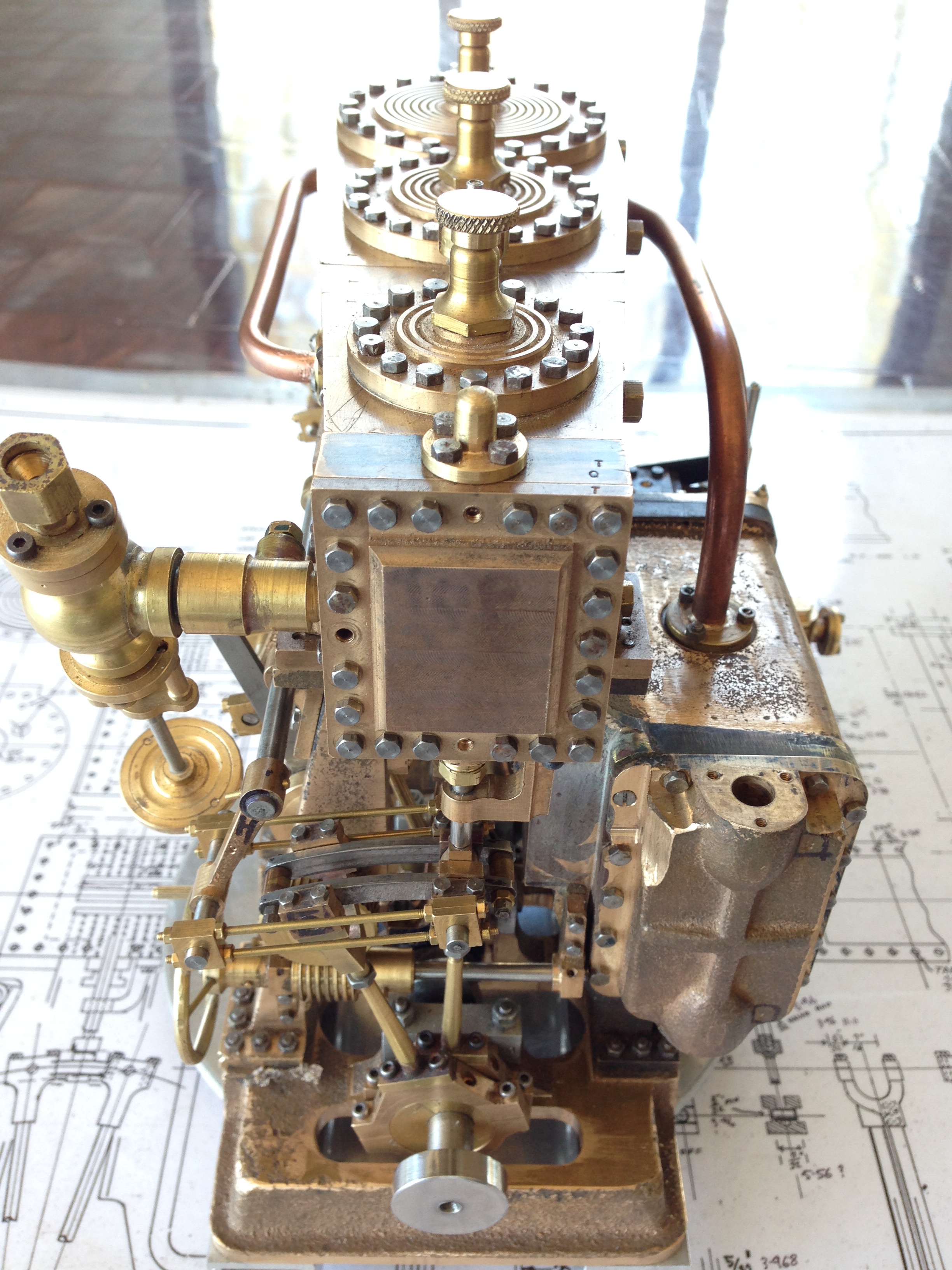
Firstly, the valve must move equally over the steam inlet slots. (the top and bottom ports). The point at which the inlet slot starts to open is noted on the protractor for both steam inlet ports.  The number of degrees before or after TDC is noted for the top port, and the procedure is repeated for the bottom port.   For the bottom port Bottom Dead Centre (BDC) is the reference point on the protractor.  The angle should be identical for TDC and BDC.  If it not identical the length of the valve rod needs to be adjusted.  On my machine, that was done by adjusting the nuts holding the valve rod to the valve bracket, but it could be the valve rod to the eccentric strap.

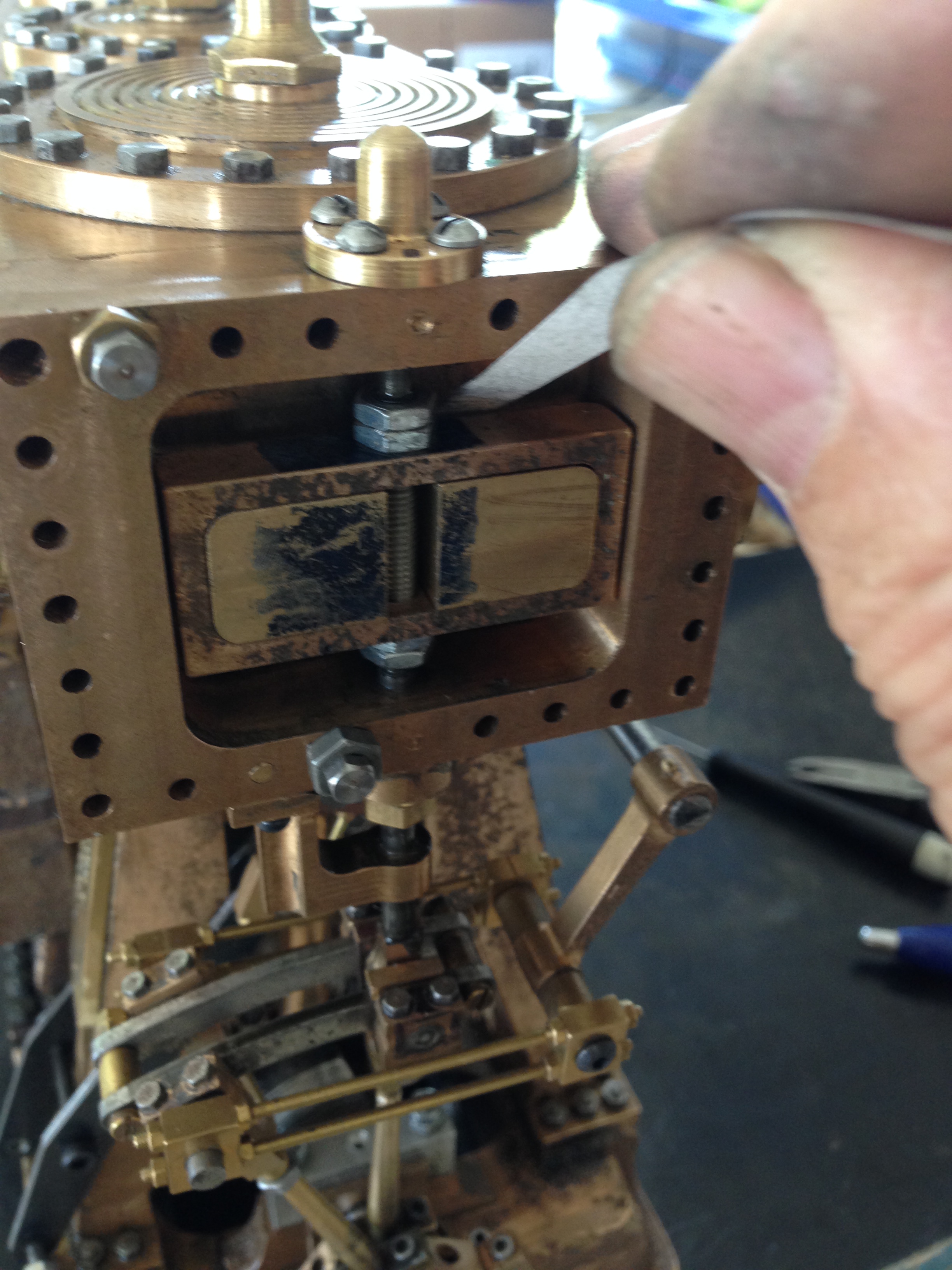
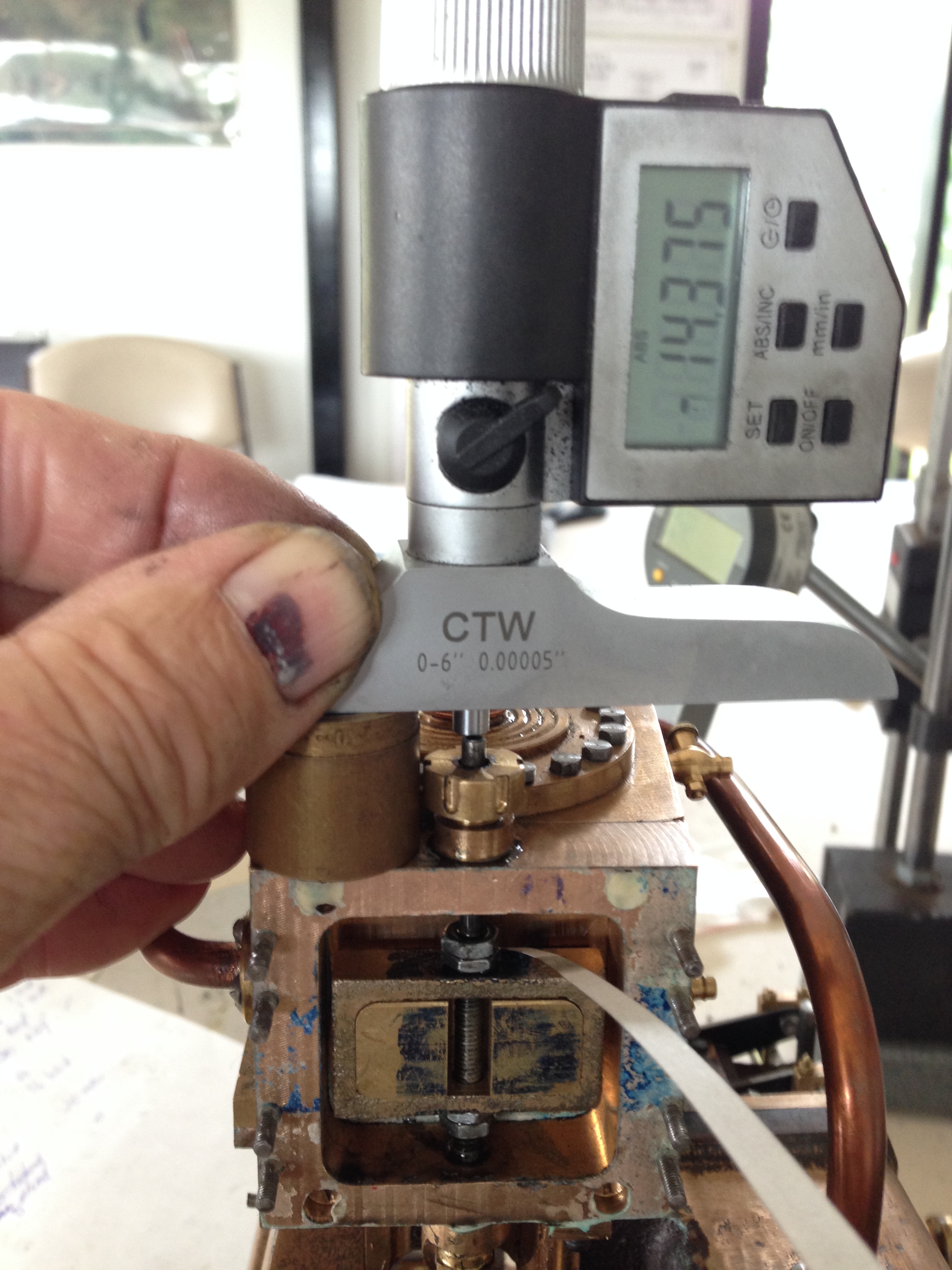
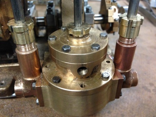
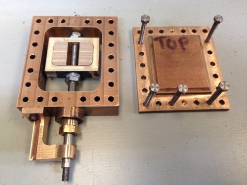
Determining the point at which the steam inlet port starts to open is easy.  Remove the valve chest cover, bolt the valve chest to the cylinder block, and rotate the crankshaft by hand until the port is obviously visually open.  Cut a sliver of paper 5-10mm wide, (I used copy paper), measure the thickness of the paper (0.1mm in my case), insert the paper into the open port, rotate the crankshaft to close the port until the paper is jammed, then while applying tension to the paper, slowly rotate the crankshaft to open the port, until the paper just starts to move.  At that point the port will be open by the thickness of the paper.

IMG_6139.JPG

The valve cover is off, a sliver of paper is pushed a centimeter or so into the port, the crankshaft is rotated to jam the paper then the crankshaft is rotated in the direction that is being adjusted until the paper is just released.   At that point the port is open by the thickness of the paper.  I calculated that 0.1mm was equivalent approximately to 3 degrees of crankshaft rotation.  So whatever was displayed on the protractor, I subtracted 3 degrees to get to the exact point of port opening.

when the valve moves exactly equally up and down over the steam entry ports, the point of opening is noted on the protractor relative to TDC of BDC, depending on which is being measured.

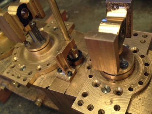
The eccentric grubscrew needs to be loosened, and  rotated on the crankshaft to bring the point of port opening to 10 degrees past TDC.  Then the grubscew is tightened.  BDC will automatically be correct if the centering process has been done accurately.

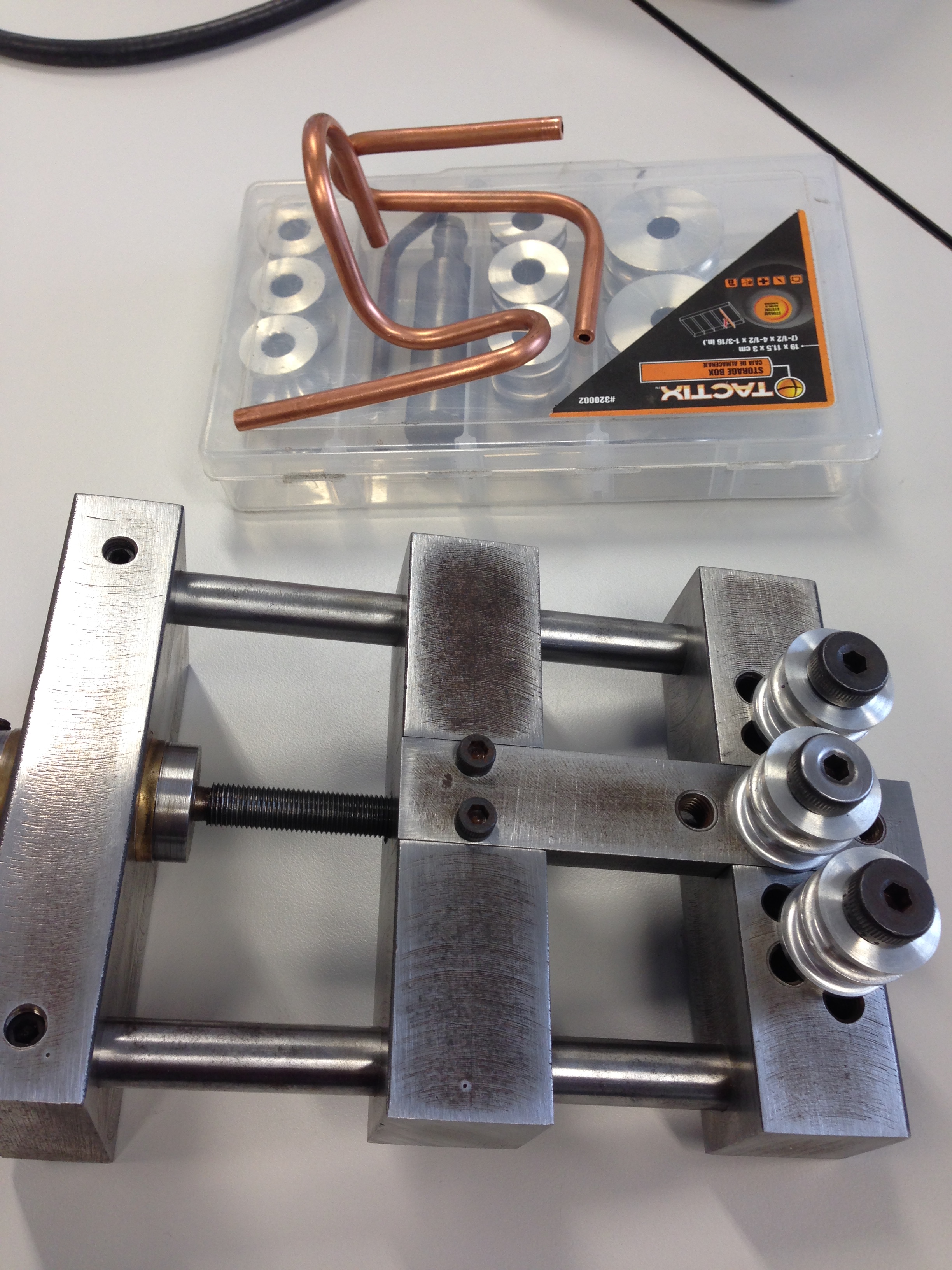
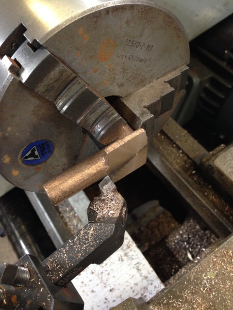
I had bored a hole in the eccentric strap to allow access to the grubscrew from underneath the engine.  That meant that the crankshaft had to be in a certain position to allow access to the grubscrew, not necessarily TDC or BDC or whatever.  That does not matter.  What matters is that the eccentric is rotated a certain number of degrees on the crankshaft.  I did this by using the Allen key to loosen the grubscrew, then using the Allen key to hold the eccentric fast, while rotating the crankshaft.  Then tighten the grubscrew, being careful to not move the eccentric.   The measurements need to be rechecked of course.   With practice, it is not difficult, and can be accomplished first go in most cases.

If this all sounds complicated and difficult, it really is not.  But I did need to make a record of every step and measurement and direction.

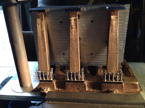
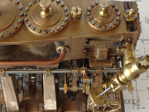
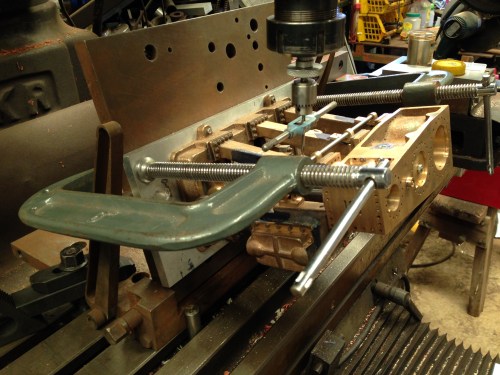
For the intermediate cylinder, the HP cylinder block needs to be removed.  The HP valve chest can be retained, just swung out of the way, retaining the previous settings..  You have to be careful, but this method does save a heap of bother.

IMG_6140.JPG

One thing I would suggest.  When the opening points of both IP inlet ports are determined and set, I suggest that before the HP cylinder block is reassembled, that the IP valve rod is measured above the IP valve chest.  And that the measurements are recorded and placed in a secure vault.  Those measurements can be used for any future adjustments of the IP valve, without the time consuming and very fiddly necessity of removing the HP cylinder block.

IMG_6165.JPG

I have determined the opening points for the intermediate cylinder using the paper method.  With the depth micometer on the valve rod above the valve chest, I am measuring and recording those positions, for possible future use.

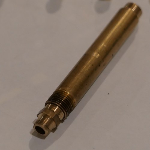
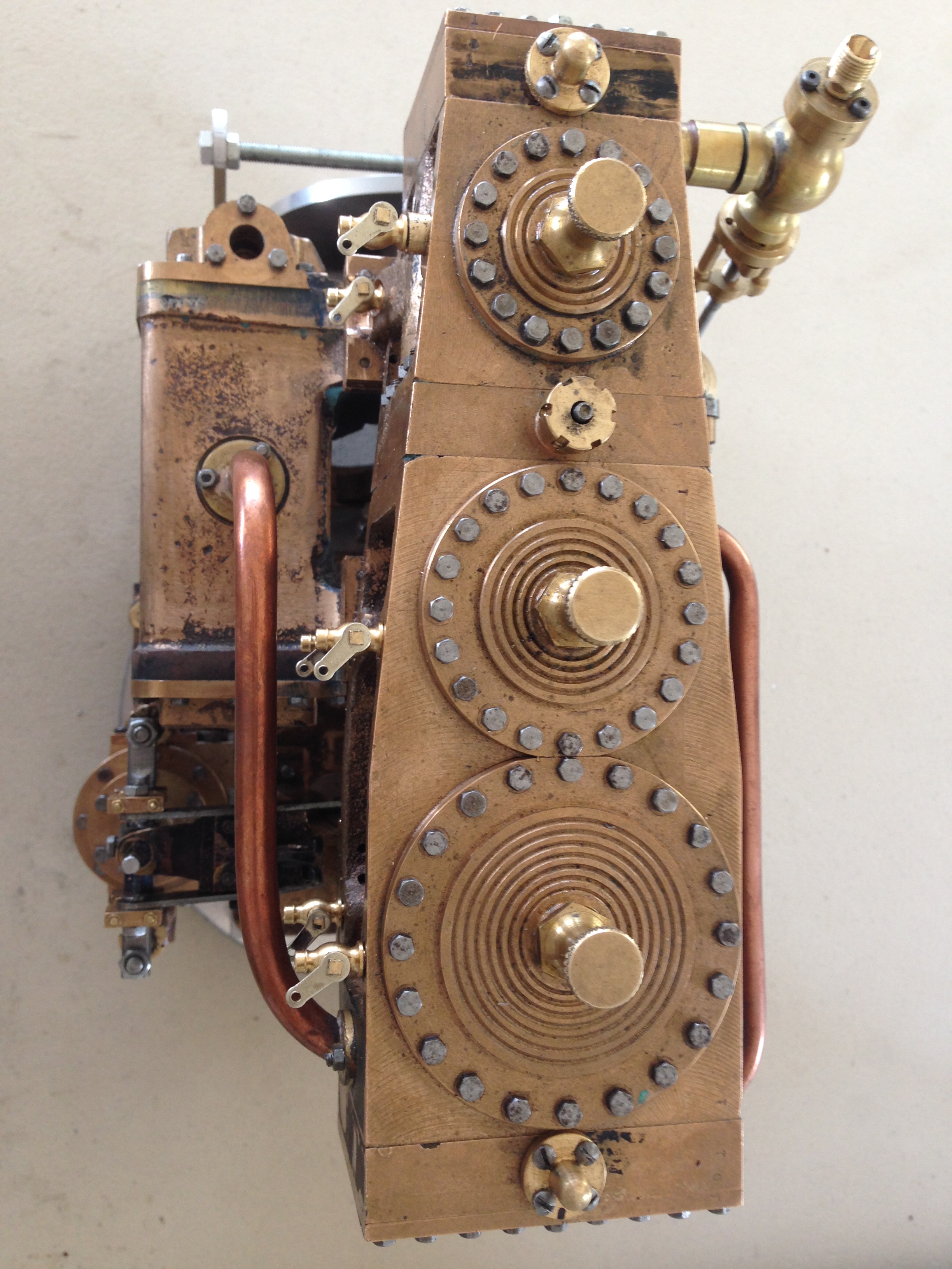
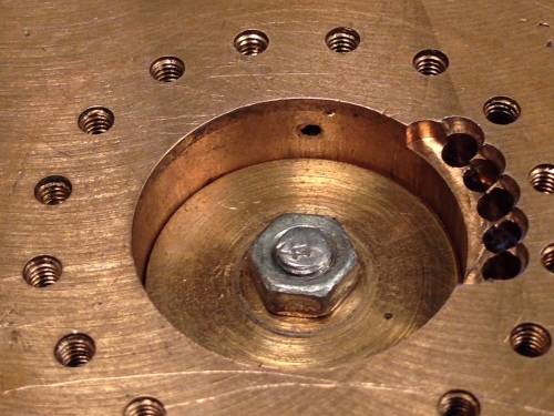
And I have a confession.  The next photo shows the HP upper cylinder drain, and the same view at top dead centre.  As you can see, at TDC the piston blocks the drain.)!*!)  Read on.

IMG_6203.JPG


IMG_6204 2.JPG

There is another method for determining the opening point of the valves.

IMG_6133.JPG

Plastic tubes are pushed on suitable points for the cylinder to be set, in this case the HP. The valve is pushed against the valve face, in this case with rubber bands.  One blows into the appropriate tube while rotating the crankshaft.  When the port starts to open, you can hear your exhaled breath coming through (if your hearing is OK, which mine is not).  The protractor reading is recorded, and used as before.   Note:  the drain cock passages MUST NOT be occluded by the piston at TDC or BDC.  In my case, this proved to be a problem, hence the use of the strip of paper method.

So, I hope that this is of some use.  If my description is jaberwocky, please send a message and I will try to help.    John.

First taste of steam for the MODEL TRIPLE EXPANSION ENGINE

I made a video of this first run, but I am experiencing great frustration uploading it, due to our totally pathetic Internet speeds here in Australia.  I will include it later in this post, but the resolution is way down.  I will upload a higher res version next weekend.

1 setup.JPG

Stuart Tankard’s superb gas fired vertical boiler, was also getting its first run powering a steam engine.

2 setup.JPG

We did not connect the condenser until later.

OK, so here is the video.  Again, apologies for the low res quality.

Model Triple Expansion Steam Engine. First taste of steam tomorrow!

I was very excited to see my triple running reasonably well on air recently.  But it was tight, and required a decent gutful of air pressure to turn it over.  But it did go!

Then it seized.

The cause was the intermediate cylinder valve rod seizing in its guide.  Probably a bit tight,and not getting any oil.

So I have loosened the gland, installed a displacement oiler, and made and installed a flywheel.  I also finished the pipework around the condenser.

IMG_6173.JPG

Displacement oiler top left, brass flywheel, and pipework.  The condenser on a marine engine would have been cooled with seawater, pumped with a separate pump, but I have used the 2 pumps on either side of the Edwards air pump.  In future I might install another pump.  The book “Marine Steam Engines and Turbines” has been been very useful.  

IMG_6179.JPG

I just like all of the brass and copper and components in this picture.

IMG_6170.JPG

The flywheel is too big for the scale, but my model does not have the weight and momentum of a propeller shaft and propeller, so a sizeable flywheel seemed appropriate.  Later I will add some gear teeth on the flywheel and a cranking handle on a removeable pinion, which some medium size engines had to assist with cranking to a starting position.  

So, tomorrow I will hook my triple up to Stuart Tankard’s vertical boiler, and see what happens.  I am sure that steam leaks will be revealed.  Hopefully there will be a video worth posting!

TRIPLE EXPANSION MODEL ENGINE- FIRST RUN (air)

This is a short video of the first run of the Bolton9 Model Triple Expansion Steam Engine, which I have been building on and off over the past 3 years.

The video is a bit shakey, because it is taken on my hand held phone while I am using he other hand to operate the controls.  I really did not expect the engine to work!

It runs a bit roughly, and is still quite tight, but settles down in the final few seconds.

It is not running very smoothly, because it is on air rather than steam, and because it is probably only powered on the high pressure cylinder, and maybe a bit on the intermediate, and not at all on the low pressure cylinder.

The next day it would not run.  Very frustrating.  I suspect that one of the eccentrics slipped on the crankshaft, and threw the timing out.  Not the easily accessible low or high pressure valve, but the intermediate one, which needs another teardown to get to it.

But Hey!  It will work.  I can see the light at the end of the tunnel.

One of my readers has requested a description of the triple engine timing procedure, so that will appear on this blog soon.  Unless you have a particular need for the timing info I suggest that you give that post a miss.

Back to the Triple Expansion Steam Engine

IMG_6013

I installed these cylinder drains on the triple, but was not satisfied with their appearance because they looked too big.   So I bought some of a different pattern from Reeves UK.

IMG_6077.JPG

The new cylinder drains are smaller, and have a handle which is suitable for joining all 6 drains to one control handle.

IMG_6071.JPG

The new cylinder drains are a more realistic scale.  I suppose that I should have made them myself.  

IMG_6080.JPG

From above.  Getting them to line up was a fiddle.


IMG_6079.JPG

The crankshaft protractor now has a (temporary) pointer.  When the timing is finally adjusted, the protractor and pointer will be removed.  I am planning to make and install a crank positioning gear and pinion and lever.

IMG_5680.JPG

The crank positioning gear and pinion shaft on the full size, ship’s triple expansion steam engine at The Geelong Showgrounds.  It is on the low pressure end of the engine.  I will make something like this to act as a flywheel on my model triple.

More Wierd Stuff

Since my “Strange Lights over Geelong” experience I have been looking at all sorts of weird posts on YouTube.  UFO’s, crop circles, megalith structures, evidence of buildings on the moon and on Mars.  There is a mountain of information out there, and while a lot of it is lies and rubbish, some is harder to dismiss.   It is not inconceiveable that Governments have information which they are witholding from the general populace, about aliens, UFO’s, ancient civilisations and so on.  Indeed, there are YouTube interviews with ex astronauts about UFO’s on the moon, and ex government ministers and officials about UFO’s and aliens, and Rothwell.  It may well be that the current increased talkativeness is due to a recognition by governments that they can no longer keep a lid on the previously secret information, so they are gradually allowing people to talk.

One line of posts which I have followed is evidence that something is going on in Antarctica.

And one source of information is Google Earth.  One post related to a strange set of giant “steps”.  I checked on the post information by checking the coordinates in Google Earth.

staircase.jpg

Look at the middle of the photo.  That series of “steps” does look unusual.  You can check on this yourself by entering the coordinates on the photo into Google Earth.   The “staircase is about 2.5km long, with each step about 250 meters.

Anyway, to continue with my story, as I was zooming out from this point, I noticed a bright shape about 138km towards the south.

Antarctica #4.jpg

The object which caught my eye was the white rectangle above the word “Coast”.  This section of Antarctica is directly south of Western Australia.  The rectangle is about 380 km from the coast.

And this is what shows up on Google Earth as I zoomed in.

Antarctica 6 Jan 2018 #2.jpg

The image is from 1999.  The black rectangle is 21 x 7km…  Quite a size!   I am unsure what the bright white is.  Possibly sunlight reflecting off a shiny surface.  Or a rough attempt at concealing the rectangular area?    This is at latitude 70.2 S, longitude  87.2 E.

Antarctica 6 Jan 2018.jpg

Also, there is a faint streak from the rectangle heading about 100km to the east.  It is also 7km wide.     The staircase area is also visible to the north.

So that is it.  I can find no reference to this structure, but if anyone knows anything about it, please enlighten me.   If you have any interest in this weird stuff, you might the posts on YouTube by SecureTeam10 worth watching.

I am heading back into the workshop tomorrow.  Installing a steam powered boiler water injector on the Fowler traction engine, and bit by bit, finishing the triple expansion engine.

I have installed the new AC Servo motor to replace the spindle motor on the Boxford 125TCL CNC lathe, my expert friend Stuart Tankard has wired it up and reconfigured Mach3.  I am delighted to report that it has vastly improved the CNC lathe.  Will post some pics in a day or two.

Triple Expansion Steam Engine Cylinder Cocks

Some further progress on the triple.

I bought cylinder cocks from Reeves UK, and the picture shows them fitted.  In case I eventually install a mechanism to open all of the cocks simultaneously, they are in straight line, which necessitated making extension peices for the high pressure cylinder cocks.

The handles required bending to clear the pipework.

The cocks look a bit strange to me.  Too big, and the handles are wrong.   I am thinking about making a set from scratch.  But that can wait.

IMG_6013.JPG

Drain pipes from the cocks will be installed at some stage.  Still deciding where to run them. And whether to join them into a common trunk.

FullSizeRender 7.jpg

The engine turns over by hand, but it is still a bit stiff.  There was a tight spot which took many hours to locate.  It turned out to be a valve rod thread which was about 0.5mm too long, touching the inside of the high pressure valve chest.   Fixed in a jiffy.

I hooked up the engine to a small compressor at 30psi, but general stiffness prevented the engine from rotating.  So I gave it an hour being rotated in the lathe at 200 rpm.  It is noticeably more free, and getting very close to working.  The valve timing is approximately correct (checked by my expert friends Thomas L, and Rudi V), but will need fine tuning at some stage.

Running in the Triple Expansion Engine

The Bolton 9 engine is assembled, almost completely.  The valves are approximately correctly timed.  I can turn it over by hand, just.  There are a few tight spots.

So today I mounted the entire engine in a lathe, oiled all bearings and slides, and tentatively ran it for a few minutes.   The lathe was set at 60rpm, in back gear.

All seemed OK, so I ran it for about 30 minutes.   Then increased the rpm to 90 for another 30 minutes.  After that the tight spots still exist, but much less pronounced.

IMG_5932.JPG


I kept a check on bearing temperatures with a laser thermometer, and none were running more than a degree or two different from any others.

The test did show that a low pressure cylinder drag link is touching the condenser, and will need some relief.  Also the high pressure cylinder eccentrics need to be repositioned a little on the crankshaft.  But nothing major.  And it was very nice to see everything moving in quite an impressive manner.

I will upload a video when the upload speeds are reasonable.


2 Triple expansion steam engines.

More Triple Photos

Reader Richard suggested that I include a ruler in some of the triple photos, for a sense of scale, so here it is.

It is approx 300mm long 200mm wide and 270mm high.  Weighs 12.4 kg.

IMG_5669.JPG

Triple Expansion Engine Update

Well, almost another whole year has elapsed, and still the triple is not finished.  Come December, and that will be 3 years that this project has occupied my thoughts and workbench.  With a few other projects in between.

Last week I assembled the components, in preparation for the Geelong Show.  GSMEE is a bit light on for new models, and it was suggested that the triple might fill some shelf space, despite being unfinished.

So I bolted it together.  All 429 fasteners!  And stood back and admired it.  It really is quite impressive, complex, and interesting.  So I took some pics.

IMG_5657.JPG

This is the condenser side, and the Edwards pump

IMG_5659.JPG

The other side is a bit lessy fussy, showing the steam inlet valve, the Stephenson’s links, weigh shaft  and controls.

IMG_5662.JPG

And the top, showing some of those 429 fasteners,

IMG_5665.JPG

The high pressure valve chest cover.  I will fill those holes where bolts cannot go.

IMG_5664.JPG

And the low pressure end, and links for the pump.

IMG_5660.JPG

And a close up of the steam valve and weigh shaft.

Not quite ready to run it yet.

It needs side covers for the cylinder block, drain cocks for the cylinders, and general freeing up.  It is still very tight.

Not to mention painting.  I expect that I will paint this one.   No idea of colours yet.

TRIPLE FINAL(?) ASSEMBLY

Just one photo to show that I have not totally ignored the triple expansion marine engine.   I have started to re-assemble it, having made almost all of the components.  But there were quite a few finishing tasks put aside until later, which I am now tackling.  eg lubrication points.  I suspect that this will not be the final teardown and assembly.

IMG_5233.JPG

The gunmetal base, with main bearings and crankshaft installed.  The eccentrics are not finally positioned.  

And some reminder photos from 2 years ago, of making the crankshaft.

IMG_2608

The centres were drilled on the CNC milling machine, after the locating the top of the bar

IMG_2638

Turning the second big end bearing.  Note the packing to support the crankshaft after the first big end had been turned.   The main bearings were turned last.

IMG_2641

The finished crankshaft.  Not much remains of the 51mm stainless rod.

A Base for the triple, and some oil holes…

Thinking about the options for a base for the triple expansion marine steam engine..

I looked at every photo I could find on the net, and thinking about whether I want to be historically accurate, or just really solid, or a bit interesting with an historical flavour.

At this stage, the decision is not set in concrete, but I am going with the last option.  Photos later in this post.

But first, I have pulled all of the major components apart, and I am spending time doing a few of those jobs which I had been avoiding because they are difficult and imprecise, and if they go badly it will be a major disaster at this stage.  Like drilling the oil holes and wells for the big ends.

Nothing precise about this.  The con rods and big end shells and bearings have been painstakingly machined, and I do not want to think about remaking them if I stuff up.  And drilling into curved surfaces, with a 1.5mm drill bit…

IMG_5183.JPG

That thread is 3mm dia.  The hole above the nut is the oil way, 1.5mm dia.  Very tricky and too anxiety provoking to be thinking about a video.   Amazingly, it all went well!   I now have 2 oil holes for each of the 3 big ends.  I will need to fill the well with oil with a medical syringe and fine needle, but.

IMG_5172

The crankshaft, turned from stainless steel a year or two ago, and the conrods.  The big ends now with lubrication points.

And here are the major engine components, after partial disassembly.

IMG_5170.JPG

At top left is the condensor, then the cylinder block in 2 parts, then the steam supply valve.  The square section tube is going to become the base.  And so on.  You get the picture.  I will count the bits at some stage.

Then I cut and drilled the square section aluminium tube for the base.

IMG_5182.JPG

The cast base of the triple, with main bearing studs and column studs in place.  All sitting on the square section alu.  Have not decided whether to bolt it together, or just Loctite it. 

Those holes in the square section were drilled and chamfered on the CNC mill.


Triple Expansion Steam Engine Pipework.

I am close to disassembling the Bolton 9, before gradually reassembling it in preparation for running it on air then steam.  Most of the components have now been made.  Most recently I completed the pipework associated with the Edwards air pump and the twin water pumps.

IMG_4997

This is the combined air and water pumps, and new pipework.  Most joins are silver soldered, but a couple are Loctited.  Loctite should be adequate.  These components will not get super hot.

IMG_4999

This valve is one of the few components on this engine which I have not personally made.  This one came from the effects of the late Harry Close, who was a valued member of our Model Engineering Club.

IMG_5002

The pipework adds to the overall interest , yes?  It will look good when polished.

IMG_5001

And the “tails” for the valve rods, which are attached to their respective steam chests.  The BA7 bolts are a bit oversized for the job.  The intermediate cylinder tail screws into place.  I am not sure why it is different from the other two.

So now I am making a list of tasks which need to be completed when the engine is taken apart, hopefully for the last time before it is run.  The list is not complete, and so far it runs to 3 pages.  Mostly like fixing parts which interfere with each other, and freeing up tight bearings.

I will take some pics of the components.

Cutting a thread up to a shoulder

A problem with some thread dies is that they have such a large “lead in” that they are unable to cut a thread up to a shoulder.

fullsizeoutput_19d9.jpeg

A 3/8″ x 32tpi die.  Note the large lead in taper.

This results in the thread stopping a long way from the shoulder… undesireable in some situations.

IMG_4984.JPG

This is a thread made with the die in the previous photo.  I wanted it to go right up to the shoulder, but this is as close as it gets.  About 2mm gap.

IMG_4987.JPG

The screw in this upsidedown photo does not allow the shoulder to seat properly.

The solution?  Modify the tool.

IMG_4988

Here is the tapping die, held onto a magnetic chuck, within a machined steel disc to increase the magnetic attachment force.

IMG_4991

So I ground off the top 1-2mm of the die.  My surface grinder is out of action, so I used the tool and cutter grinder.   A bit rough but it worked.

IMG_4993.JPG

This is the die after grinding the surface.  Note that there is no lead in.  I ground the unlabelled face so I did not lose the specs of the die.

IMG_4994 3.JPG

And the screw after using the modified die.  The thread  now goes right up to the shoulder.  Incidentally, this is a zoomed photo using an iphone.  Not bad?

So that does the job.

The downside is that in future the thread must be started with the unmodified side of the die, and finished with the modified side.  Adds some time.  And the die is thinner and a bit weaker.

A pity that the dies are not manufactured with one “no lead in” face.

The particular set of ME dies will now all be modified in the same way.


A Turntable for the Triple Expansion Engine.

I have not weighed the Bolton 9 triple expansion steam engine, but I would guess that it is 20-25lb.  (weighed it.  25.5lb)

Access to the various bolt on bits and pieces has become increasingly difficult and tricky, and involves frequent repositioning of the engine.

I removed the bolt on base and that has improved the situation a bit.

Then I had a brainwave, thought bubble, inspiration  whatever, and I tried a ball bearing turntable….   you know….. one of those Chinese restaurant middle of the table gadjets.

It is incredibly useful!

Here are some pics and a video showing it in place;  just a demo of the engine at its current (unfinished) stage.  I think that the turntable might  become a frequently used tool for heavier models.

triple apr7.JPG

The Bolton 9 on the turntable

triple water pump valve.JPG

And the latest additional bits…   non return valves on the water pumps.

Edwards Pump for the Triple Expansion Steam Engine

The triple expansion steam engine has been progressing, again.  I started this project over 2 years ago, but I have taken many breaks, some prolongued.  One break lasted over 6 months while I made some cannons.

I cannot remember when I made the Edwards pump for the triple, but it must be over a year ago.   In the past few days I have returned to it, finalising the mounting to the engine, and joining the driving levers to the pump and the engine.

The Edwards pump creates the vacuum in the condenser chest.  It is an air pump.

Attached to the Edwards pump are 2 water pumps, which return condensed steam as water, to the boiler.  At least that is what I understand from the descriptions.  It feels a bit odd, making these components before understanding what they really do.

triple-expansion-engine-1-22

The Edwards pump is the central cylinder and rod.  The water pumps, bolted to the sides, are just lumps of semi machined cast gunmetal at the stage this photo was taken.

triple-expansion-engine-1-17

The step before the above picture, where the base of one water pump is machined.


IMG_4918.JPG

The Edwards pump, and the 2 water pumps, almost finished, attached to the engine.

pump spanner.JPG

There is no clearance between the pump gland and the condensor, so the intitial hexagonal glands which I made (not shown) were unuseable.  So I made these cylindrical glands which required a tiny hook  spanner to tighten.  The hook spanner was made on the CNC mill from 1/8″ brass plate.  A little filing was required to shape the hooked tooth.  Works nicely.


IMG_4917

The pump unit, lower left, attached to the engine.  Actuating levers driven off the low pressure cylinder (not yet connected).

IMG_4915.JPG

The pump unit viewed from the side.

So I am at the stage where I would like this project to be finished, so I can get on with other projects.  It feels like it is close because there are very few castings remaining in the box.  But I know that the entire engine has to be disassembled, and painstakingly reassembled, freeing up some of the tight parts so it will turn over more easily.  Then the steam pipe hookups and valve timing.  Then hopefully, a video of it running!

Harold Hall Grinder Rest – modification; and triple expansion update.

Harold Hall has written many articles and several very useful books about metalworking, using a lathe, using a mill, and much more.

Recently he has been posting videos on YouTube.

He is a very knowlegable, dignified, elderly gentleman.  His books are precisely, beautifully written, and the plans and projects are excellent.  I have made quite a few of the project pieces in my quest to learn as much as I can about machining metal.

I came across his Youtube videos quite recently, and have been enjoying them.  One of them was about his grinding rest.

I made 2 of the HH grinding rests from plans in his book, and they have proved to be useful, reliable, and compact.  Here is a photo of one of them.

IMG_4883.JPG

The original HH plans specify that the footprint of the base is much smaller than I made it.  This one is 200 x 100mm.   The larger footprint adds some extra stability (IMO), and the slots permit the grinder to rest distance being easily adjusted.  It is a bit grimy because it is used frequently.  Polishes up quite nicely.

In HH’s video he mounts the rest on a metal plate, joined with a couple of switchable magnet bases.  Here is a link to HH’s Youtube video.

And in case you are wondering what has happened to the triple expansion engine, I have been working on the reversing mechanism.  The intermediate cylinder reversing curved slide would not fit into the available space, so I removed it, silver soldered in a new end, and ground it several millimeters shorter.  Then reinstalled it.   It is still a mm or so too long but I think that it will do.

IMG_4878.JPG

The high pressure reversing mechanism on the right, and the intermediate hiding behind, on the left of the pic.

IMG_4880.JPG

The intermediate cylinder valve rods and eccentrics.   Rather difficult access.

Assembling the Triple

img_4705

I got this far in assembling the model triple expansion steam engine, then lost courage and put it aside (again).  You can see the high pressure steam chest labelled “top”, the steam valve and handle, the drag links and levers for the reversing mechanism for the high pressure cylinder, and the worm and gear and control wheel for the reversing mechanism.   The reversing levers will need pinning with taper pins when the correct positions are finalised.  The short rod in the middle of the pic is temporary.  I need to make those properly.  The drag links clash with the condenser cover.  That was predicted in Bertinat’s notes.  The cover will need some material removed.  Slowly progressing, but taking frequent breathers.

The high pressure mechanisms are the most exposed, and easiest to access, and they were very tricky, and not yet compeletely installed.  I dread to consider what the intermediate pressure ones will be like, buried in the middle of the engine.   Then there is the valve timing.  Help!

A Full Size Weighshaft

The crowds were down at this year’s Truck Show at the Geelong Showgrounds.  Maybe the  38c weather prediction had something to do with that.

But those hardy souls who did turn up were treated to a feast of steam engines working on steam, and other antique engines popping away, as well as the magnificent trucks, tactors, and military vehicles.  There was a superb display of radio controlled trucks and excavators, and unbelievable machinery created with Meccano.

My interest was mainly focussed, for some reason, on the full sized triple expansion steam engine, which is the prize display in the vintage machinery shed.  it once powered a tug boat, and later a dredge on Port Phillip Bay.   And the following photos and video, if it will upload, show the bits which were of particular interest.

triple-expansion-engine-1-37

The red control handle top right is the main steam control valve.  The one on the left is the reversing control handle.  Note the big steam piston centre bottom.  It is a steam powered reversing control piston.   This engine was made in 1951, so is just about the last gasp in triple expansion steam engine development.

triple-expansion-engine-2-8

and the rod at top is about 5″ diameter.  It is the weighshaft, which carries the reversing levers for each cylinder.  On my model it is 5mm diameter.

triple-expansion-engine-3-6

Another view of the weighshaft and the levers.   Massive.

triple-expansion-engine-4-5

And note the drag links in the adjustable block.   That would have been set at intitial installation, and probably never altered since then.

Video of the big triple expansion engine working.  Maybe not.

For those following my triple expansion steam model engine build, I have put it aside again.  It is at the final assembly stage now.

Meanwhile, I am making some extra tool holders for the CNC lathe, and another ER40 chuck for the CNC lathe.

The ER40 chuck which I am currently using has an M5 shaft which is held with a drawbar, so I cannot feed work through the lathe spindle.  Plus it sticks out of the headstock a bit excessively.  So I have drawn up plans for a new chuck which I will fit to the lathe spindle and use the CNC to make the ER40 taper and threads.  Pics will follow.

And I really need some extra tool holders for the CNC lathe.  I have 5, but have material to make another 10.   The material is high quality cast iron off a scrapped T&C grinder.  I bought the grinder table cheaply (($AUD20 from memory) and have been gradually canibalising it over the last couple of years.   I have cut up the remains into rectangular 30x80x40mm chunks and will make the tool holders in the next couple of days, SWMBO and weather permitting.  Unfortunately there was insufficient material to make a long section, machine it, then cut it up, so each tool holder will have to be made separately.

Anyone for a swim?

High summer.

Hot workshop, wearing only shorts and boots.

triple-expansion-engine-1-36

I think that I will stay in the workshop.

Today was my deadline to have the triple expansion steam engine assembled and working, ready to be hooked up to steam at the Geelong Truck show.

GSMEE (Geelong Society of Model and Experimental Engineers) has a display in the Vintage Machinery Shed at the show, with many small working steam engines and the odd IC engine running.  Plus the Vintage Engine group has many full size engines running….  always a really interesting place to visit.

Another full day in the workshop would have just about had the triple in the display.  Unfortunately, I lost a day having to get a dental root canal abcess reamed out.

Then the day before yesterday, I could not find the drag links for my triple.   I had made them in early December,  and I was sure that I had put them in the multi- compartmented box where I store all such bits.  Despite thoroughly searching the box, at least 20 times, they were not there.  Could I have put them down somewhere else in the workshop?  So I searched the workshop.  No luck.  So I tidied the workshop, putting tools away, sweeping up rubbish, all the while searching.  Still no luck.   So I cleaned and searched my car, my bedroom, the living room, every where that I could concievably have left them.  (OK, I did not actually clean the bedroom and living room, but I did search).   I grilled my wife.  Had she seen them?  No.

So I slept on the problem.  Next day was going to be hot, so at 7am I drove to the workshop (it is about 15km from home), and searched again.   Still no luck.

So I searched the multi compartmented box for the 21st time.  I knew that it was a waste of time, but I was seriously considering making a new lot of drag links and bearings, probably a 2 day task.

There were some tiny containers with tiny fasteners in the compartmented box.  The drag links could not be them because they are too big, aren’t they…..??

The first tiny container, contained, you guessed it, the drag links.!!  They were smaller than I remembered.

Relief!

Self disgust!

Age related loss of short term memory…..

I had to get that one off my chest.

The other thing that I wanted to mention, is a superb machining blog site.  Actually, 2 superb machining blog sites.

The first is by Joe Pieczynski, who is a Texan who makes his living from machining.  His techniques and teaching are really, very, excellent.  Aimed mainly at an audience who are beyond absolute beginners.  Do a Youtube search on “Joe Pieczynski”.  Look at his video on machining ultrathin materials.

The second, I have probably mentioned before.  An Australian  machinist, whose videos and machining techniques have to be seen to be believed.  Mainly with a clock making interest, but the techniques can be used by all of us.  For some reason I cannot cut and paste his Youtube connection, but you will find it by doing a search on “Clickspring”.  What is particularly exciting in Chris’s “Clicksping” is that he is soon to embark on remaking an Antikythera calculator.  Watch it!  You will be hooked.


SS Valve Rods

Making the new valve rods, as predicted, took me an entire day.  They required a high degree of precision, and being in stainless steel, not an easy material to machine, and quite thin and delicate, multiple stages in the machining.

But before I started on the valve rods I made myself a new spanner for the collet chuck on the CNC lathe.  I had been using an adjusting spanner, which was continually  going out of adjustment and causing angst.  The tool merchants did not have anything suitable (46mm opening, and thin profile), so I made my own.

triple expansion engine - 1 (34).jpg

The 46mm spanner being cut from 6mm steel plate.

triple expansion engine - 9.jpg

It is a bit prettier after this photo and being painted.  The rounded jaws facilitate easy application to the collet chuck.

triple expansion engine - 8 (1).jpg

Tightening the ER40 collet chuck with the new spanner.  It works very well.

So then I got on with the new valve rods.  Some end of day photos follow.

triple expansion engine - 2 (6).jpg

The valve rod is the silver coloured rod.  Actually stainless steel.  This photo shows the high pressure cylinder valve and valve chest.  There are 2 other valves, one for each cylinder.  All different sizes.

triple expansion engine - 4 (4).jpg

The high pressure valve chest and valve, the valve rod and guide.  On the right is the Stevenson’s link, yokes and eccentrics which control forward and reverse.  This setup is repeated for each of the 3 cylinders.  This is hooked upto the worm and gear which was shown a blog or two ago.  There are 22 components for each, not counting fasteners.

triple expansion engine - 7 (1).jpg

The low pressure setup.

And thank you to those readers who responded to my whinge about likes and comments.  I will continue this blog until the triple expansion steam engine is finished, and hopefully running.  Not sure after that.

Triple Underbelly

“Underbelly” has a particular resonance for readers who know what the Yarra is and that Collingwood is a place and not a British admiral.

In the instance of my triple expansion steam engine, it refers to the bits and pieces underneath the cylinder block.  The glands which prevent steam leaks from the con rods and steam valve rods, the and valve rod guides.  These unsung heroes of the steam engine have taken 2 entire days to make.   And here they are….

triple expansion engine - 1 (32).jpg

This is the cylinder block, upside down.   You can see the valve rods. the valve rod guides, the valve rod glands, the piston rods, the cross heads (unfinished), the piston rod glands,  and the cylinder bases.   Give yourself 2 marks for each correctly identified item.  The 6 hex plugs on the side are temporary, until I get around to making some cylinder drain valves.

I started to count the number of holes drilled and tapped in this view, but gave up at 100 and still not half way.  This engine better bloody work!

triple expansion engine - 2 (4).jpg

Note the letter stamped into the cylinder base.  Many parts are similarly stamped.   The studs in the intermediate piston gland are temporary.

triple expansion engine - 4 (3).jpg

Just a different view.

I have decided to replace the valve rods which are made of brass, with stainless steel ones. That will take an extra day, which might exceed my second, self imposed, deadline.  But if it does, well too bad.

By the way….   I am considering whether or not to continue this blog.   It does take time, and is not free.  If you read this and are not totally bored, the odd “like” would not go un-noticed.  A comment would be even better.

Broken Tap Removal

In a previous post I admitted to breaking a BA7 tap in the Edwards air pump of the Triple Expansion Engine, and being unable to remove it.

The hole being threaded was one of 4 to be used to hold a water pump to the air pump. It was 2.5mm diameter (i.e. pretty tiny)

I tried to grasp with pliers the fragment still protruding but it then broke below the surface.

I tried to break up the embedded tap, using a HSS punch, with partial but inadequate success.

I briefly considered drilling a hole from the other end, and punching in the reverse direction, but that would really have compromised the pump.

So I decided that the three remaining bolts would have to be enough.

A night sleeping on the problem.

Next day, with a fresh determination, I decided to attack the problem again.

I had some used carbide milling cutters 2mm diameter, and I was prepared to sacrifice one or two of them.   So I carefully set up the Edwards pump in the milling machine.

triple-expansion-engine-1-23

You can see the three good tapped holes.  The carbide milling cutter chomped away at the broken tap, and using gentle pressure, and ignoring the metallic screeches, the tap was broken up and most of the fragments came out.  I was prepared to sacrifice the milling bit, but it seems to have survived this insult.  The harder metal always wins.   It was probably fortunate that the tap was carbon steel and not HSS.

Somewhat surprisingly, the tapped hole was in reasonable condition, and it accepted a BA7 bolt, although I will not be aggressively tightening this one.

Triple Expansion Steam Engine -The water pump

john and audrey - 5.jpg

The triple will not be finished by Xmas.  No chance of getting into the workshop while we are looking after 2 grandchildren.  So the new aiming completion date is Jan 6, in time to run the triple on steam at the Geelong truck show.   If I don’t meet that deadline, the next access to steam will be the end of 2017.  I really do not want to wait that long.

So the next component to produce out of a chunk of gunmetal is the water pump.

triple-expansion-engine-1-18

There are two cylinders in the water pump.  The gunmetal castings appear to be good quality.

Most of the machining will be done on the mill.  But I need a datum surface, and have decided that the attachment plate is the most appropriate.

triple expansion engine - 1 (20).jpg

I do not need the small cylindrical protruberance, but that chunk of gunmetal might be handy for something else (eg as a bushing), so I parted it off and saved it.  Lovely parting tool is from Eccentric Engineering.

triple-expansion-engine-1-17

Then turned a flat surface.  On the mill I machined it to a rectangle.   Diamond tool is also from Eccentric Engineering.

triple expansion engine - 1 (21).jpg

The two water pump cylinders are bolted to the air pump.  BA7.  A broken tap is entombed in the air pump forever.

triple-expansion-engine-1-22

When I get back into the workshop I will machine the rest of the pump parts.

MAKING SMALL SPLIT BEARINGS FOR THE TRIPLE EXPANSION STEAM ENGINE

triple-expansion-engine-1-15

The bearings in the drag link are not split, because they can be slid onto the shaft.  But if there are obstructions to sliding, (such as big ends on a crankshaft), the bearings must be split, and assembled when in position on the shaft.  The bore in the intact bearings in the photo is 4mm.  The split bearings have a 5mm bore.  They are all bronze, but the split bearings have been heated then dipped in sulphuric acid so the colour has changed.

triple-expansion-engine-1-7

The first step in making split bearings is to machine 2 strips of metal, of identical dimensions.

triple expansion engine - 1 (8).jpg

Next the strips are soldered together.

triple-expansion-engine-1-9

The bearing holes are drilled and reamed exactly to finished size.

triple-expansion-engine-1-10

The strip of soldered metals is attached to a sacrificial base plate and the outside of the bearings are machined to final size and shape.

triple expansion engine - 1 (11).jpg

Holes are drilled to take the bolts which will eventually hold the halves of the bearings together.  (1.6mm holes in this case).  The bearings are then heated to melt the solder and separate the halves of the bearings.  Sulphuric acid was used to remove the carbonised crap left on the surface of the bronze by the heating torch.

triple-expansion-engine-1-15

The bosses around the holes was an extra machining step.

Drag Links for Reversing Mechanism on Triple Expansion Steam Engine

A bit more progress today.

I spent the whole day making these drag links, and I was pretty happy with the result.

Then I realised that I need 6, and I had made only 3.  (well there are 3 cylinders you see).

So you know what I will be doing tomorrow….

triple expansion engine - 1 (4).jpg

The drag links are the 3 items with the bearings at the ends, and the connecting rods.  Those rods are 1.6mm diameter (1/16″ inch), and the nuts are BA 10

triple expansion engine - 2 (3).jpg

I dropped 2 of the nuts.  Gone forever.

The final 20% takes 80% of the time

IMG_4623.JPG

The weighshaft, supported on its brackets.  It will be pinned with taper pins to the shaft.  Also finished the reversing lever and reversing arm.  The reversing arm has gunmetal bushes.  About 2 x 8 hour days in the workshop to make these bits.  Just as well it is a fun hobby.

Triple Expansion Steam Engine resumes

Busy at this time of the year.

Making some wooden toys for the grandchildren for Xmas.

IMG_4589.JPG

Not sure whether these are ducks or chooks.  My talented wife brings them to life with colours.  When pushed by 1-2 year olds they waddle with an entertaining flap flap walk.  

Preparing the surgery building for sale.  Removing and storing 34+ years of medical records, moving furniture, arranging repairs and painting etc etc.  Feels strange to be no longer a registered medical practitioner, but I know that it was the correct decision to retire.  It has taken 2 years to totally burn the bridges by dropping my medical registration, and selling the surgery etc.

Model Engineering Club annual exhibition.


IMG_4580.JPG

This model quartz crusher at the exhibition was driven by a hit and miss engine.

IMG_4574.JPG

Another superb engine at our exhibition.

Plus ongoing military history book reading and reviews.

Slashing long grass, to reduce the summer fire risk.

Assembling and installing a kitchen into a rental property.

So it was a treat to get some time in the workshop today.  I had previously made the layshaft brackets for the triple expansion steam engine, so I spent a happy few hours setting up an angle jig on the milling machine to drill and tap holes to attach the brackets.

IMG_4583.JPG

This is the setup.  An adjustable angle plate was bolted to the milling table, and the angle was set so the columns were horizontal.  The layshaft brackets were Super glued to the columns with the shaft in place after filing to get the brackets quite level.  The holes were spotted through, then drilled (1.6mm) and tapped (2mm).

IMG_4586.JPG

The layshaft bolted in position with M2 nuts and studs.  M2 is very similar to BA7, and a lot less expensive, and is stainless steel.  Way to go!


After the triple

I am back onto the triple expansion steam engine, after putting it aside for most of 2016.  I am guessing that it is about 75% completed.  I have been struggling with this project due to poor plans, no instructions and some lack of skill and knowledge.

When I was well into the project, a colleague pointed out that detailed instructions existed in some articles published in 1985 (Model Engineer, Bertinat).  I obtained the articles, and subsequent progress has been greatly assisted, but unfortunately some errors had already crept into my work, and these have not been easily or completely rectified.

So now I am back into it.  And I would hope to have it finished and working by the end of the year.  Watch for pictures when there is something to show.

I am already thinking about what will follow the triple.  Maybe a Harrison 1 clock? (of “Longitude” fame.)  Looking for some plans.

h1

Or maybe some more artillery?  How about a working  model  trebuchet?  Now that does have some appeal.  There are some plans on the Net, but they look over simplistic.  I am thinking of a more historically accurate model.  The following picture is from an old French encyclopaedia.  But I might have to abandon my preferred scale of 1:10 because the original was about 12 meters long.  But on the other hand……

trebuchet1.jpg


It does have some interesting features.  The ratcheted windlass, the travelling pulley, the trigger mechanism (“pulling the pin”), and the projectile release mechanism (trying to avoid the projectile going up vertically).


BACK TO THE TRIPLE

It seems months since I made any progress on the triple expansion steam engine.  It is such a complicated build, at the limits of my abilities (or maybe beyond the limits), and many  components have been partly made and put aside to be completed later, that I was unsure just where I needed to resume.

But, Xmas/Saturnalia, New year, several exhibitions, several competitions, and an intervening Stirling engine build all conspired to “force” me to put aside the difficult triple build.  Then it was just too bloody hot to venture into the workshop.  But we now have some milder weather, and I have some free time, so back into the workshop to inspect the triple and see where to resume.

I decided to do some easier components, to ease back into the build.  So I started by making some of the steam pipes,  CNC’d the flanges, and silver soldered them.  Only to discover that there was inadequate access to tighten some of the flange bolts.   So a quick redesign of the flanges to use only 2 bolts per flange, CNC’s some more flanges, removed the bad’uns, and silver soldered the new ones.   All good now, except that I need to fill some unused threaded holes in the cylinder castings, and drill and tap some new ones.

IMG_3426.JPG

Checking the fit of the copper pipe, prior to machining and soldering the flanges

IMG_3429.JPG

The pipes with flanges all made and ready to be fitted.  Except that these 4 hole flanges had to be replaced with 2 and 3 holers.

IMG_3428.JPG

Inadequate clearance to fit the bolts.  So the flange was replaced with a 2 holer.


Today I made the bearings for the yokes on the Stephenson’s reversing mechanism.  These are made of gunmetal, quite small (9.5x8x4.7mm), need some precision drilling and reaming, and there are 12 of them.

After considering the “how to” options, I decided to use the recently installed 5C collet chuck on the lathe, having machined the gunmetal to fit neatly into a 3/8″ square collet.

The following pics were uploaded and the order was totally mixed up in the process.  From previous experience I know that trying to re-sort them will result in chaos and losses, so I will leave them as is.

Bolton 9 - 5

This is the final photo.   The 14 bearings (including 2 spares) are threaded onto a bright steel rod and the side decorative waist is milled.

Bolton 9 - 8

Showing one of the reversing mechanisms, with 4 new gunmetal bearings bolted into position.

Bolton 9 - 3

The square 3/8 x 3/8 lathe collet, about to accept the bar which has been accurately sized, drilled and reamed.   I used a parting tool to cut off the bearing at the correct thickness.

Bolton 9 - 4

Parting.  The blade is only 1.5mm wide.

Bolton 9 - 6

One of the yokes, with bearings bolted in place, and 2 loose bearings about to be fitted to the other yoke.

Bolton 9 - 2

precision drilling the bolt holes (1.8mm diameter) using the high speed spindle on the mill, at 6000 rpm.

Bolton 9 - 7

The three pairs of valve eccentrics, and reversing mechanisms.

Bolton 9 - 1

This should be the first photo.  It shows the gunmetal bar machined to size, drilled and reamed, ready to be drilled for the bolts, then parted on the lathe.

Broken Cold Saw Blades are a good source of Tool Steel!

I needed to make a form tool to make the base for the air pump on my triple expansion steam engine.

It required a 1/4″ radius section and a 15 degree straight section.

IMG_3289

The dimensions for the cavity in the air pump, and the cutter to produce the cavity.  And the piece of cold saw blade which I used to make the form tool.

I considered machining the arc and the straight sections separately, but I did not have suitable tools, so I made a form tool.

A friend had previously suggested using steel from a broken cold saw blade to make form tools, and on this occasion I used his suggestion.  (Thanks Manuel!).

The blade was 1.6mm thick which was ideal.  I had some trepidation about cutting it.

The broken cold saw blade. The steel is superb.

The broken cold saw blade. The steel is superb.  Painted with layout dye.  The air pump base is visible lower right of photo, bolted to the engine base.


Using an angle grinder with a 1mm cutting disk. It cuts through the cold saw b

Using an angle grinder with a 1mm cutting disk. It cuts through the cold saw blade easily.  Like a hot knife through butter …  almost.

IMG_3290

Grinding the cutter to shape on an aluminium oxide wheel.

IMG_3291

Grinding the 1/4 inch radius arc.

Marking the shape of the form tool cutter

Marking the shape of the form tool cutter

Curodtting a 1.6mm slit in 10mm mild steel

Cutting a 1.6mm slit in 10mm mild steel rod.

IMG_3294

Initially I fastened the cutter steel to the rod using 2 grub screws, then, after checking the dimensions and the 15 degree angle I cut it to size. In use, I found the grub screws would not hold the tool steel securely, and I eventually silver soldered the join.

IMG_3295

The tool, prior to soldering. I ground the relief angles on my Quorn T&C grinder. (See old post). Except for silver soldering the tool steel into the rod, this is the finished tool.


IMG_3296

Commencing the machining of the air pump base cavity.  I had planned to do the machining using a boring head on my milling machine, but quickly realised that would not work. So I used the recommended method of a 4 jaw chuck on the lathe.  The 45 year old 4 jaw is still in excellent condition.

The end result. The complex cavity was initially centre drilled, drilled then bored to size. Then the home made tool was used to machine the undercut cavity. It worked perfectly!

The end result.
The complex cavity was initially centre drilled, drilled then bored to size. Then the home made tool was used to machine the undercut cavity. It worked perfectly!

I learned about using cold saw blade steel as a source of tool steel from Manuel.  I am aware of a professional contract machinist who uses this method to turn complex shapes in brass and steel, in preference to using a CNC lathe.

The material can be heated to red heat, (during silver soldering) and it does not lose its superb ability to take and retain a sharp cutting edge.  Very impressive.

Copper and Brass Repair

I accidentally damaged a gunmetal casting (an end plate of the condenser unit) of my triple expansion engine.  I considered soldering a piece of brass or gunmetal and filing it to shape, but decided instead to try one of the 2 part epoxy repair kits.  There are plenty of these with iron/steel coloured material, but for a long time I could not find a copper coloured repair kit.

The damaged, machined casting.

The damaged, machined casting.  I have punched some indentations to increase the adhesion of the filler, then washed it in acetone to remove all traces of grease.

Then I spotted this epoxy repair kit at an Aldi supermarket.  So I decided to give it a try.  Cost $AUD5

IMG_3257

DYNASTEEL, Copper Repair. And this initial blob applied to the defect.

IMG_3258

An hour later, after some paring with a knife and filing.

Next day, after some more sanding.

Next day, after some more sanding.  Appearance not too bad.  More shaping of the casting is intended.  The epoxy repair is meant to tolerate temperatures up to   200 c.    If it proves unsatisfactory I will solder in a patch.

The Royal Geelong Show- Vintage Machinery Shed

A few pictures of the Vintage Machinery Shed, at The Royal Geelong Show.   Don’t get me going about the “Royal”. It is a ridiculous anachronism.  But since our head of state is still a Brit (the much admired Queen Elizabeth 2), I suppose we are stuck with the “Royal”.  The engines photographed below are just the ones in the immediate vicinity of the models cage.  I will add some more in a later post.

The boiler used to power the steam engines.

The boiler used to power the steam engines.  wood fired, running at about 35 psi.

The triple expansion marine engine. It powered a tug boat originally. It is steam powered, but only the high and intermediate pressure cylinders are currently powered. The condenser is not fitted to the engine because of the large volume of water it consumes, so the low pressure cylinder is not powered. The rotation of the engine is slightly irregular because only 2 of the cylinders are powered, but it is still a mightily impressive sight.

The triple expansion marine engine. It powered a tug boat originally. It is steam powered, but only the high and intermediate pressure cylinders are currently powered. The condenser is not fitted to the engine because of the large volume of water it consumes, so the low pressure cylinder is not powered. The rotation of the engine is slightly irregular because only 2 of the cylinders are powered, but it is still a mightily impressive sight.  When the engineers learned that I am making a triple expansion model engine, they generously spent considerable time and patience explaining the various components and mechanisms, and involved me with the start up process.  That process is quite complicated, because the engine cannot rotate until the 3 cylinders are heated, and introducing steam heats only the first (high pressure) cylinder.  Separate steam lines heat the other 2 cylinders, and they are closed just before rotation commences.

The crankshaft

The crankshaft, con rods, eccentrics

The low pressure cylinder Stephenson's link

The low pressure cylinder Stephenson’s link

The main steam valve (right), the reversing valve (left front), and the intermediate cylinder start up supply line lever.

The main steam valve (right), the Stephenson’s link reversing valve (left front), and the intermediate cylinder start up supply line lever.

another shot of the valve eccentrics

another shot of the valve eccentrics

This oscillating single cylinder, double acting steam engine with very nice architectural details dates from 1862. It is probably the oldest working engine at the show

This Wedlake and Dendy oscillating single cylinder, double acting steam engine with very nice architectural details dates from 1862. It is probably the oldest working engine at the show.  The governor is not original.

This one is dated 1865.

This Wedlake and Dendy  single cylinder horizontal is dated 1865.  Despite its age, it runs beautifully.

Stephenson’s Link Rods

The rods for the Stephenson’s links have been turned, threaded, silver soldered to flanges, and bolted to the eccentrics.  Still more to go.  A lot of time and effort for such small parts!

IMG_3056

3 pairs of yokes and eccentric rods, threaded, ready for silver soldering.

IMG_3068

The eccentric, rod and yoke, all joined.

IMG_3067

3 pairs of eccentrics and rods, one pair for each cylinder. 7 machined parts each, so far….

IMG_3059

Stephenson’s Link (2)

The next step in making the Stephenson’s link reversing mechanism, is to make the yokes for the links.  See the previous blog. I decided to drill and tap the BA10 holes, while the bar stock was still rectangular, for ease and precision of clamping the pieces.

BA, in case you are not familiar, stands for British Association.  BA threads were standardised in 1884, using imperial measurements (fractions of an inch), but to metric specifications.  All very confusing.  BA threads are rarely used these days.  Model engineers, instrument makers, and restorers of ancient British cars and motor cycles being the exceptions.  Builders of model engines often use them, because the bolt heads and nuts are nicely scaled for the models.

BA10 bolts are only 1.7mm diameter.  If a BA10 nut falls on the floor, it is gone forever.  I can barely see the thread of a BA10 bolt.  I shudder to think of using the even smaller BA12’s.

The tapping drill is only 1.4mm diameter.  A bit thicker than a human hair, (OK, many times thicker), but very delicate.  And the holes needed to be at least 5mm deep.  I do not possess a drill press capable of drilling such fine holes.  Any run out of the chuck, or excessive pressure would just destroy the drill bit.  Also, on working out the feeds and speeds of the drilling, it was apparent that the optimal drilling rpm’s would be 12,000 .  Twelve thousand.

So, once again, CNC to the fore.

I reattached the high speed head to my CNC mill, worked out the XYZ co-ordinates, and did a practice run on some scrap.  No problems!   Worked like a charm. 12000 rpm and feed 100mm/min.   Then to the actual job.   Centre drilled all pieces.  Then using the Pro-stop by Edge Technology  vice stop, repositioned the work pieces and deep drilled them using the 1.4mm twist drill, using CNC peck drilling at 1.4mm intervals.

Then to tap the holes.  The BA10 tap seems even more delicate than the 1.4mm drill.

I attempted to hand tap the holes, in the belief that holding the tapping handle in one hand, and the work piece in the other, would be the most sensitive system.  But these hands, which once performed microsurgery, were not up to the job.  It was inevitable that the tap would break in the job, so I abandoned the method before disaster struck.

The work piece was repositioned on the mill, again using the vice stop, and I used the CNC positioning to centre the tap fairly precisely squarely above the holes.  I made a spring loaded point to apply light pressure to the tap, and to keep it centered. (see photo below).  24 holes and about 2 hours later the threading was completed.   No breakages!

Tapping the BA10 thread.  Note the Protech vice stop, and the spring loaded centering tool.

Tapping the BA10 thread. Note the Prostop vice stop, and the spring loaded centering tool.

BA10 bolts OK.  Now to shape the yokes.

BA10 bolts OK. Now to shape the yokes.  (seen in the background.)


I had made a video of the CNC drilling, but the broadband downloading speeds here are so slow, that you will just have to imagine the excitement of the drilling.

OK, the video finally uploaded.  It is pretty crappy.  To see it, click on the link which follows.

Making a Stephenson’s Link for a triple expansion steam engine

Progress on the triple has slowed lately, partly because I am spending spare time on the Colchester lathe commissioning, but mainly because the plans for the Bolton 9 triple expansion steam engine are fairly vague and hard to interpret with respect to the Stephenson’s link reversing mechanism.  I think that I have finally got my brain around the workings of the mechanism, partly thanks to the many Youtube demonstrations, but mainly thanks to a series of articles in “Model Engineer” in 1985 -6, to which a colleague directed me. (thanks David).

The author of those articles has taken the trouble to document improvements to the original OB Bolton plans, and the improvements are much more comprehensible. (unlike this blog.)

My uncertainty was compounded by finding castings missing from the kit of parts which I had purchased.  I had taken the precaution of taking photographs of all of the castings when they were originally unwrapped, so I know that they were never there.  The supplier was not interested in rectifying the problem, so I am making the parts out of brass bar stock.

The following photos are the situation to date.

The eccentrics.  These are all split, and joined with M2 bolts.

The eccentrics. These are all split, and joined with M2 bolts.

The components of each eccentric.  The brass "halves", the bolts and the grub screw.

The components of each eccentric. The brass “halves”, the bolts and the grub screw.

The eccentric straps, also made in 2 pieces, joined with M2 bolts.  A groove is turned in each circle, and a corresponding ridge is turned in each eccentric.  All very precise and fiddly.

The eccentric straps, also made in 2 pieces, joined with M2 bolts. A groove is turned in each circle, and a corresponding ridge is turned in each eccentric. All very precise and fiddly.

Six valve rod "yokes" need to be made, but there was only one casting, so I have decided to make them all from bar stock.  The dimensioned bar stock (10x16x55mm) is seen here, with the "Model Engineer" article on the subject underneath.

Six valve rod “yokes” need to be made, but there was only one casting, so I have decided to make them all from bar stock. The dimensioned bar stock (10x16x55mm) is seen here, with the “Model Engineer” article on the subject underneath.

I will machine the yokes next week some time.   Space ships found in the Kazakhstan desert much more interesting, no?

Triple Eccentrics, 4th attempt success.

The eccentrics are turned from 2 bits of brass, which are separated later.  It was a trial and error effort, mainly error.

I tried soldering the parts initially, but mistakenly used silver solder.  All was well until I tried to melt the solder, and so much heat was required that the thin brass parts were wrecked.

Next time I used Loctite, but during turning, the parts flew apart and were again damaged.

Finally, I Loctited the parts, then bolted them with the final bolts, then turned the disks.  This method worked, but the 6 disks required almost perfect dimensioning on the milling machine during drilling, then the lathe for turning and parting.  Altogether, very demanding.

IMG_2945

Attempt one, showing the brass rod blanks which I soldered then turned, then separated, then discarded.

IMG_2951

Final run, showing the glued and bolted brass rod, and the turned and part parted disks

IMG_2954

Parting the disks was nerve racking, due the fine tolerances, and the eccentrically placed crankshaft hole. But it occirred without disaster

IMG_2958

Final cosmetic facing in an appropriately small Unimat hobby lathe.

IMG_2956

The finished eccentrics, stored on a piece of 10mm silver steel. There is less then 0.5mm between the bolt head and the machined edge.     Hooray!!!!

TRIPLE SH*T

The Bolton 9 triple expansion steam engine has 6 eccentric cams which drive the steam valves, 3 forward and 3 reverse.

The cams are each made as a split, offset disc.  The disc is machined after 2 pieces of brass are soldered together (soddered if you are north American), then the solder is melted so the eccentric discs can be attached to the crankshaft.

I spent a day machining the brass pieces and soldering it, and turning the discs.

IMG_2871

The brass rod with the soldered join, and the discs turned to accurate size

Another view of the eccentrics, still soldered together,  ready for insertion of screws then melting of the solder.

Another view of the eccentrics, still soldered together, ready for insertion of screws then melting of the solder.

Today I spent a couple of hours setting up the threaded holes to joins the disc pieces after the solder is melted away.

In the process of doing this I hit a wrong button, and fu**ed the whole job.  So I turned off everything in disgust, and spent the remainder of the day cleaning up my Quorn tool and cutter grinder, in preparation for an exhibition next weekend.

Sh*t happens when metalworking.   At least it will be quicker when I repeat this exercise in a day or two, if I can learn from the mistakes.

Triple Expansion Steam Engine Update, and some toy making

Some pictures following.

I have made the steam chest valves, the valve buckles, and the valve rods have been commenced.

The three steam chests, with valves and valve rods

The three steam chests, with valves and valve rods

The low pressure valve and buckle.  Steam chest behind.

The low pressure valve and buckle. Steam chest behind.  The machining on the buckle did not quite remove all of the casting roughness. 

And on a different subject, regarding last week’s post about making toys, this is the setup on my milling machine for CNC cutting of MDF.  I am using the new high speed head running at 20,000 rpm with a 2mm cutter.  There is a sheet of sacrificial MDF attached to the mill bed, and the material is attached to the sacrificial bed with double sided tape.  I hand held a vacuum cleaner nozzle to suck up most of the MDF dust, rather than breathing it, or having it settle on my machines and causing rust.

IMG_2843

CNC’ing MDF on an industrial scale machine.

The MDF after 20 minutes of CNCing.

The MDF after 20 minutes of CNCing.  This turned into a raptor.

JOINING DARK PLACES

Today I spent a couple of hours drawing CAD elevations of the high pressure cylinder steam passages, then generating some G codes for the CNC centre drilling, drilling, and tidying up of the steam passage connection to that cylinder.

Then I spent 30 minutes or so running the programmes.

All went well.  No drill bits broken in the depths.  No break throughs of dark passages into the cylinder bore, or into the bolt holes.  Whew.

The steam passages now open into the top and base of the high pressure cylinder. Intermediate and low pressure cylinders to be done ? tomorrow.

The steam passages now open into the top and base of the high pressure cylinder.
Intermediate and low pressure cylinders to be done ? tomorrow.

This is the drilling setup. I used a sine vice, sitting on gauge blocks, to produce an exactly 5 degree angle, to avoid the cylinder bore and the bolt holes.  The sine vice was held in the milling vice.

This is the drilling setup.
I used a sine vice, sitting on gauge blocks, to produce an exactly 5 degree angle, to avoid the cylinder bore and the bolt holes. The sine vice was held in the milling vice.

MAKING DARK PLACES

The 2mm end mills arrived, so I have started machining the steam passages.

The steam inlets are 2mm wide and between 12.7mm and 31.75mm long, and up to 12mm deep.  I had planned to angle the passages, rather than placing them at 90 degree angles, but realised that angled passages would impinge on bolt holes, so I have reverted to the original plans.

First I marked out the steam ports.

The cylinder blocks, painted with marking out paint, ready for marking.

The cylinder blocks, painted with marking out paint, ready for marking.

Milling the slots. Here I am using a 4.7mm end mill to cut the exhaust port. Straight forward. Feed 100mm/min, 4000rpm, 0.5mm slices.

Milling the slots.
Here I am using a 2mm end mill to cut the inlet ports. . Feed 60mm/min, 6000rpm, 0.25mm slices.   HSS cutters were not up to the job, becoming blunted quickly and then breaking.  The carbide cutters performed well, at 6000 rpm.  Each slot took about 30 minutes to cut.


The completed low pressure cylinder steam ports. 12mm deep, 31.75mm long.

The completed low pressure cylinder steam ports. 12mm deep, 31.75mm long.

Next I will need to drill holes 21mm deep, 2mm diameter, to meet up with these ports.  The holes will be placed along an arc, just outside the cylinder walls.  Pretty tricky.  But so far, so good.

Triple Condenser Covers

The condenser covers are attached to the condenser body with BA7 screws.  The 4 inlets/outlets are drilled, surface machined, and screw holes tapped ready for the pipes.

The condenser covers are attached to the condenser body with BA7 screws. The 4 inlets/outlets are drilled, surface machined, and screw holes tapped ready for the pipes.

An unintentional ding from the milling machine chuck will need to be repaired before painting.

An unintentional ding from the milling machine chuck will need to be repaired before painting.

Covers for the inlet/outlet perforations were made, to enable testing for leaks.  No leaks found.

Covers for the inlet/outlet perforations were made, to enable testing for leaks. No significant leaks found. Slight weeping from the right hand cover will be stopped when the join is sealed or a gasket installed.

Other People’s Triples

Click on the link to see a model triple expansion steam engine running on steam.

SILVER SOLDERING SUCCESS.

In the previous post I described my attempt at silver soldering the condenser unit.

The 29 joins on one end were quite water tight, but the other end leaked like a sieve.

I decided to try to fix the leaky end, by doing the following….

1. I shortened the copper tubes which were protruding more on the leaky end, thinking that the deep narrow spaces between the tubes might not have become hot enough during the soldering.

2. I used a Dremel to enlarge the spaces between the copper tubes.

3. I watered down the flux to make it more runny, in an attempt to get it into the narrow spaces.

4. I used a larger oxy-acetylene tip, to deliver more heat onto the job.  I think that maybe (as per reader John’s suggestion) I was getting intense heat at the soldering point, but maybe not enough into the base metal of the condenser.  The condenser is a thick brass, heavy object, and maybe, maybe it just was not hot enough.  With the bigger heat delivery, it did show the dull red heat which is recommended for silver soldering.  Also, I used a lower silver content rod (45%), again reader John’s suggestion, because it melts at lower temperature, and is less viscous, than the higher silver content rods.  Thanks John!

End result….

The condenser unit, after today's soldering fix.  Note: there are no air bubbles rising!  It is air-water tight, at atmospheric pressure.  That is enough, because it is a low pressure unit when in use.

The condenser unit, after today’s soldering fix. Note: there are no air bubbles rising! It is air-water tight, at atmospheric pressure, which is adequate, because it is a low pressure unit.IMG_2766 (1)Then I glued the end covers onto the unit, using Loctite, in preparation for the next step, which is drilling and tapping the holes for the BA7 bolts which will hold the end covers in place.

THE CONDENSER- not so easy afterall.

I had deferred making the steam passages (in the triple expansion steam engine), and moved sideways to an “easier” task, which was making the condenser unit.

It consists of a gunmetal box, with walls ~4mm thick, ends of 3mm brass, and 28 copper tubes soldered to the brass plates.  Plus end caps which required some milling and drilling ( see yesterday’s post).

I could not find my soft solder, so I used silver solder.  That was mistake 1. The heat source is an oxy actylene torch, and to keep the heat down I used a small tip. Mistake 2.  The end plates were first soldered (that is soddered if you live across the Pacific ocean) to the main body, and that seemed OK.

Then I fluxed the holes in the end plates, and fluxed the copper  tubes and positioned them into the end plates (mistake 3).  In view of what happened, I suspect that much of the flux was wiped off while pushing the tubes into position.

The water tubes silver soldered to the end plate.  The first end soldered, and it had multiple leaks...

The water tubes silver soldered to the end plate. The first end soldered, and it had multiple leaks…

The second end silver soldered, and it was perfect!  No leaks, looked neat.

The second end silver soldered, and it was perfect! No leaks, looked neat.

So, one end soldered without a hitch, and the other needs to be re-done.  Why?

3 possible reasons.

1. The copper tubes protruded further on the bad end, and it was more difficult to position the soldering rod in the in-between joins.

2. I used more heat on the good end.

3. It is likely that the flux was retained more on the good end.

So I am maintaining a well exercised tradition of learning from my mistakes.  I am sure that I have made mistakes 2 and 3 only a few times before.

So how to fix the leaky end??

1. Apply more flux and solder to the leaky bits?  Tried that.  Didn’t work.

2. Expand the copper tube ends with a tapered drift?  Tried that, and it helped, but still not enough.

3. Disassemble the leaky end by melting the silver solder and re-doing it?  After trying fix 2, I think that I have prevented this option.

4. Use soft solder to patch the leaks?  Not yet tried, but that is next.

If fix 4 does not work, I plan to remove and remake the tubes and end plates and re-solder the entire unit.

DARK PLACES

My decision to procrastinate with respect to the steam passages has worked, I think.  Several suggestions have come in, and I am intending to go with the one from Stuart.  And that is to angle the steam passages, which lengthens one on which I can use a larger diameter milling cutter, and to shorten the one under the steam port.  See the red lines for the proposed changes.

Red line plan alteration in the high pressure steam lines.  The other cylinder plans will be altered also.

Red line plan alteration in the high pressure steam lines. The other cylinder plans will be altered also.

While waiting for a light bulb to switch on regarding the dark places, I have not been idle.

I moved on to a part of the triple expansion steam engine build which I expect to be easier.  And that is the condenser unit.

The condenser is the box shaped protuberance attached to the columns.  I believe that its function is to convert the last dregs of steam, after driving the 3 pistons in succession, into water, for re-use in the boiler.

These are the components, machined and ready for assembly.

The condenser components.  There are 28 tubes, to be soldered into the holey brass plates.

The condenser components. There are 28 tubes, to be soldered into the holey brass plates.

The holes in the end plates have 0.5mm of material between them.  Tricky drilling, but a breeze for the CNC mill.

CNC drilling the end plates.  Centre drilling initially.  The 112 operations proceeded perfectly.  Did I say before that I love CNC.

CNC drilling the end plates. Centre drilling initially. The 112 operations proceeded perfectly. Did I say before that I love CNC.

End plate holes.  No breakthroughs, despite only 0.5mm between holes.

End plate holes. No breakthroughs, despite only 0.5mm between holes.

An end cover after machining.  The bosses and holes were CNC'd.

An end cover after machining. The bosses and holes were CNC’d.

ACHLUOPHOBIA or ATYCHIPHOBIA?

The Bolton 9 triple expansion steam engine build has stalled, and it is all due to achluophobia

Achluophobia, in case you are not fully aware of the term, is fear of dark places.

The next step in the build, is to drill or mill  the steam passages (the dark places).

These passages are slots less than 2mm wide, and up to 14mm deep.  The plans call for 6 of these deep, narrow, dark slots to be made in the cylinder blocks, upon which many many hours of work have already been lavished.   In addition, the slots have a 90 degree bend in the depths.  And that bend is only 2mm away from the cylinder.

The thought of a broken drill bit, or milling cutter, at those depths in the cylinder blocks, fills me with apprehension.

So I have done what I usually do when facing a difficult task with potentially disastrous consequences….  nothing.

I am waiting, thinking, and hoping that some thought bubble will pop, and give me the answer as to how to accomplish the task with some certainty of success.

Any suggestions would be welcome.

Maybe it is not achluophobia.  maybe it is atychiphobia.

IMG_2742 IMG_2743

Cylinder valves for triple, and a neat method for cutting thin grooves.

The triple expansion steam engine now has a valve in each cylinder head.  They are manually controlled, not automatic, and I guess that is the reason they are called “false” valves.

The body of each valve was shaped in the CNC lathe, using software called “Ezilathe”.   There is a lot of good software for CNC milling machines, particularly Mach 3, but not much for lathes, at least for the non professional user.  “Ezilathe” is a free program (currently), works brilliantly, and was written by my friend Stuart.  It has an inbuilt simple CAD program, automatically generates G codes, and has a G code editor.   It also has a terrific, easy to use threading facility. It has an accurate simulator, and a tool editor.   Do a search on CNC Zone to download a copy.

The

The “false valves” in the cylinder heads.

One problem which I experienced with these valves was that the thread which secures the valves to the heads, stopped short of the expanded hexagon part by about 1mm, and I needed to turn a very narrow groove in the stem to allow the hexagon to screw down hard on the head.  I do not have a lathe narrow grooving tool with enough reach to do this, so the following photo shows how it was done…

A broken slitting blade, held in a shop made holder.  Normally I use it under power, but in this case, the part was held fairly tenuously, so I turned the lathe spindle by hand.  It worked perfectly!

A broken slitting blade, held in a shop made holder. Normally I use it under power, but in this case, the part was held fairly tenuously, so I turned the lathe spindle by hand. It worked perfectly!

Just for interest. This tiny engine was made by model engineer Peter B on a 3D printer.  It is about the size of a matchbox.

Just for interest.
This tiny engine was made by model engineer Peter B on a 3D printer. It is about the size of a matchbox.

Piston rods for triple, and some engraving.

A good aspect of retirement is that the there is time for learning a new skill.  (Time, but not necessarily brain power.)

A case in point for me is the trials and errors of engraving.

In previous posts I outlined the steps in setting up the engraving spindle on my CNC mill, and the mechanical issues now seem to be fixed.

But getting lettering which is crisp, clear and attractive, in brass is a bit more complicated than, say, using a computer printer.

Issues:  Selection of cutter (angle of point, flat area or not),Spindle speed, feed rate, depth of cut, coolant or not, and selection of font are all variables to consider, and try out.  Also whether the letters are raised or excavated.

Each brass plate (65 x 32mm) takes 15-30 minutes to engrave, plus set up time.  So I have spent many hours in the last week trying various combinations and permutations.

Here are some pics of early results.

Finger for scale, and for privacy of the recipient. The quality is OK, but not quite as sharp as I would like.

Finger for scale, and for privacy of the recipient.
The quality is OK, but not quite as sharp as I would like.  Lettering is 0.75mm deep.  Perhaps a little too deep.

Label for a steam engine.  It is crowded and fussy, but I will probably use it until I get around to making a better one.

Label for a steam engine. It is crowded and fussy, but I will probably use it until I get around to making a better one.

Some progress on the triple expansion steam engine, but not much to show visually.  The pistons and piston rods have been made and fitted.   The piston rods screw into the pistons, and then have a lock nut on top.  The lock nut will be loctited at the final assembly.

I had an issue with the piston rods not being exactly concentric with the pistons, probably due to inaccuracy of my lathe chuck.  So I skimmed the piston surface while holding  the piston rod in the most accurate chuck in my workshop, which is the engraving spindle.  See the photo.

The pistons, piston rods and viton rings.

The pistons, piston rods and viton rings.

Turning pistons on a vertical mill. Not the clearest photo. It shows the high pressure piston (the smallest one) held in the collet chuck of the engraving head, being skimmed with a lathe tool which is held in the milling vise. It worked very well indeed!

Turning pistons on a vertical mill.
Not the clearest photo.
It shows the high pressure piston (the smallest one) held in the collet chuck of the engraving head, being skimmed with a lathe tool which is held in the milling vise.
It worked very well indeed!

Pistons for triple expansion steam engine.

Yesterday I turned the pistons for the steam engine.

The plans called for the pistons to be made in 2 halves, and the rings to be cast iron.

But the plans also showed the cylinders were cast iron, and my castings were all gunmetal.

So with gunmetal cylinders, I decided that iron rings were not appropriate.

I have used graphite impregnated packing for other steam engines, but after investigating the use of Viton O rings, I have decided to use them.

Viton rings are easy to install, cheap, easy to replace, and apparently work well.  They would not be used in an engine doing serious work, but my steam engines are more for display and interest and education, and will do few hours under steam.

Also Viton rings are quite small.  So if I decide later on that I want to change the Viton to packing or something else, I will simply turn larger grooves in the pistons to accept the alternative.

The pistons with Viton rings .

The pistons with Viton rings .

TRIPLE UPDATE

A day out of the workshop for looking after my grandson, and watching my daughters husbands eldest son from his first marriage playing football, and cheering him on for kicking 3 goals in the last quarter….!!

But back into the workshop today.

First I bored the big end bearings.

IMG_2703

Bored on the mill, not CNC for a change. After some fiddling to get the measurement correct on the first big end, the next two took only a few moments.

Then some finishing turning and polishing for the con rods, and a decorative groove.

Then bored and reamed the the crossheads for gudgeon pins.  For once, the 3 cylinders were the same, so measure the first then quickly repeat the process for the next two.

Then, for a bit of fun, I assembled everything done so far.

IMG_2704

The crankshaft, con rods, crossheads, gudgeon pins.  The big cylinder in the foreground is a handle which I use to turn over the crankshaft manually or in the lathe.  It is also a threading handle (home made).

IMG_2706

Close up of the engine guts.

IMG_2707

The whole engine, so far. It is quite exciting to see it coming together. SWMBO is not impressed with it sitting on the kitchen table.

Next on my list, the pistons and piston rods.   Big decision.   Rings.   Cast iron or packing.

ps.  Neither.  Cast iron rings in gunmetal cylinders not a good idea.  Gunmetal would wear excessively.  Graphite impregnated packing would be OK, but I am probably going to use Viton O rings.  Easy to install, fairly inexpensive, and quite suitable in an engine which is unlikely to see any serious work.

TIGHT MAIN BEARINGS NEED GUMPTION

With the crankshaft installed and the main bearings snugged down, I tried to turn the crankshaft by hand.  It should have felt tight and smooth and firm, but it was, like the curate’s egg, only good in parts.  There were tight spots, and even when the mains were loosened, there were tight spots.

So I tried turning the crankshaft by hand some more, thinking that the high spots would wear down.  But with only minimal improvement.   Clearly some more aggressive lapping would be required.

I have some diamond lapping paste, in various grades, and I have no doubt that it would have been effective at taking off the high spots.  The problem is that the diamond dust can impregnate the softer metal in the bearing ie. the gunmetal, and remain there, continuing to score and wear the bearings for ever.

A colleague suggested using a grinding paste containing a much softer grinding material.  Toothpaste was mentioned, along with some kitchen scouring cleaners.  I could not find any such things in my workshop, so off to the supermarket I went.

SWMBO claims that I have no idea about supermarket shopping, and on this occasion, she was correct.  Confronted by dozens if not hundreds of cleaning agents, I was totally bewildered by the array of options.  So I did what any self respecting red blooded Aussie male would do…  I rang her and asked which brand to buy.

This is what I bought…..


Gumption kitchen laundry cleaner

Gumption bathroom kitchen laundry cleaner.

I applied the Gumption to the bearings…

IMG_2698

Using a small brush which any gynaecologist will recognise..

And set up the crasnkshaft – base – bearings in the lathe …..

IMG_2695

And ran the lathe at 40 rpm for a few minutes.  The temporary nature of the abrasive in the cleaner was evident by the scratching noise which stopped after a few revolutions.  The 5hp lathe motor was required to overcome the friction caused by the paste.   Very quickly, the resistance to turning disappeared, and it was obvious that the Gumption was working. (later, when I used the same method on the big end bearings, I found that it was quicker and easier to turn the motor by hand. Huge force was not necessary. And it took only 5-10 revolutions to do the job).

After grinding with Gumption, the bearings were disassembled so the paste could be cleaned off.

After grinding with Gumption, the bearings were disassembled so the paste could be cleaned off.  The high spots which were removed were quite visible.

After cleaning off the remains of the paste, and assembling the crankshaft, I retested the crankshaft & bearings. An amazing difference! Now it was smooth, and I was able to turn the shaft by hand, even with the bearing nuts tightened quite substantially. I might repeat the process to improve things even more.

Very impressed with Gumption. Great stuff.

Con rods for triple -3 finished!

The finished con rods.  I wont bore you with the photos of milling the wishbone slots.

The finished con rods. I wont bore you with the photos of milling the wishbone slots.

The crossheads have been dimensioned, and the big end bearings machined, and glued with Loctite in prpeatyaration (sorry, too many reds after dinner), preparation for accurate boring.

The crossheads have been dimensioned, and the big end bearings machined, and glued with Loctite in prpeatyaration (sorry, too many reds after dinner), preparation for accurate boring.

The big end bearings, machined, and glued, ready for accurate boring.  Is that what I am doing to you???

The big end bearings, machined, and glued, ready for accurate boring. Is that what I am doing to you???

CON RODS for TRIPLE -2

The con rod shafts have a taper of approx 1.5 degrees.  I turned the shafts between centres, using a tangential tool. The HSS cutter has a round cross section which gives a good finish, and automatically fillets the joins.

The con rod shafts have a taper of approx 1.5 degrees. I turned the shafts between centres, using a tangential tool.(a Diamond tool holder from Eccentric Engineering).  The HSS cutter has a round cross section which gives a good finish, and automatically fillets the joins.

IMG_2673

Of course left and right hand tools are required to do the whole taper.

Another jig! The con rod is difficult to hold accurately for milling, so I made a jig to assist. 10mm aluminium plate, with a cut out section to accept the con rod casting.

Another jig!
The con rod casting is difficult to hold accurately for milling, so I made a jig to assist.
10mm aluminium plate, with a cut out section to accept the con rod casting.

IMG_2675

The jig had to be made as accurately as possible. So it was milled square and parallel, then centre pins were installed to hold the casting by the previously drilled centres. A further pin with a sharp point was installed to stop the casting from rotating during the drilling and reaming for the gudgeon pin. That gudgeon pin hole was continued through the jig, so a large pin could be inserted to really hold the casting securely. It also allowed an accurate 180 degree rotation of the casting.

IMG_2676

A bit clearer with the swarf swept away!

IMG_2677

You can see the gudgeon pin in place, while further surfaces are milled.

IMG_2678

Close up of the jig and my metal workers’ dirty hand.   Just as well there is no more gynaecology.

IMG_2679

Progress!

IMG_2680

Not a clear shot, but here I am using the flutes of a milling bit to smooth the flat section under the gudgeon pin. Not ideal but it worked OK.  Tomorrow I plan to round off the external surfaces and mill the slot for the cross head.    Not much to show for a full day in the workshop, but it was fun…

CON RODS FOR TRIPLE

There are three connecting rods, and despite the different cylinder sizes, the 3 rods are identical. Due to the fact that the stroke for each cylinder is identical. It is only the bore which differs.

The castings for the con rods did not permit them to be held in a lathe chuck, even an independant 4 jaw. So I drilled centres, and held them between centres for turning the shafts.

IMG_2669

The con rod castings, after the initial tidy up on the belt and disk sander.

The con rod castings, after the initial tidy up on the belt and disk sander.

IMG_2670

The drilled centres, and rather rough centre lines.

MAIN BEARINGS BORED on TRIPLE

I phoned the Phase Converter manufacturer, and the problem was diagnosed from my description.  Following directions, I removed the part which contained the blown components (“thyristors”  whatever they are), and another part which might have been the cause of the problem, and I drove the 200km to the factory.  I took photographs of the connections so I could reconnect the components.  I could possibly have taken the whole Phase Converter and let the experts do the whole disassembly and repair, but it is a big heavy unit in a tight corner, so removing the components seemed a better option.

At the factory, the blown thyristors were replaced, and the control unit was checked, and deemed ready for replacement.  They also loaned me a device to monitor my power supply continuously for a week, to check the supply voltages.

The next morning (today) I reinserted the control unit in the Phase Changer, a fiddly job which took about an hour.

I turned it on.  It made the right noises, showed the correct numbers on the display.  Connected the milling machine and hooray, it worked!

Today I mounted the main bearings and bored them individually.  Some of the main bearings are tight so there is some more to be done to free them up.

Next is to make the connecting rods.

IMG_2667

The bottom shells of the main bearings. Note the studs have been reduced in diameter from 4 to 3mm.  The 4mm thread is visible in one stud which needs screwing in a bit.

IMG_2665

The crankshaft, sitting in place on the main bearings. The tops of the bearings and capping pieces are sitting in line above.

CRANKSHAFT on base of triple.

The bearings are not accurate yet.  I just wanted to make sure that the crankshaft fitted into the slots.

It does fit, with minimal end play.

The main bearing studs are in place, but I am contemplating replacing them with smaller diameter studs, so the nuts which fasten the bearings in place (not seen in this photo) are a more realistic scale.

IMG_2648

MAIN BEARINGS FOR TRIPLE

Each main bearing consists of 2 gunmetal halves which fit into a slot in the base, and a cap which bolts to the base.  There are 6 of these.

I machined the gunmetal castings, and made the caps.

Before I finished the machining or drilled the holes for the bolts, my phase changer failed, so I finished the job on my (single phase) drill press. Not ideal but adequate.

The Phase Changer has failed at least once every year since I bought it 5-6 years ago.  It is the least reliable machine in my workshop.  Repairs to it seem to take at least 3-4 weeks on each occasion, which is frustrating.  I will borrow a 3 phase diesel generator to keep the workshop in action while waiting (again) for the repairs.

One of the 6 main bearings and caps.  The hole has been roughed out, ready for accurate boring

One of the 6 main bearings and caps. The hole has been roughed out, ready for accurate boring

The 6 main bearings sitting in their slots.  The hold down bolts are ready to be installed.  The bearing surfaces will be bored when I have some 3 phase power again.

The 6 main bearings sitting in their slots. The hold down bolts are ready to be installed. The bearing surfaces will be bored when I have some 3 phase power again.

Other People’s Triples

Not sure about the position of the apostrophe.

But if, like me, you enjoy looking at engines, then stop thinking about the apostrophe and watch the videos.

CRANKSHAFT FINISHED!

It is not perfect, but it will do.,

Today I removed the support blocks (heated with a gas torch to soften the Loctite) cleaned up the sharp edges, shaped the flanges, and polished it.

Next on the list is to make and fit the main bearings.  Thank goodness they are made from gunmetal.  There are 6 of them, and each has 3 components to be shaped and fitted.

IMG_2641

The stainless steel has a nice lustre, but it is difficult to machine.

CRANKSHAFT, almost finished

The crankshaft is almost finished! It is not perfect, and I am considering making another one. But for a first effort (at a crankshaft machined from solid), it is not too bad.   Actually, it was the second effort.  The first one was binned due to a 3mm eror.

I made the job much more difficult by using stainless steel as the material. Stainless is hard, and must be machined with carbide tooling.  Problems with chatter and tools blunting.  The big ends needed thin tools with a lot of overhang. After my initial unsuccessful effort, a friend suggested the use of a Gibraltar toolpost, which certainly reduced the chatter. (thanks David M).

IMG_2638

Turning the big end bearings, using a carbide parting tool held in “Gibraltar” tool post. Actually, it is an “Uluru” toolpost. Whatever the name, it worked better than the normal quick change toolpost on my lathe.

After an estimated further 12 hours of turning and milling, the crankshaft is almost finished.

IMG_2640

The support blocks glued with Loctite to support the main shaft, are still in place.

 Ahuman hand for scale.  Refer back to the original lump of 50.8,, diameter stainless steel pics to see how much material has been removed, leaving the crankshaft.  I have a large amount of razor wire to dispose of, and many cuts on my hands and face.  This is mongrel material to machine and I hope to never use it again.  At least my crankshaft should not rust.

A human hand for scale. Refer back to the original photos to see the lump of 50.8,, diameter stainless steel  to see how much material has been removed, leaving the crankshaft. I have a large amount of razor wire to dispose of, and many cuts on my hands and face. This is mongrel material to machine and I hope to never use it again. At least my crankshaft should not rust.

TRIPLE EXPANSION STEAM ENGINE ANIMATION

This is a very nice animation and summary of the triple expansion engines and steam turbine on the Titanic.

Note that the triple expansion engines  have 4 cylinders.  There are 2 low pressure cylinders.

Be prepared to hit the pause button on some of the old photos.

More Crankshaft. Roughed on mill, finished on lathe.

This is the first big end bearing.  The bearing surface was roughed out on the mill (held between centres using the dividing head), then the excess  around the flanges was removed on the mill (with the workpiece held in the milling vice),  then the bearing surface was finished in the lathe.

This is the first big end bearing. The bearing surface was roughed out on the mill (held between centres using the dividing head), then the excess around the flanges was removed on the mill (with the workpiece held in the milling vice), then the bearing surface was finished in the lathe.   There is a crankshaft buried in that lump of steel.  I just have to remove all of the bits which are not crankshaft.  (apologies to Michelangelo).

Making a start on the second big end. There is a block of steel loctited in the first big end so it is not bent when the workpiece is compressed between centres while the other big ends are machined. The second big end is yet to be finished on the lathe.

Making a start on the second big end.
There is a block of steel loctited in the first big end so it is not bent when the workpiece is compressed between centres while the other big ends are machined.
The second big end is yet to be finished on the lathe.

IMG_2620

A slightly different view showing the block glued into the first machined big end, and the almost finished second big end. This is the milling machine setup.

CRANKSHAFT- using the mill instead of lathe

My first attempt at making a crankshaft for the triple expansion steam engine involved turning the workpiece between centres.

It worked in a fashion, but only at 200rpm.  At that speed, not  great finish.  And frankly it was scary and hairy!

Then I discovered that I had made a 3mm mistake in the position of the middle big end bearing, so it all had to be done again.

IMG_2612

The first method of making the crankshaft. Slow, not a great finish, and fairly hairy, despite the 2 tonne lathe.

So today, with some new steel, I decided to use the vertical mill instead of lathe. Actually, I turned the cylinder to size on the lathe, after drilling the centres on the mill. I tried to turn the big ends on the lathe, (eccentric turning, using counterweights this time) but I was still not happy with the result from the intermittent turning.
So I tried a different method, using the vertical mill, and rotary table, set up as in the photos.

IMG_2615

Setup on the vertical mill. The rotary table was turned by hand… rather tedious. The 8mm end mill was run at 1600 rpm, taking off 0.5mm on each revolution. A slow process, but it felt safe, and the finish was excellent.

IMG_2617

The rotary table setup.

IMG_2616

Only 10mm of material remains, for the big end bearing. Before excavating the material for the next 2 big ends, I will glue (Loctite) blocks into the gaps to provide support. The mains will be turned or milled last. I might still finish the bearings on the lathe. Not yet decided. Watch this space,

After my initial problems with making the crankshaft, I asked and obtained advice from my Model Engineering Club colleagues. That resulted in the decision to machine the big ends first (thanks Stuart) and counterweight the turning when doing offset turning (thanks Malcolm). Also thanks to Peter V, for double checking my measurements this time, and jollying me along.

Still a lot to go to finish the crankshaft, but I can see that this method will work.  I might motorise the rotary table before I start any more of the 8 remaining bearings.

p.s. 7 December 2019 (4+ years later)  I did eventually motorise the rotary table, with a stepper motor, and it is CNC controlled, along with the XYZ axes on the mill, by Mach 3.   The triple expansion engine has been running on steam for over a year, and is virtually finished except for some optional small fittings (like cylinder waste drains, builder’s label).

How a surgeon starts awkward, tiny nuts.

BA7 nuts are tiny. The thread is 2.38mm diameter. Admittedly, there are smaller nuts, but I have had so many problems with the BA7, that I do not want to even contemplate the even smaller ones.

If I drop a BA7 nut, I have about a 50% chance of seeing it on the floor. There must be a small fortune in BA7 nuts on the floor of my workshop, or wherever they bounce to.

The steam engine which I am currently building has several hundred of these tiny fasteners, and many of them are in inaccessible cavities, at least relatively inaccessible to my 65 year old fingers.

The more accessible BA7 bolts and studs can have nuts fitted with the assistance of a 4mm jeweller’s tube spanner. I added some usefulness to the tube spanner by turning its outside wall thinner, to decrease the space it occupies, but even so, there are many locations where no tube spanner, however modified, or open ender, or needle nosed pliers will reach, and fingers are required.

So, I had a brain wave yesterday, about a method of starting small nuts on relatively inaccessible studs and it works! This might not be an original idea, but it is to me.

It requires a sharp needle, on a handle, with an appropriate bend near the end of the needle. The sharp end of the needle is exposed. In my previous life I was a surgeon, so I have a supply of medical needles, and they are ideal.  A syringe makes a good handle.

The nut is placed on the needle, (carefully).

The needle point is placed in the centre of the end of the stud or bolt, carefully to avoid the nut slipping off prematurely, and the needle is angled so it is in line with the stud. The needle needs to be sharp, so it does not slip off the end of the stud.

The nut slips down onto the stud, and it can be spun with a finger tip until it attaches to the stud. The needle is then (carefully) placed away, and the nut is tightened down by whatever means are possible.

This method requires some dexterity, but it can change an impossible task into a merely difficult one.

Ps. If you use medical needles, make sure that they are new. Some diseases like hepatitis can be transmitted by needle stick injury.

The needle tip is pushed into the end of the stud/bolt.  The nut slips onto the end of the stud, and is then spun with a finger tip until it engages with the thread.

The needle tip is pushed into the end of the stud/bolt. The nut slips onto the end of the stud, and is then spun with a finger tip until it engages with the thread.

CRANKSHAFT – early steps

The triple expansion steam engine crankshaft has 6 main bearings, 3 big ends, and 4 positions where eccentrics attach.

It is about 240mm long, machined from 50.8mm mild steel rod.

The mains are turned from centrally positioned centres, the big ends from eccentrically positioned “centres”.

The centres were drilled on the CNC milling machine, after the locating the top of the bar

The centres were drilled on the CNC milling machine, after the locating the top of the bar

IMG_2609

The eccentric centres were calculated, and drilled using CNC to get the positions.  The longitudinal scribed line was used to position the other end of the rod.

IMG_2610

Turning between centres, using a lathe dog. This will not be a quick job.

And this is how I would like to make a crankshaft…

STEAM CHEST PROGRESS

Apart from contending with fauna in my workshop (a tiger snake) , I did actually make some progress today.

IMG_2602

All three steam chests are now attached to the cylinder block. This photo shows the high pressure cylinder steam chest. All of the screw holes are threaded and ready for the screws. More BA7 screws on order.

STEAM CHESTS for TRIPLE

The time which I have had spare in the past few days has been spent tidying up the workshop,  sorting tools and putting them away.  Today I spent a few hours making a start on the intermediate and low pressure steam chests.

Roughed them out and CNC’d a boss on the bottom of each chest.  Then roughed out the steam chest covers.

This is the progress to date.

IMG_2574

So far I have drilled, tapped and inserted ~180 BA7 screws and studs. And there are a lot more to go. The steam chests and covers are sitting on the base.

Attaching the cylinder block bases to the cylinder blocks was tricky.  I drilled the holes with the bases glued to the blocks using Loctite, and then tapped the holes and inserted the screws.  I will apply some heat to break down the Loctite.

It is quite difficult to insert the screws to the underside of the block.  Many are quite inaccessible.  There have been multiple tear downs of the model, with many more to go, so only a small number of screws are currently inserted.  I will have to work out an order of assembly, to make the assembly process as logical and easy as possible.

I am starting to consider which method I will use to make the crankshaft.  It has 6 main bearings, 3 big end bearings, and locations for 3 valve eccentrics and an oil pump.  It is quite complex.  Fabricate or turn from the solid.  I am tending to the latter, but we will see.

BOLTING THE TRIPLE CYLINDER HEADS, and another jig.

The 56 bolts which attach the cylinder heads, were installed today.

First, the heads were bolted into position with a jig.

IMG_2567

The work is held in position on the milling machine table, using 4 hold downs, and 2 T slot locating fixtures. The jig also helps to secure the work to the table.

The jig fits into the milling machine T slot, and the bolts are exactly positioned in the centre of the heads.

The bolts hold the heads in place while the centre drilling, through drilling and thread tapping takes place.

That is 4 processes for each of the 56 holes.  Even semi automating the process using CNC, it took 6 hours, including setting up, making the jig, and finally installing the bolts.

IMG_2569

Drilling the relief holes in the heads, after preliminary centre drilling. Those holes are only 2.5mm diameter, and 12mm deep. Despite the tiny drill size there were no breakages. The drill was set at 2500 rpm, feed rate 50mm per minute, and with pecks set at 2mm. A cutting lubricant was used.

IMG_2570

The head bolts in place. The bolts are BA7, which is pretty tiny, but they look the part, yes? The highest “density” of bolts is on the smallest cylinder head, which is on the high pressure cylinder. The threaded holes in the centre of the heads are for the pressure relief valves.

I have left the set up intact on the milling machine, until I am sure that there are no further processes I can perform with the block in this position.

The

TRIPLE CYLINDER HEAD CAPS

IMG_2566

The head caps sitting in position.

Turning these fairly simple pieces should have been a doddle. Trouble was that they are relatively thin and soft and holding them in a three jaw chuck on the lathe was OK, until the rather sharp tool got pulled into the work. The cutter jammed, the workpiece was pulled out of the chuck and thrown across my workshop, with a a lot of superficial damage to the workpiece.
Fortunately, there was enough material remaining to machine out the dents and cuts. Also, it forced me to make a jig to hold the workpiece securely. Since the head caps are all different sizes, I had to change the jig dimensions after each head was machined, which was time consuming, but the method worked well with no further hitches.  Also, I changed from a tangential, sharp, high speed steel cutter, to a neutral rake carbide (and therefore less sharp) one, and no further dig ins were experienced.

IMG_2568

The jig for turning the reverse side of the cylinder heads, and the underside of the low pressure head (the biggest one)


Next I will drill and taps the holes for the small bolts which secure the head caps.  All 56 of them.  I sense some more CNCing in my near future.

TRIPLE BORING CYLINDERS

Today I bored the cylinders on the triple expansion engine.

Most model engineers would perform this task on a lathe, bolting the work to a faceplate or possibly using a large 4 independent jaw chuck.

The most accurate machine in my workshop is my CNC mill, so I decided to use the mill.

The setup is as depicted in the photo below.

IMG_2562

The cylinder boring setup.

IMG_2565

Cylinder boring complete. The setup took a couple of hours. The boring process also took 1-2 hours.

Of course, the high pressure cylinder needed to be center drilled, then drilled to 6, then 12, then 15mm, then bored to size 22.23mm.
Doing the job on the mill, I can be confident that the bores are all on the center line, all parallel, and the centers all correctly located. The intermediate cylinder finish was not acceptable, due to some chatter on the final cut, so I bored it out an extra millimeter to rectify the problem. The extra size will not matter. The piston (and rings?) will be made to fit the bore.

At the end of the session, I have left the setup intact, so I can check whether further processes can be performed using the same setup.

TRIPLE CYLINDER BLOCKS JOINED

The heavy chunks of brass which form the cylinders, and the intermediate cylinder valve chest, have been machined externally, and bolted together.

IMG_2553

The low and intermediate pressure block on the left, the IP valve chest (with the round boss), and the high pressure cylinder block on the right. All bolted together. Almost ready for cylinder boring.

The IP valve case cavity has been machined, but 3mm too wide. I think that this error will not matter, but if it does I will silver solder some extra material to get to the specified dimension.  (the external  dimension of the steam chest is deliberately left too big at this stage.  It will be blended with the cylinder blocks later.)

Now that these pieces are together, I can do the cylinder boring and complete the external dimensioning and finishing.

Cylinder Bases. Lathe or milling machine?

I read an expert treatise on making a double expansion steam engine, and I imagine that the comments applies to triples also.  One aspect emphasised the importance of accuracy in making the cylinder bases.  The parallelism of the surfaces, the concentricity of the piston rod hole and the other circular elements, and the thickness. The usual method for making these items is to turn them in a lathe with a 4 jaw chuck, then to reverse the item in the 4 jaw to turn the other face.  It is possible, but very fiddly and time consuming, and relies on expertise, patience, good eyesight, and a good lathe.   All of which are in short supply around here. A triple expansion steam engine requires 3 of these base plates, and while there are some common dimensions, the cylinder bores are all different.  Many of the screw holes are common to the 3 plates.  The thicknesses are all the same. To shorten this rather boring epistle, I decided to have a go at making the base plates on the CNC mill.  Given my previous muck ups, broken bits, crashes, this was a courageous decision, as evidenced by having to bin the first effort.  But the next 3 all seemed to work OK. First I studied the plans and noted the common elements, then I made a jig, with holes drilled at the common positions.

IMG_2543

The underside of the jig, showing the 5mm centre hole and the counterbored holes at the attachment points.

IMG_2544

The topside of the jig, after the first and second baseplates were drilled, thicknessed and shaped. The jig needed to be made very accurately, to retain position of the workpiece after it was reversed, so both faces could be milled. I am told that CNCers build up a collection of jigs over time. They are rarely used again.

IMG_2531

CNC milling the central boss. 20.48mm diameter, and accurate. Note the red positioning device, enabling the workpiece to be removed to check measurements, then replaced exactly in the same position.

To see a video of the CNC mill cutting the external profile click on the link below http://youtu.be/m0d5yuX96Uc

IMG_2541

The cylinder baseplates screwed to the columns. Some trimming of the column tops is required. The baseplates are centered accurately, as far as I can measure. Note that the central jig separating the columns has been removed, and the baseplates are now holding the column tops in position. The columns appear to be lining up correctly.

IMG_2538

The next example of using the CNC mill to perform a task which is normally done on the lathe. The mill cutter is travelling in diminishing circles, producing a central boss, and a flat surface.

IMG_2540

The boss finished to size (10mm dia) and flat surface.

BTW.  In a previous post I mentioned a 1 mm inaccuracy in a CNC milled part.  It happened again when I milled the first base plate, which ended up exactly 2mm smaller than programmed, and had to be re-made.  This time I discovered the cause of the inaccuracy….   I had used an 8mm milling cutter, but had forgotten to tell the CNC computer that I had changed from using the 6mm cutter.  The CNC machine did not notice the change, and cut the part exactly as instructed, very accurately, 2mm smaller than intended.  CNC machines are incredibly clever, but very very dumb.  They do exactly as instructed, even if the instruction is wrong.

TRIPLE PROBLEM

Today I assembled the base, columns and Jig, intending to mill a flat top to the whole assembly.

To my surprise and dismay, it was apparent that one of the columns was one mm out of position.  Dont know how that happened.  A typo in the CAD drawing or CNC program?  It could not be a zeroing issue, because all 3 columns on that side would be out of position.

What to do?

I decided to turn the 2.5mm holes in the column base into slots 3.5mm long.  The bolting position on the jig was exactly correct, so I used that to zero the position, found a 2.5mm end mill, and gingerly milled the slot. holding the column upside down in the milling vice.

Fortunately, that seems to have worked.  The columns are now all correctly located.   The tops of the columns are the crucial plane and position, and they seem good.  I doubt that the slots will be an issue in the finished engine.  They are invisible under the column feet.  If necessary, I will make a couple of locating pins and drill them in position right through the base from underneath.  I doubt that will be required.

After that, I did take a milling skim off the column tops, to create a dead flat plane, to which to bolt the cylinder bases, when I have made them.

Not tomorrow though.  I am off to Ballarat Victoria to a swap meet on the aerodrome.  In previous years there have been approximately a thousand stalls.  Some are shed clean outs, some commercial vendors and dealers, and lots of ancient cars and machinery and parts.  The best stalls are the ones selling used tools.  I seem to come home after each meet with a heavy pack full of tools and materials, and a lighter wallet.  But it is always interesting and fun.

Triple progress

Today I made the BA7 studs for the columns on the triple expansion steam engine.  I decided to use 25mm bolts, then trim them to length after they were installed into the threaded holes.  Why not use threaded rod or make my own studs on the CNC lathe I hear you asking?  Well, I could have made my own studs.  In fact I did make 2 studs, quite succesfully.  But it was time consuming.  Cutting up threaded rod would have worked, but it turned out to be less expensive to buy over length bolts which are threaded right down to the heads, and trim them to length, than to buy threaded rod.  Plus, the trimmed bolts are now quite useable 12mm bolts.   Also, it was easy to use the bolt hex head to screw them into the threaded holes.

I did manage to break off one stud and spent a half hour or so digging the stub out and renewing the stud.  But no permanent damage.

IMG_2495

The BA7 25mm bolts are screwed into place, and held there with with a nut.  The saw blade was attached to a 200mm long arbor which was shop made for the job, shown here about to trim the bolts to length, on the milling machine.

IMG_2497

The studs are trimmed to length, and the columns are sitting in place, temporarily held with 4 nuts each. 9 studs and nuts is total overkill, over- engineering, but it looks the part, no?

IMG_2496

After fiddling with the minute BA 7 studs and nuts, trying not to go nutty myself, I had some fun rough machining the lump of brass which is to become the low and intermediate pressure cylinders.

SHORT VIDEO OF CNC CENTRE DRILLING

To see the YouTube video, click on the link below.  Sorry about the shaky image.  I was holding my iphone in my right hand, while hovering my left hand over the emergency stop button, just in case.  But it all went perfectly.

108 Accurate holes. CNC again.

The triple expansion engine legs will be bolted to the base, with 9 bolts each.  That is 54 holes which needed to be precisely drilled so the columns are accurately positioned.  Each one of those holes needs to have a mating hole made in the base.  The base hole will be threaded to accept a stud.

Normally one gets accurately mated holes by drilling through both objects simultaneously, but that was not possible in this situation due to obstruction from the columns themselves.

So the solution??   CNC of course!

The hole positions were known from the CAD drawings, and were entered into the CAM program.  The resulting file was too big for my old CNC mill (1997 model), so I attempted to drip feed the information as the machining operation was taking place, but without success.  Several phone calls to my expert friend Stuart did not resolve the problem, so Stuart kindly came to suss it out.    A couple of hours later he had the drip feeding working as a result of a serendipitous error.

We knew that the largish file needed to be drip fed into the CNC mill, but it eventuated that we had to try to enter it directly, and produce an error message first, before drip feeding it.  A bizarre system, originating from the land of Manuel of Faulty Towers.

IMG_2487

A test run in scrap wood.

IMG_2488

Heart in mouth, center drilling in progress

IMG_2490

And  2.5mm through  drilling

IMG_2491

And the mirror image holes in the base. 2.05mm diameter, ready for BA7 threading. See how the holes line up exactly with the marking lines.  Now to make 54 BA7 studs.

Machining the columns on the Titanic Engine Model

IMG_2460

Deep drilling using CNC. The last hole was drilled manually, with problems. CNC rules OK!

A warm day today. Too hot to wear a shirt in the workshop. But no metal splinters from machining the brass and aluminium, and only one hiccup, which will be described.
The jig which I started yesterday, needed 9 more accurately positioned holes drilled and tapped M4.
So I programmed the CNC mill, only to discover that there is a limit of 8 holes able to be programmed. So the final hole would have to be separately positioned, and that was the cause of my problem.
Firstly, the 8 holes were deep drilled (30mm deep, 4mm diameter) after centre drilling. All done with the CNC.
All went beautifully. 2mm pecks, some cutting fluid brushed on.
Then I used the CNC to position the last hole, and centre drilled it manually, AND BROKE THE CENTRE DRILL IN THE JIG!!!
I did not want to remove the jig from the vice, because it was all accurately set up. But I could not see the broken high speed steel tip, so I removed the jig, and tried to dig out the broken tip. Unsuccesfully.
So the next method was to use an old carbide end mill, 4.5mm diameter, to drill into the hole and to break up the high speed steel fragment. That method worked, but at the cost of enlarging the accurately placed but incompletely drilled hole. Next step was to reposition the jig in the milling vice, then deeply countersink the hole, then complete the 4mm drilling operation. It seemed OK, but it later became obvious that the hole had moved about 0.5mm from where it was intended. I eventually used a carbide end mill to enlarge the entire hole, in the correct position, at 4.5mm diameter.  All a bit messy, but not fatal.

IMG_2464

The jig halves opened up, and the drilling positions which were entered into the CNC instructions.

Then the columns were drilled and tapped.  2 attachment points per column, so with 3 holes per column in the jig, there are 2 possible positions for each column in the jig.

IMG_2467

The columns to be attached to the jig.

A column on the wedges in the milling vice, rea

A column on the wedge in the milling vice, ready to be drilled and tapped.

IMG_2469

The columns screwed to the jig.

IMG_2470

2 columns are integrated with the condensing unit.

Re “Titanic” engine heading…   I get a lot more hits on this blog if I include the word Titanic.  OK?

IMG_2472

Now that all columns are attached in their final position on the jig, I can start hacking into them to produce some flat surfaces

IMG_2475

The columns sitting on the base in their correct position, using the jig.

IMG_2474

LP is the column for the low pressure, biggest cylinder. HP is the column for the high pressure, smallest cylinder. IP is intermediate. C is for the steam condenser.

A JIG for Machining the columns of the triple expansion marine engine

At last!

A day on the steam engine.  SWMBO went to Melbourne to choose marble so I was free!!

After discussing my problems with machining the triple  expansion engine columns with the senior members of the GSMEE (Geelong Society of Model and Experimental Engineers),  I have machined a JIG to assist with this issue.

The JIG thickness is precisely the width between the columns (30.05mm).  It is made in 2 halves so I can bolt the columns from their critical surfaces which are the con rod slides.

I will use the CNC mill to drill the holes in the jig, and the matching columns, then finish milling the columns which are attached to the JIG.

IMG_2457

The jig for machining the columns. Not yet finished.


Bottom left is X=0, Y=0.  The photo shows the 4 countersunk M4 screws.

The holes will be centre drilled then through drilled 4mm. The columns will be drilled 3.3mm then m4 tapped.
Hopefully that will happen tomorrow if the workshop is not too hot.

You will see what I am intending with the next post.

MILLING THE COLUMNS for THE BOLTON 9 MARINE ENGINE

90% setup time, 10% machining.

The columns are tapered on all faces, so are difficult to hold, and difficult to measure.

I did a CAD drawing, to measure the taper angles, and to calculate some extra dimensions.

Then, in order to hold the castings in the milling vice, I made some accurate wedges at the appropriate angles (3 and 12 degrees) in wood and aluminium.

I actually progressed a bit further than the photos show, even roughing out the condensing tank.

IMG_2319

IMG_2317

The aluminium wedges have a 12 degree taper. The top wedge is sitting on a 10 degree and a 2 degree precision taper, giving an accurate 12 degree slope for milling. I made 2 such wedges, each 100mm long.

IMG_2318

Unmachined casting on right. Partly machined on left. Quite difficult to set up, despite the setp up blocks at the appropriate angles.

TAPPING HOLES. BOLTON 9. (Triple Expansion Marine Steam Engine)

Today I drilled and tapped the holes for the bolts which secure the crankshaft main bearings.  I had accurately marked the bearing mounts  in the previous session (see previous photos), and calculated and recorded the DRO (digital read out) position for each hole.  So going back to that position for each step in the process was easy and quick.  The steps today were centre drilling, drilling the 3.3mm holes, and tapping the 4mm threads to a depth of 20mm.

Centre drilling is done with a centre drill bit in an accurate chuck in the milling machine.  Centre drill bits are inflexible and will not wander over the work like an ordinary twist drill bit,  The centre drilled hole is deep enough to create a chamfered edge to the hole.  All 12 holes are drilled with the centre bit, then all 12 drilled with the 3.3 mm bit, then all 12 are threaded.  The DRO positions the work within 0.005mm each time, and the repositioning is very fast, much faster than going to a position doing all 3 processes, changing the bit for each one, then moving to the next position.

The threading was done with a Tapmatic 30 tapping head in my milling machine.  See photo.  This takes about 10 minutes to set up, but the tapping process for the 12 holes then took about 5 minutes.  I use Rapid Tap lubricant for tapping, even in brass.  I guess that manually tapping the holes would have taken about the same time, but it was so satisfying to see the Tapmatic do its stuff.  I use the Tapmatic for any tapping job involving more than about 8-10 holes.  Fewer than that it is quicker to do them manually.  The Tapmatic has a adjustable clutch.  I have never broken a tap in the job using this machine.

Incidentally, I have decided to use nuts and bolts and screws and studs in preference to metric cap screws for this model.  The appearance wins out over practical expediency.  So why the metric threads for this job today?  The specified thread was 5/32″ which is 3.96mm, so I decided to go with the 4mm metric, for which I have the tools already.


Tapping the main bearing blocks using the Tapmatic and Tap Magic.

Tapping the main bearing blocks using the Tapmatic and Rapid Tap.

TRIPLE EXPANSION MARINE STEAM ENGINE 3

I had almost 8 hours in the workshop today.  The base plate is progressing.


Sheet 1 of 3

Sheet 1 of 3

Milling the main bearing housing slots

Milling the main bearing housing slots.  Using a 14mm HSS end cutter.  Ended up blunt.  There must be some embedded casting sand still

Then I spent an hour or so painting the machined surfaces with marking blue, and marking reference points and edges.

Using a Knu vice to cramp the base plate to and angle plate, and a height gauge to mark the reference lines

Using a Knu vice to cramp the base plate to and angle plate, and a height gauge to mark the reference lines

Top view of the marking out lines

Top view of the marking out lines

After machining the main bearing housings, the big end slots and the eccentric slots.

After machining the main bearing housings, the big end slots and the eccentric slots.

Model Triple Expansion Marine Engine.

This is a finished version, very similar to  what I am building.

I do not like the colours, and it is running too fast.

Otherwise, it is a very nice model.


TRIPLE EXPANSION MARINE ENGINE 2

Reducing the width of the aluminium plate to 140mm, so it will fit into my milling vice

Reducing the width of the aluminium plate to 140mm, so it will fit into my milling vice.  The plate is clamped to an angle plate.

Squaring the ends.

Squaring the ends.

IMG_2153

The base plate bolted to the aluminium plate. Care was taken to fix the brass base centrally and parallel to the aluminium. The fixing bolts are 3mm cap screws, and the holes through the brass plate are 3mm, so even if the brass base is removed, it will go back on in exactly the same position.

IMG_2154

I finished the day by making a spur gear for my brother’s lathe.


The gear attached to the shaft using Loctite.  If the Loctite is inadequate, the gear can be pinned to the shaft.   In the post tomorrow, to Townsville QLD.

The gear attached to the shaft using Loctite. If the Loctite is inadequate, the gear can be pinned to the shaft. In the post tomorrow, to Townsville QLD.  The photo shows why metalworking is an unsuitable hobby for a gynaecologist.

TRIPLE EXPANSION STEAM ENGINE 1

The base casting.

The base casting.

The base of the base, machined flat

The base of the base, machined flat

The base, with 6 pillar mounting areas machined parallel & coplanar, and the crankshaft mounting blocks after an initial skimming.

The base, with 6 pillar mounting areas machined parallel & coplanar, and the crankshaft mounting blocks after an initial skimming.  Slots for big ends roughed out.  2 hour first machining session.  2998 hours to go?

After carefully examining the base casting, and scrutinising the plans to discover all of the dimensions of the base, I commenced machining on my King Rich mill (Bridgeport clone, NT40 with DRO, an excellent machine). Since the base dimensions are scattered over 3 pages of very complex plans, and I am still relatively unfamiliar with them, I am approaching the machining with great caution. At this stage I am aiming to create some flat and coplanar surfaces, with a margin of material remaining, so I can hold the base flat, without rocking, roughing out the shape, and leaving finishing to dimensions at a later date. I intend to attach the base to a rectangular piece of aluminium, so the aluminium can be clamped or held in a vice, rather than risking damaging the brass casting.

CASTINGS ARRIVE AT LAST!!

Today I received a 16.6kg package by courier. It was too heavy for the regular post.  It contained the castings for the model triple expansion steam engine, which I am hoping to build in the next year or so.  I am told that on average this model takes 3000 hours to complete.  That is a scary thought.  Almost unbelievable.  But when I calculate how many hours went into the much simpler single cylinder beam engine (maybe 600-800), I guess that it is not an unrealistic estimate.  Just as well that I am close to retirement age.

The castings were made in NSW Australia, and supplied by Kelly Mayberry at EJ Winter.

All carefully wrapped

All carefully wrapped

The castings are all brass, gunmetal, or bronze

The castings are all brass or gunmetal.  There must be at least 100 of them.

Looks like the condensor chamber, as part of the engine frame.

Looks like the condensor chamber, as part of the engine frame.

The base.

The base.

A large chunk of brass

A large chunk of brass, the intermediate and low pressure cylinders.

The castings appear to be free of holes or defects

The castings appear to be free of holes or defects

Bolton 9 Triple Expansion Steam Engine

My next steam engine project will be to make from iron and gunmetal castings and bar stock, a steam engine which will have similarities to the engines of the Titanic.  It will have 3 cylinders, increasing in size, so that steam passes from the smallest to the intermediate to the biggest, thus being used 3 times before being exhausted.  It will be much more complex than the other engines pictured to date on the blog.  My other engines have taken about a year each to build, so I predict that this one will take a similar time.  We will see.  There will be no rush.  My aim is to enjoy the build and end up with a working engine.  It might even end up in a boat.

I have the plans, and the castings are on order.  The supplier (Kelly Mayberry at E&J Winter, Sydney) had to order new castings, so they are currently being cast and collected.  My next post will be when the castings arrive.  If you are interested, go to the E&J Winter web site and browse the catalogue.  I am not exactly sure about the final cost of the castings but it will be approx $A1500.  Not cheap, but SWMBO says that it keeps me off the streets, and is probably less than belonging to a golf club.