At 11am, on November 11, 1918, World War 1 ended. Or as many historians claim, phase 1 of WW1 ended. Phase 2 became known as WW2.
The following text and photos are about one of the allies main artillery weapons, and the modelling of it by reader Robert Irving, of NSW.
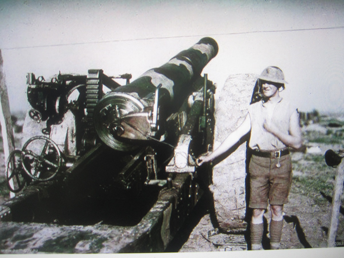
The 1916 Vickers 8” Howitzer.
The United Kingdom entered WWI with its traditional lack of preparedness. Defence funds had been lavished on the Royal Navy to maintain the ‘Two Fleet’ policy, whereby Britain could deter attack by having a fleet more effective than the combined force of the world’s next two largest navies. The Kaiser wanted a fleet to rival his cousin Edward’s and later cousin Georges. The ensuing arms race drained the tax revenue leaving little in the budget for the army. The army was still equipping itself for mobile warfare after the needs of the Boar War and had a good supply of very mobile light field artillery, very few machine guns and an inadequate inventory of mobile heavy guns.
The failure of the Schlieffen plan to take Paris and the channel ports, against stubborn resistance, resulted in the continuous trenches from the channel to Switzerland. German policy was to build a strong defensible line and hold their gains. To this end they employed their normal thorough approach and by 1916 had fortified their numerous layers of trenches with deep concrete dugouts to give protection and a modicum of comfort to their frontline forces. They had also retreated to gain the tactical advantage of high ground where applicable. France and Britain, understandably had an offensive policy and didn’t build strong or comfortable trenches. Break through, then attack with cavalry thinking dominated strategy and tactics . Germany began attacking the Verdun Forts in late February 1916. General Falkenhayns stated objective being to “Bleed France Dry”and this they were close to achieving. The British were rushed into the long planned attack between Serre and Montauban, nine miles of front, to relieve pressure on the French. The French were to attack on the British right flank, though this was scaled down due to the huge losses at Verdun. The British attack plus the diversionary attack at Gommecourt were together, known as the Big Push. This being the first major attack by Field Marshal Kitchener’s Volunteer Army, morale was at peak, despite the average three months the new battalions had spent rotating through front line duty; the sector was a quiet one.
In August 1915 the Vickers 8” Howitzer was approved however an order for 50 was not placed until March 1916 and delivery began in July 1916. The Howitzer fired a 91kg, 8” diameter shell a maximum distance of 11,000 yards, it’s trajectory was high and therefore it gave plunging fire, ideal, with appropriate fusing, to penetrate deep dugouts. There were a few makeshift large calibre pieces in operation in June 1916 but these were thinly spread along the nine mile front, they were mainly stopgap weapons made by modifying old naval guns. The Royal Field Artillery staple weapon was the quick firing 18 pounder, firing a projectile weighing 8kg with a range of 6500 yards.
1918 Vickers 8″ Howitzer.
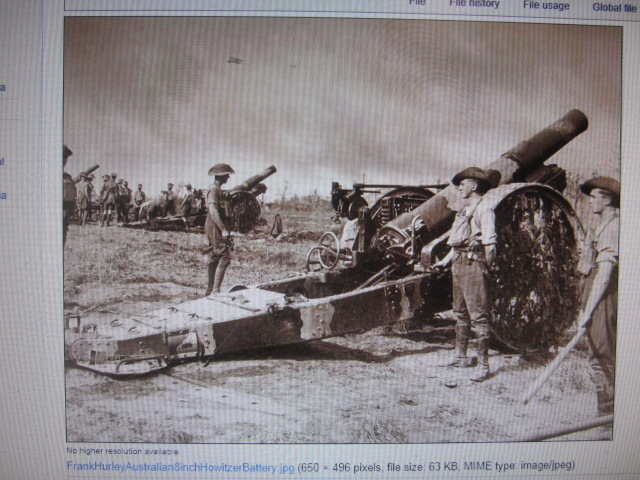
Australian 8″ Howitzer battery
The attack was scheduled for the morning of July 1st and preliminary bombardment began one week earlier. Huge stocks of shrapnel and high explosive shell for the 18 pounders were in place, far fewer heavy shells were available. The plan was that the new spigot mortar, firing a basketball sized high explosive projectile, together with the 18 pounders would break up the fields of barbed wire and kill sufficient front line defenders to make the 100yard to one mile crossing of no-mans-land, without cover, survivable. Results on the wire were patchy and on the dugouts feeble at best. Only British forces adjacent to the French sector, with a high density of artillery, had a real chance success, near the villages of Fricourt and Montauban
The Attack began at 7.20am on that clearing misty July morning, with the explosion of a large mine under the German front line at Hawthorn ridge near Beaumont Hamel, followed by a series of similar mines at 7.30am. Orders to the first waves of infantrymen were to advance at walking pace with rifles at high port and occupy the German frontline. Later waves were to attack the second and third lines to facilitate a cavalry breakthrough. These orders ignored reports all week, from trench raiders, saying that the dugouts and occupants were intact and only the odd lookouts were killed by the bombardment. Also that the majority of the wire was undamaged.
In the first two hours of the attack, most of the 19,000 attackers who died on the first day were dead, or lying mortally wounded, without reaching the German lines. Likewise a further 40,000 casualties had occurred and the trenches were blocked by walking wounded and dead men. The storm of machine gunfire and precisely zeroed German shell fire, cut down attacking companies and battalions in rows that represented the waves leaving the trenches. The Battle of the Somme, as it was later known was doomed on the first day, the squadrons of lancers and hussars remained behind the British trenches unable to take part in the planned big break through. 1st July 1916 had the highest number of casualties for any attack by British forces. By comparison on the first day of the landings in Normandy in 1944, there were 4,500 total allied forces killed.
The failure of this attack is attributed by most historians to the lack of sufficient heavy artillery in the preliminary bombardment like the Vickers 8 inch howitzer,. Had the 50 guns been ordered three months earlier, who knows what lives would have been saved on both sides by shortening the war.
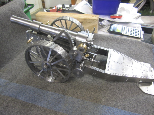
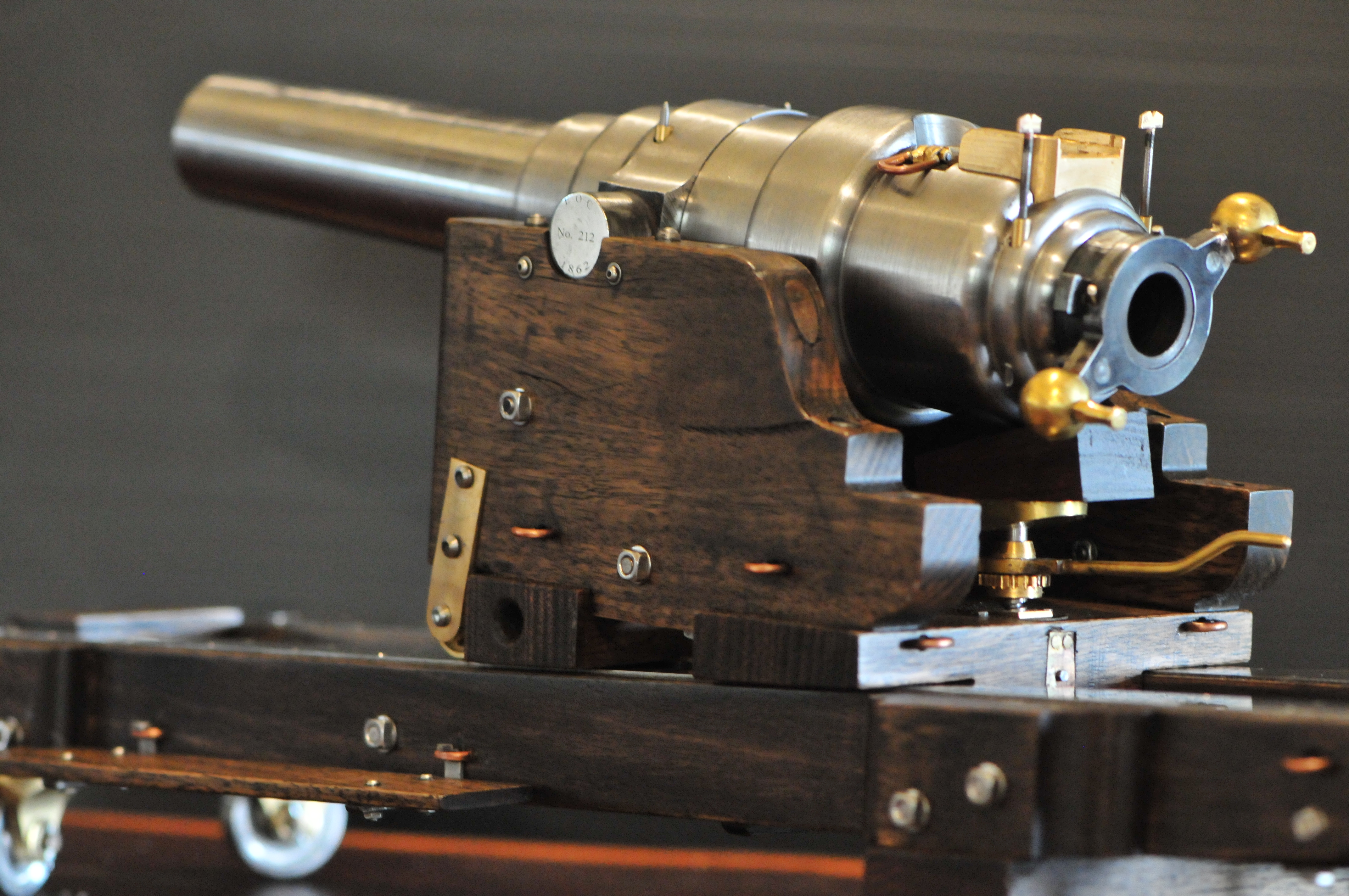
- The almost complete model. OAL 450mm
THE MODEL
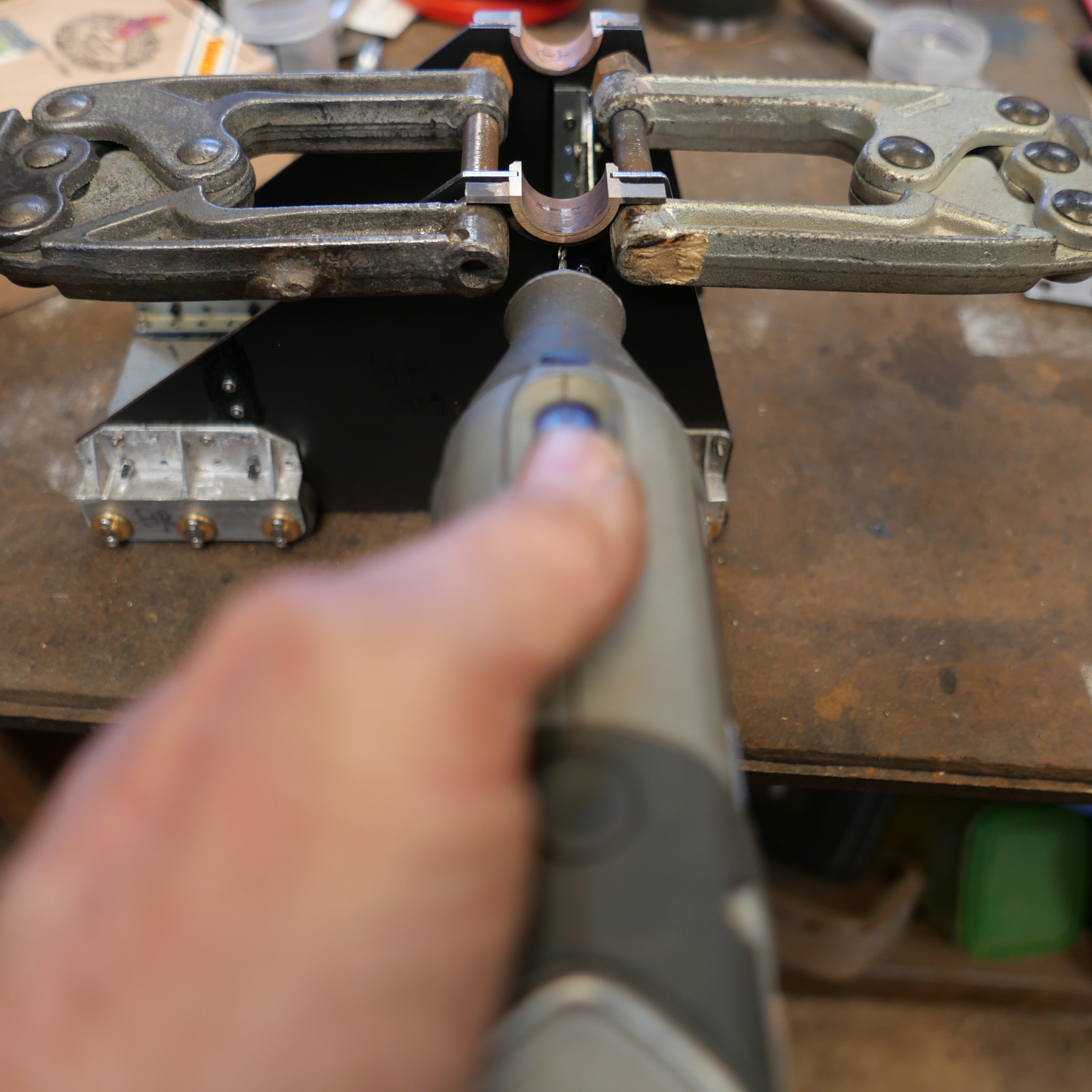
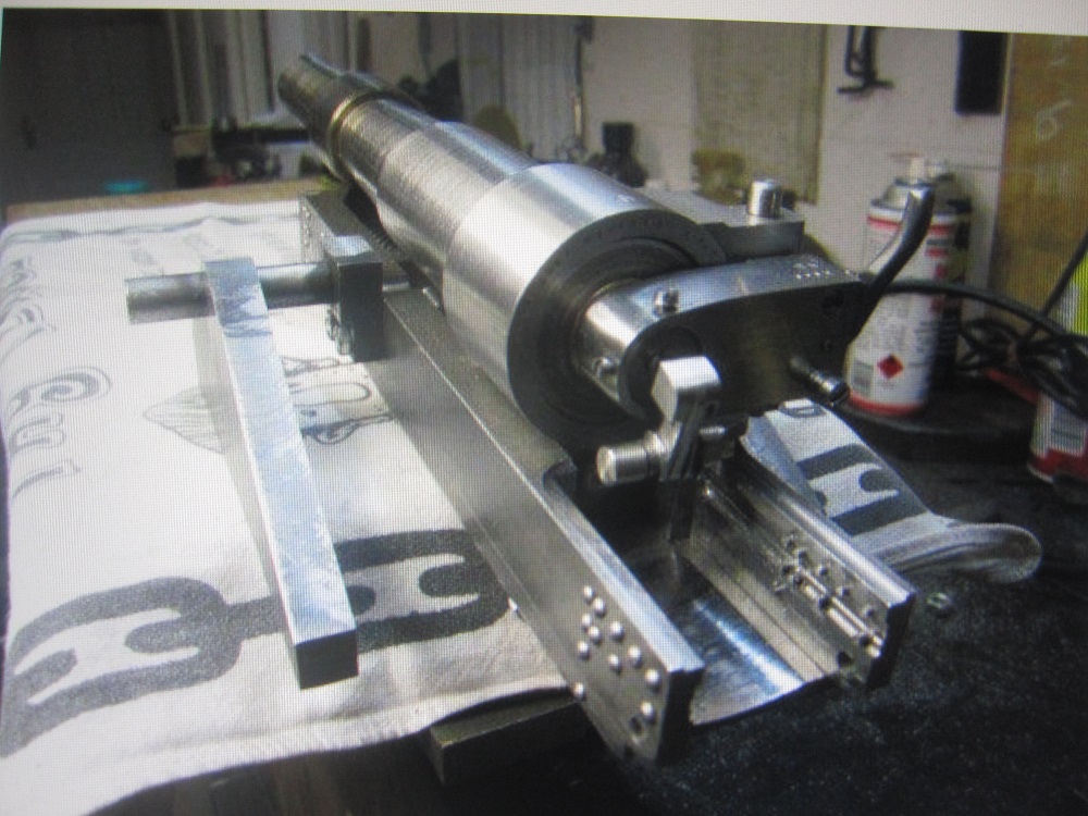
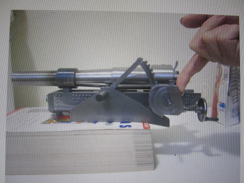
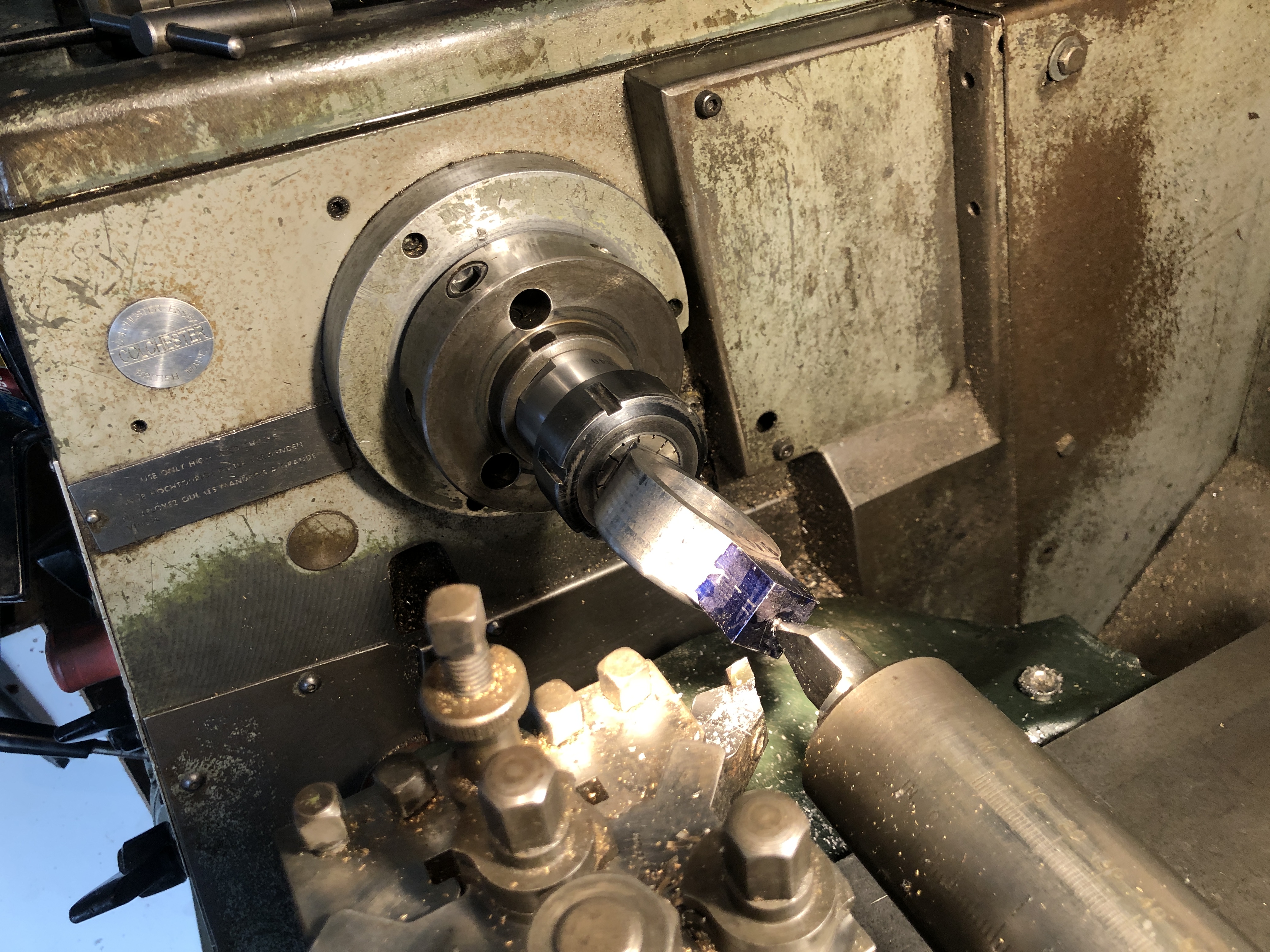
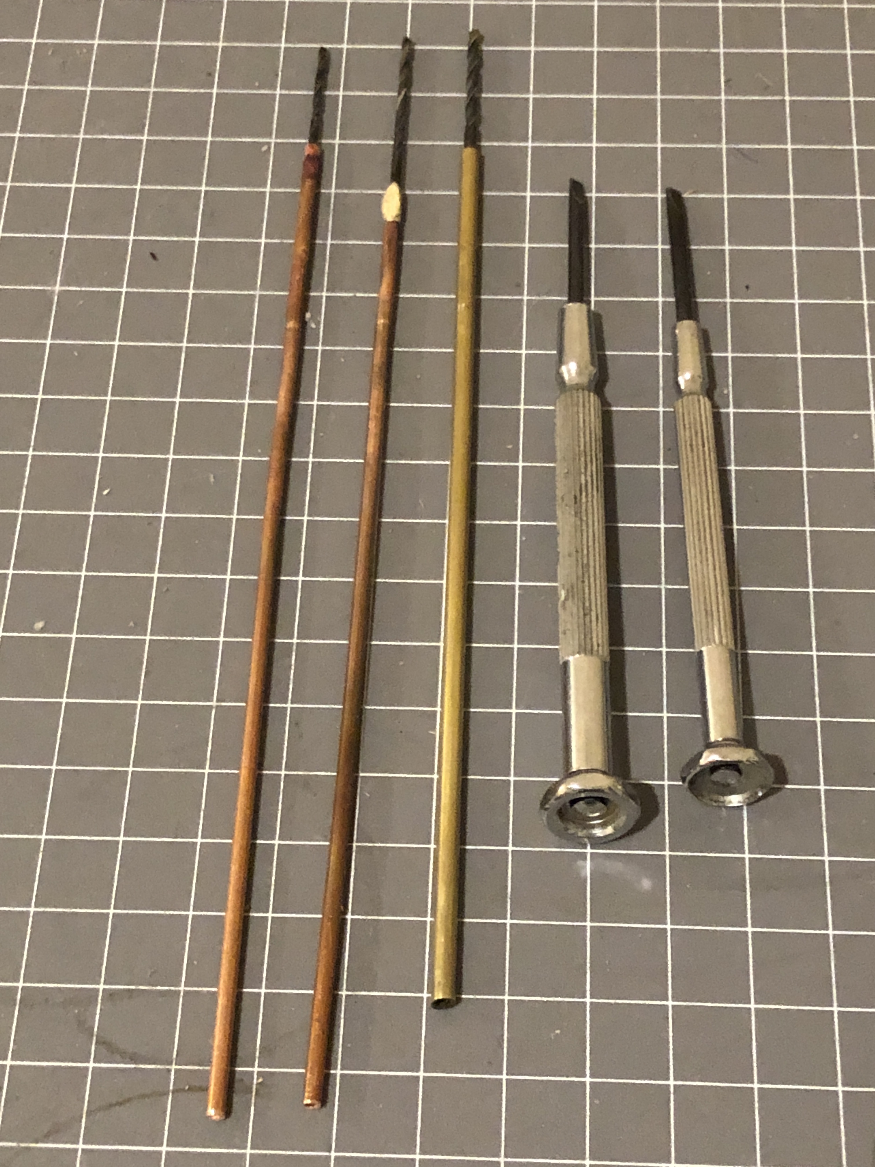
The model was built to a firm budget for an individual in the U.K. The agreement was to build a fair representation of the Vickers 1916 8” Howitzer with no more than 250 rivets. The final number of rivets was over 500. Construction took just under 900 hours and only the nuts, bolts, two hand wheels and main gears were purchased. The model was not capable of firing having a rifled liner in the barrel (like the original) that did not extend to the breech. The breech was a four segment rotating thread type operated by moving a lever through an arc of 45 degrees. The upper chassis had elevation and traverse mechanisms and the barrel had a spring loaded recoil ability. Rifling the barrel liner was a problem. Testing the single cutter broach showed location and spacing problems. Multi cutter broaching exceeded the pushing power available, even on aluminium. These techniques work well on large production machinery cutting four or five groove barrels. This barrel needed thirty plus grooves. Having seen a toolmaker friends EDM set up I had the idea of making a copper male button to be passed spirally down a steel liner cutting electrically in the electrolyte. It worked splendidly first go and took about 20minutes. (editor’s note… “wow”)
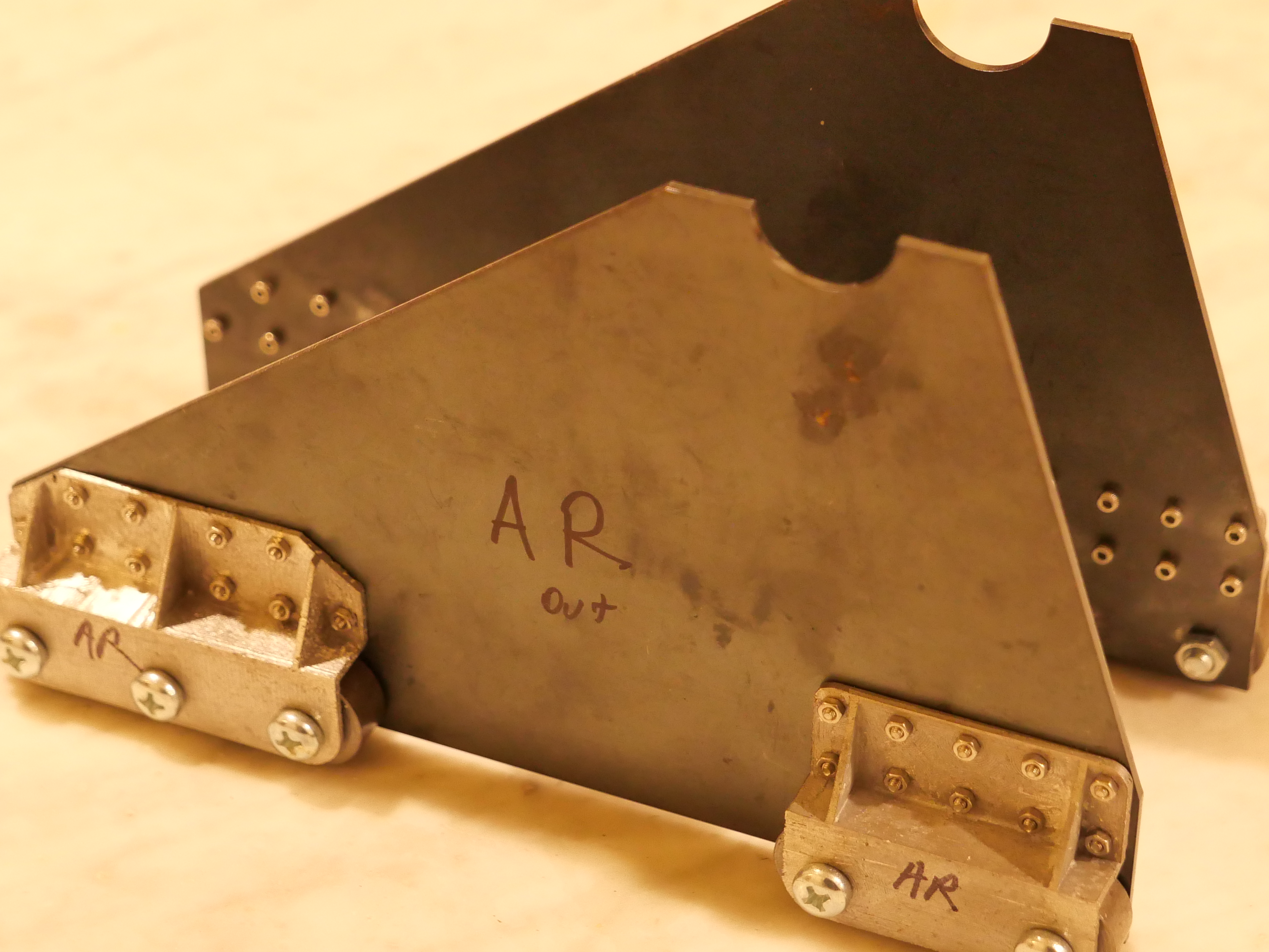
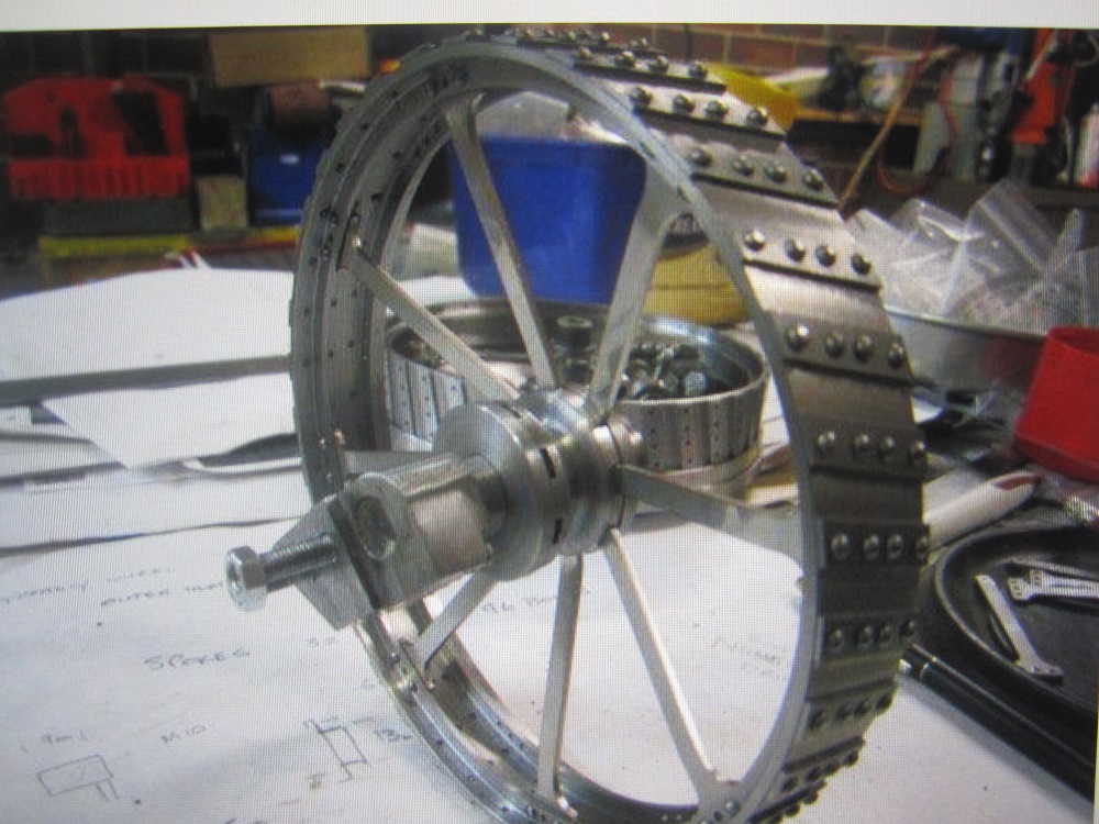
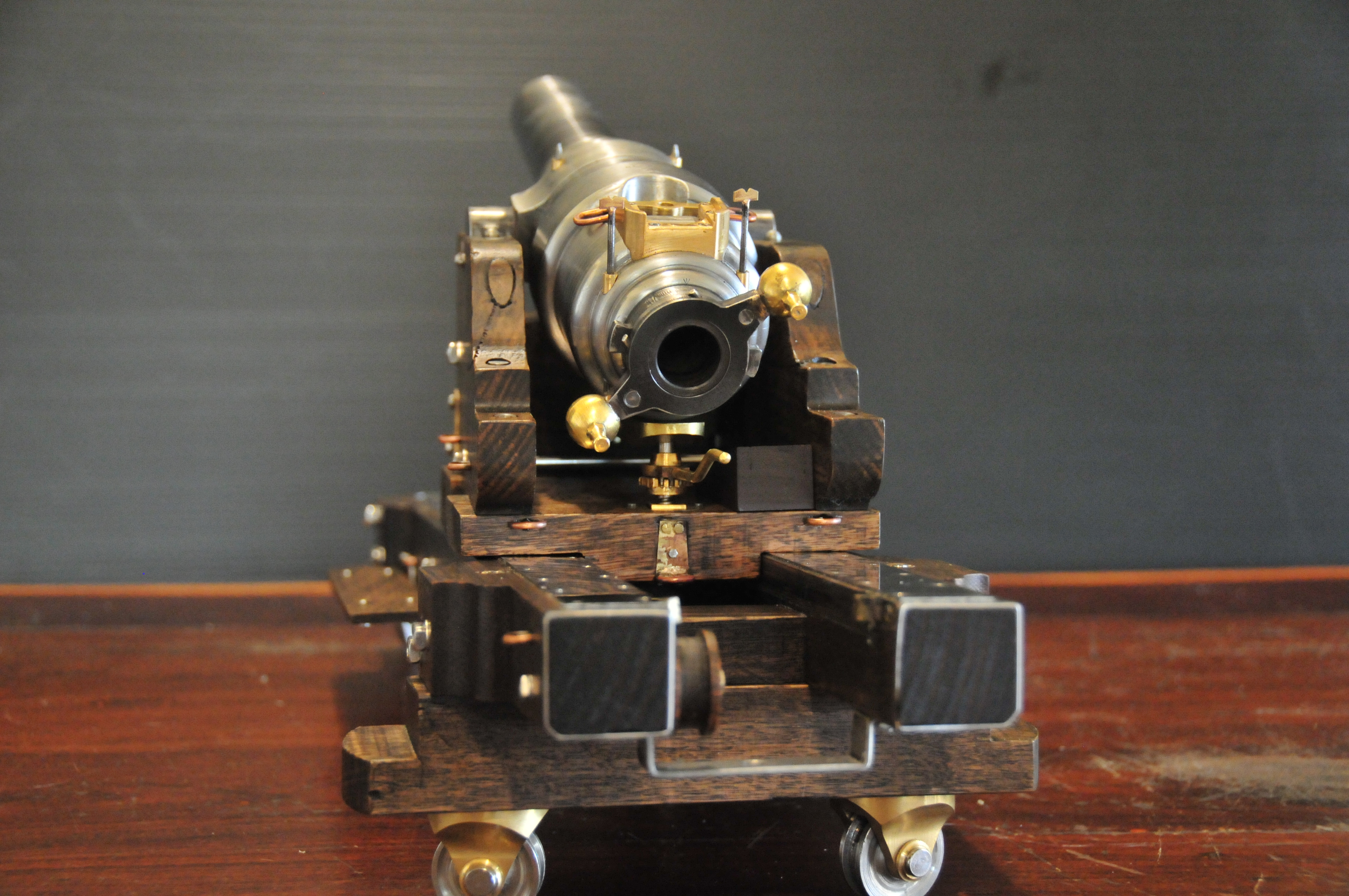
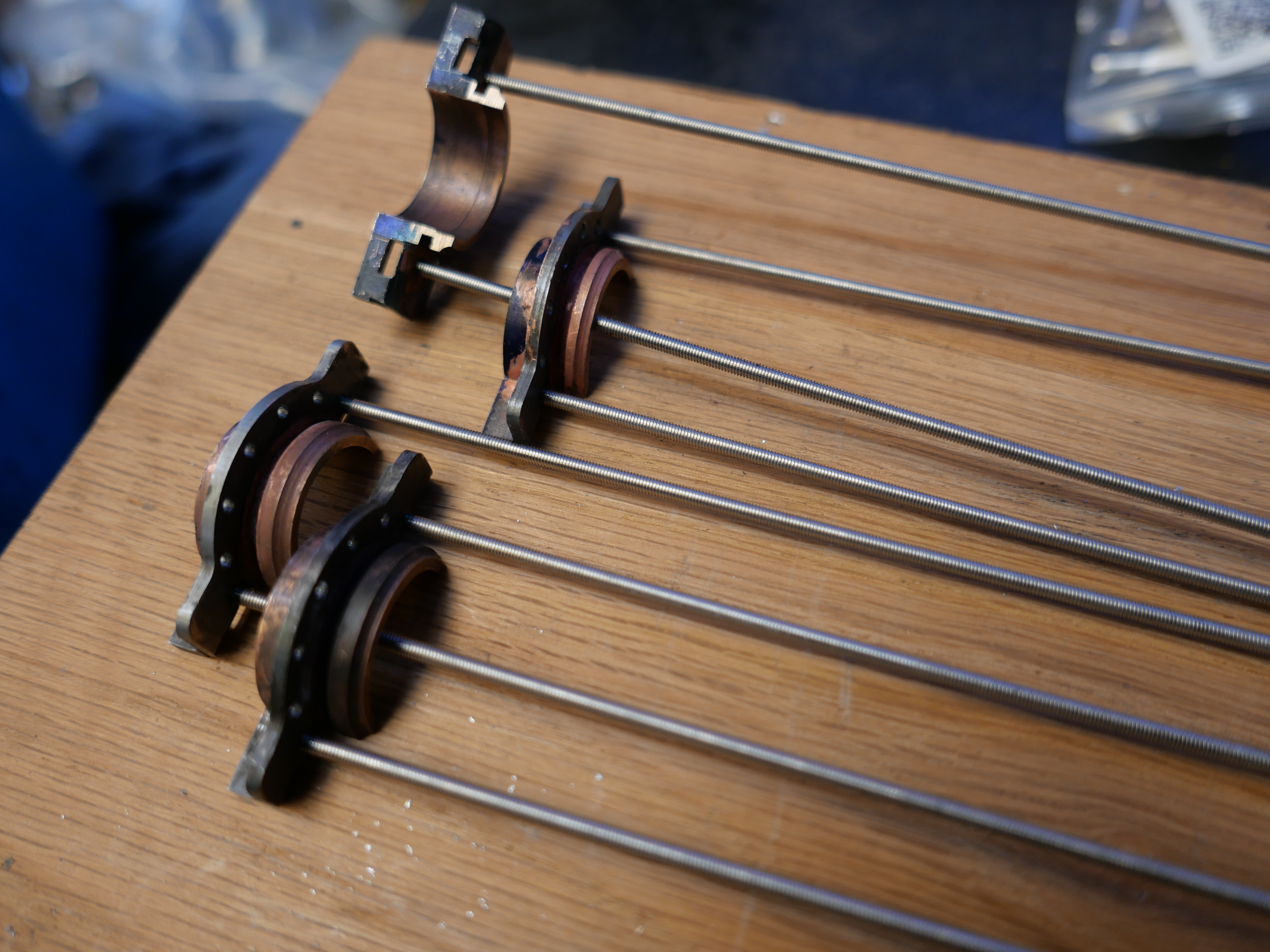
The wheels were approximately 7” in diameter, classic traction engine types, with the rims machined from thick walled steel pipe and the spokes laser cut. The chassis, upper and lower, were cut from solid plate rather than fabricated, this was due to budget constraints. The scale of the model was 11:1 and resulted in dimensions of : bore 19mm, overall length 450mm.
There were no engineering drawings used for the build only the line drawing shown and lots of web photographs, all of these were of later marks of the 8 inch and some were complicated by being shown in reverse from glass plates. The gun was still in service in 1939 though by then it had pneumatic tyres and lots of refinements.
Robert Irving 2019.

The drawing which was used to make the model..

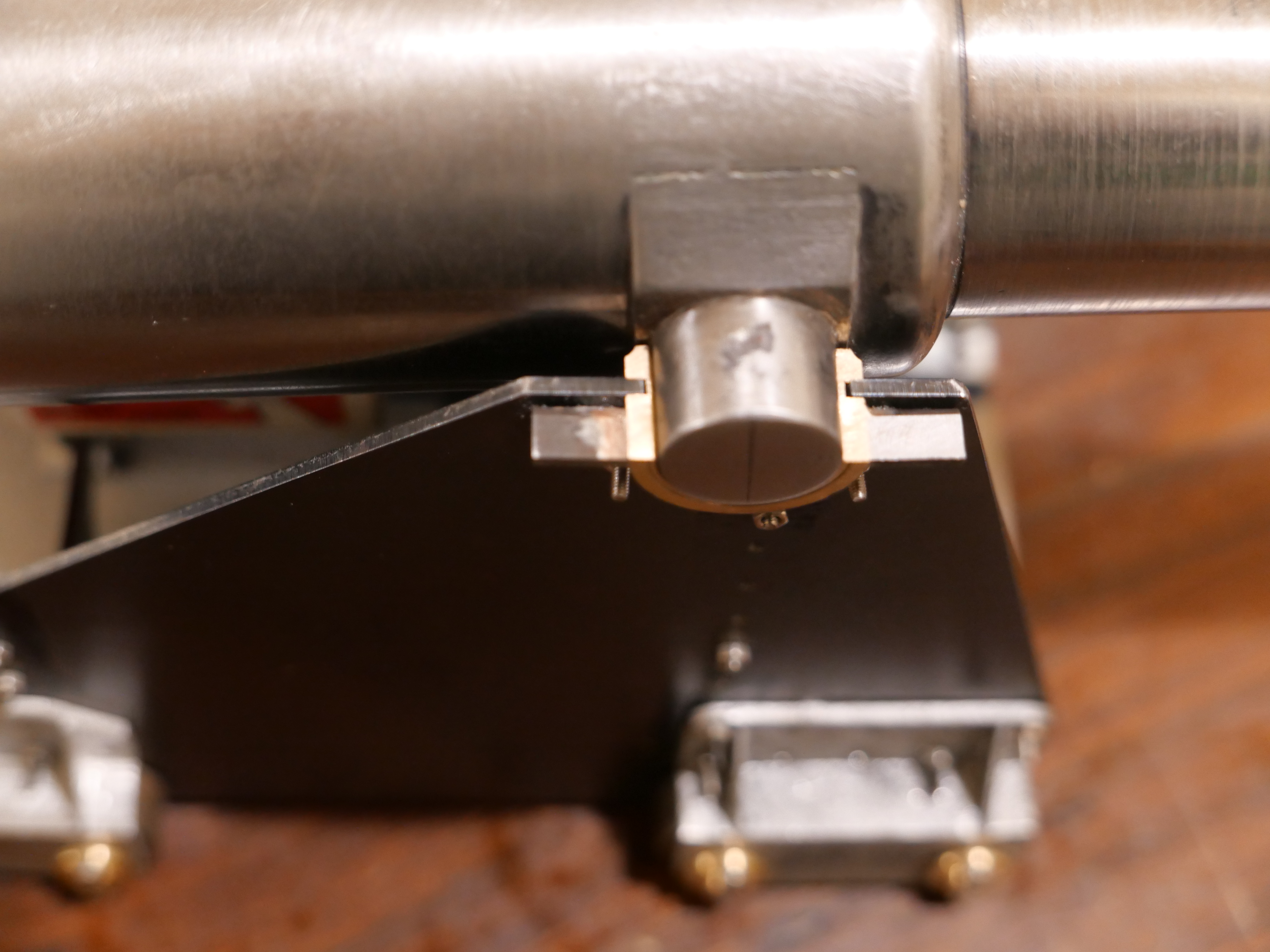
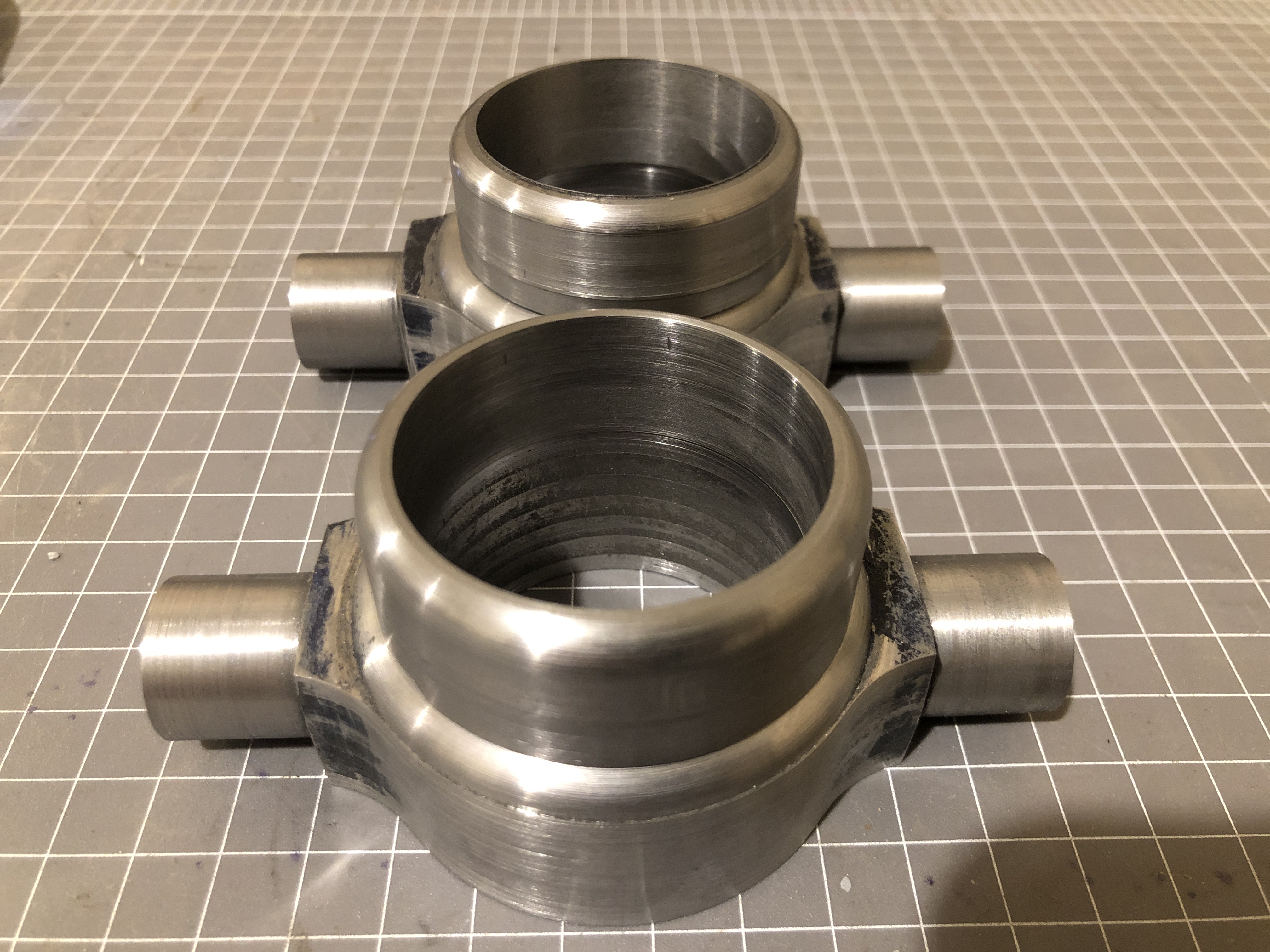
Boring the barrel

Note the rifling.

Wide track

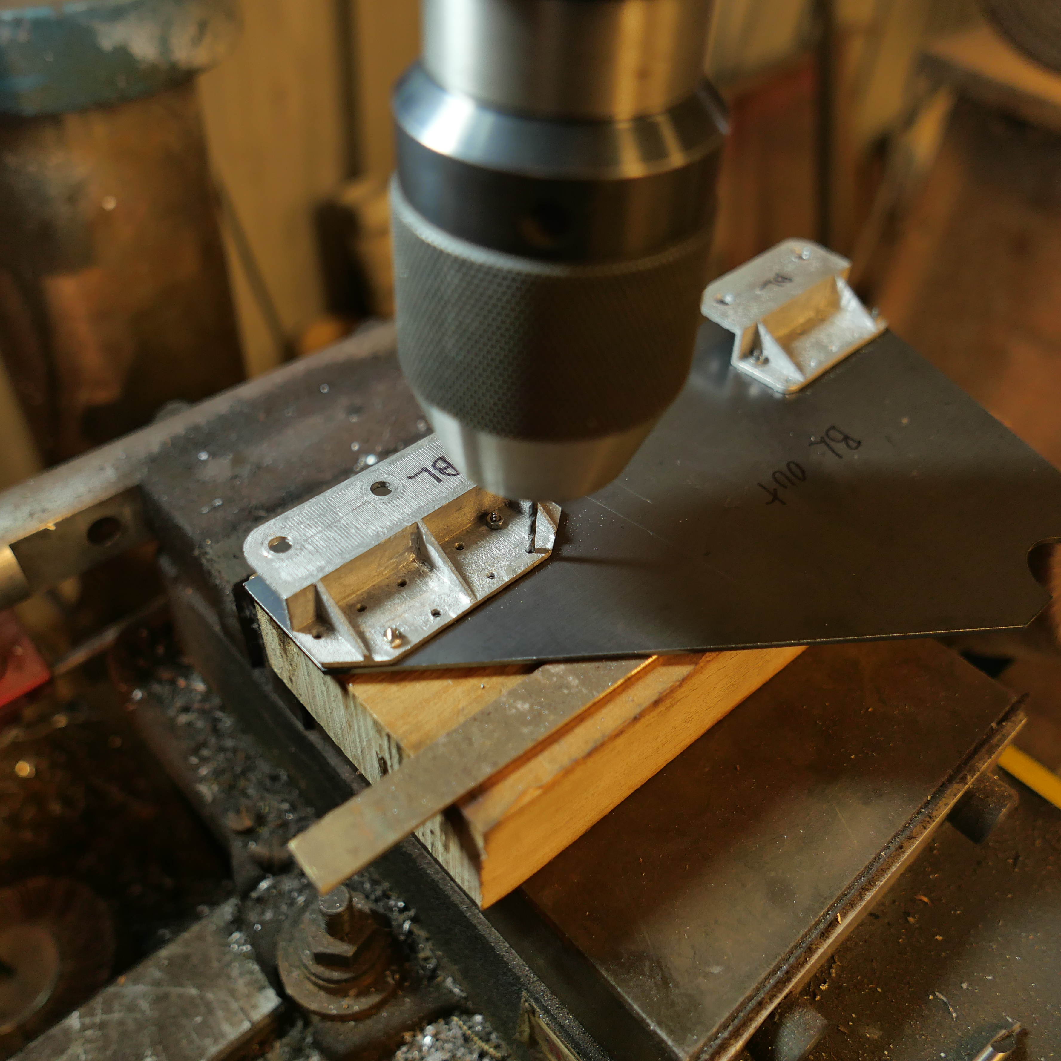
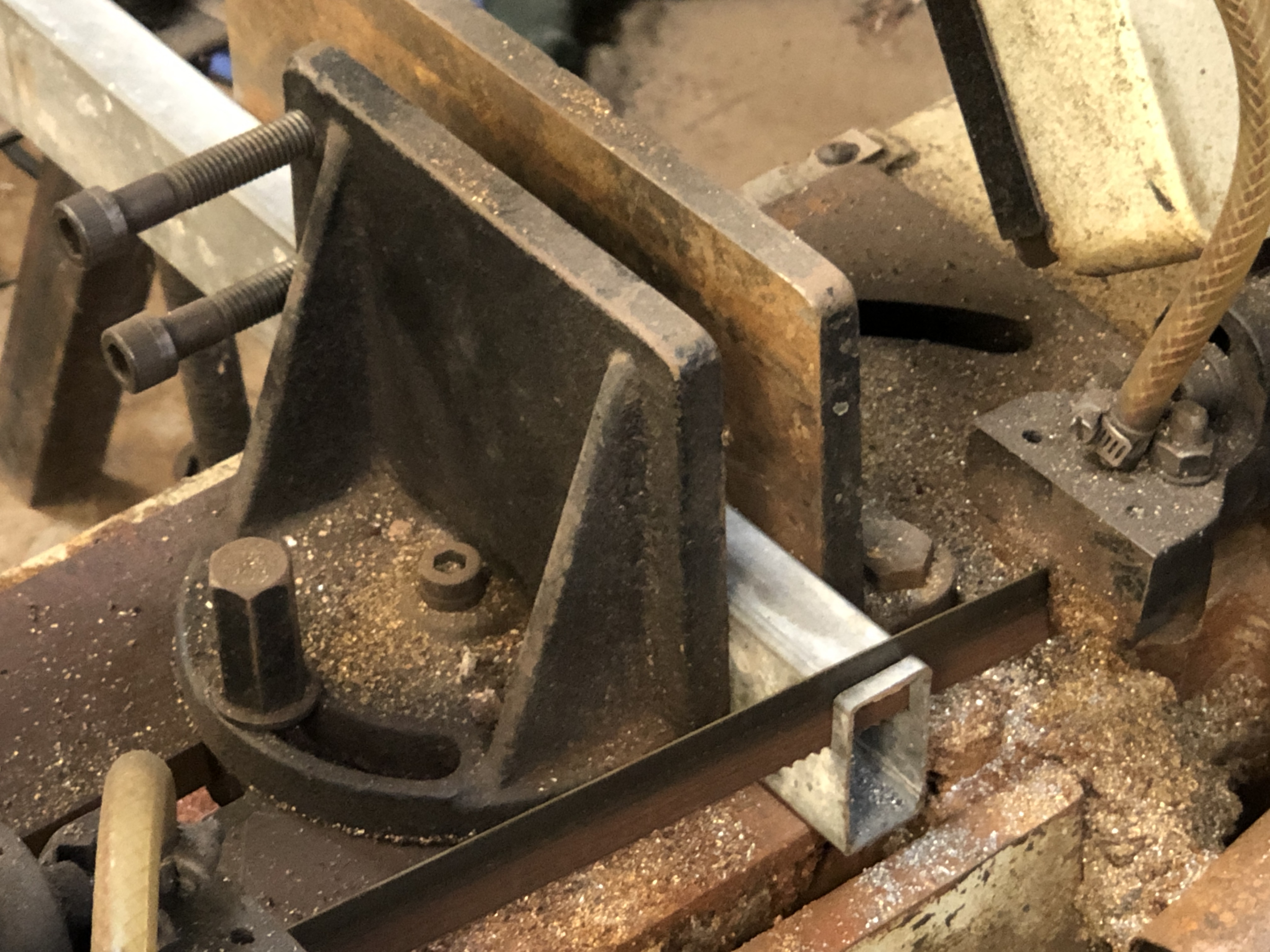
Wheel hub drilling jig

The spokes were laser cut
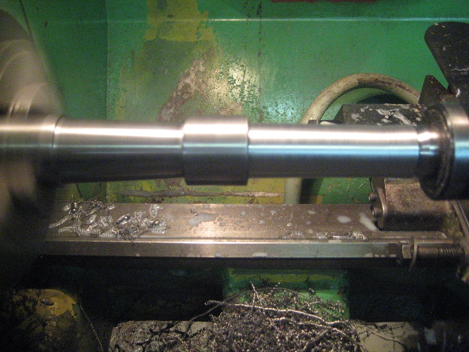
Turning the barrel

In recoil

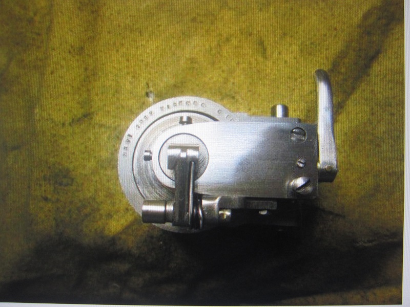
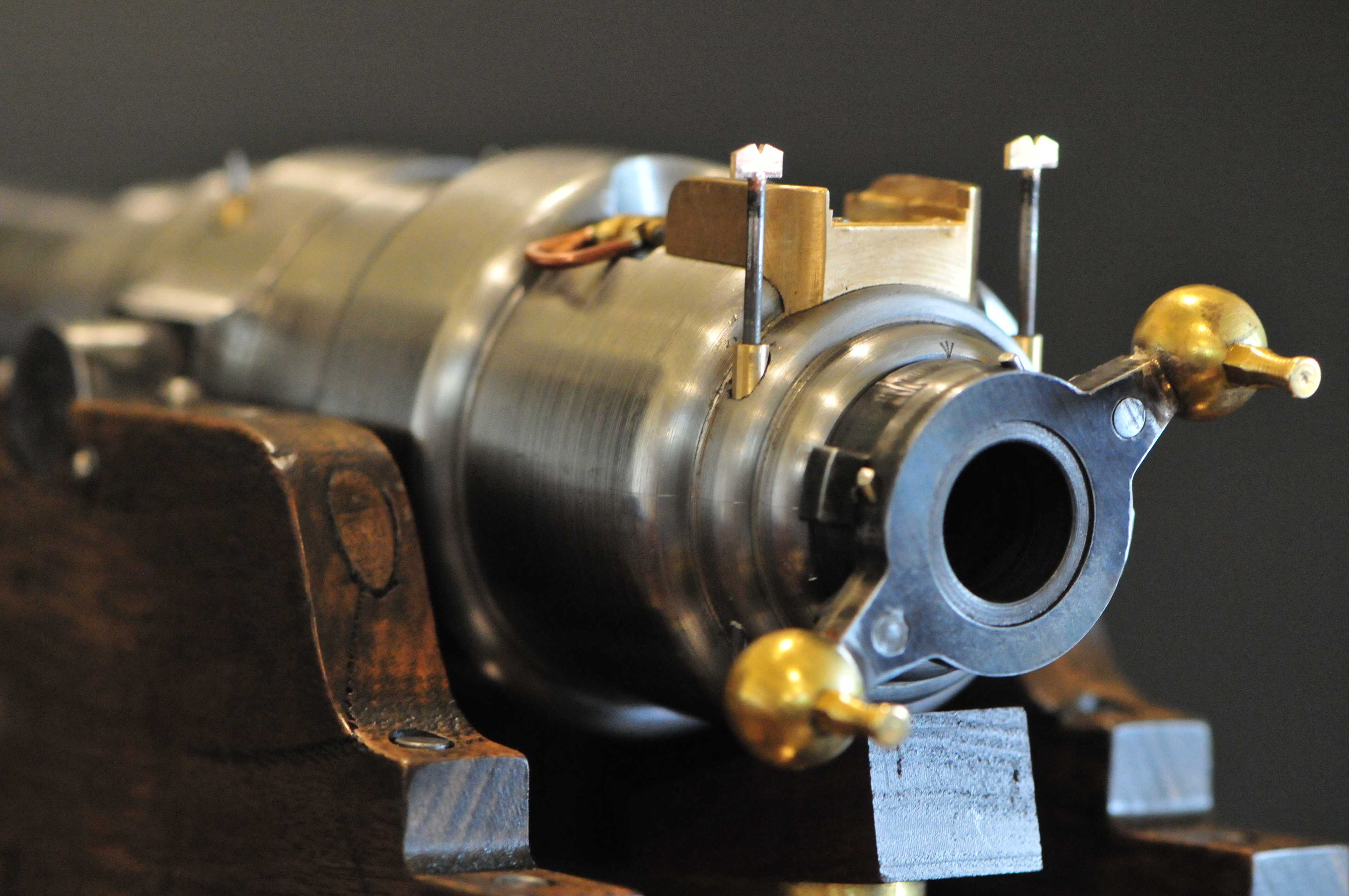
Breech
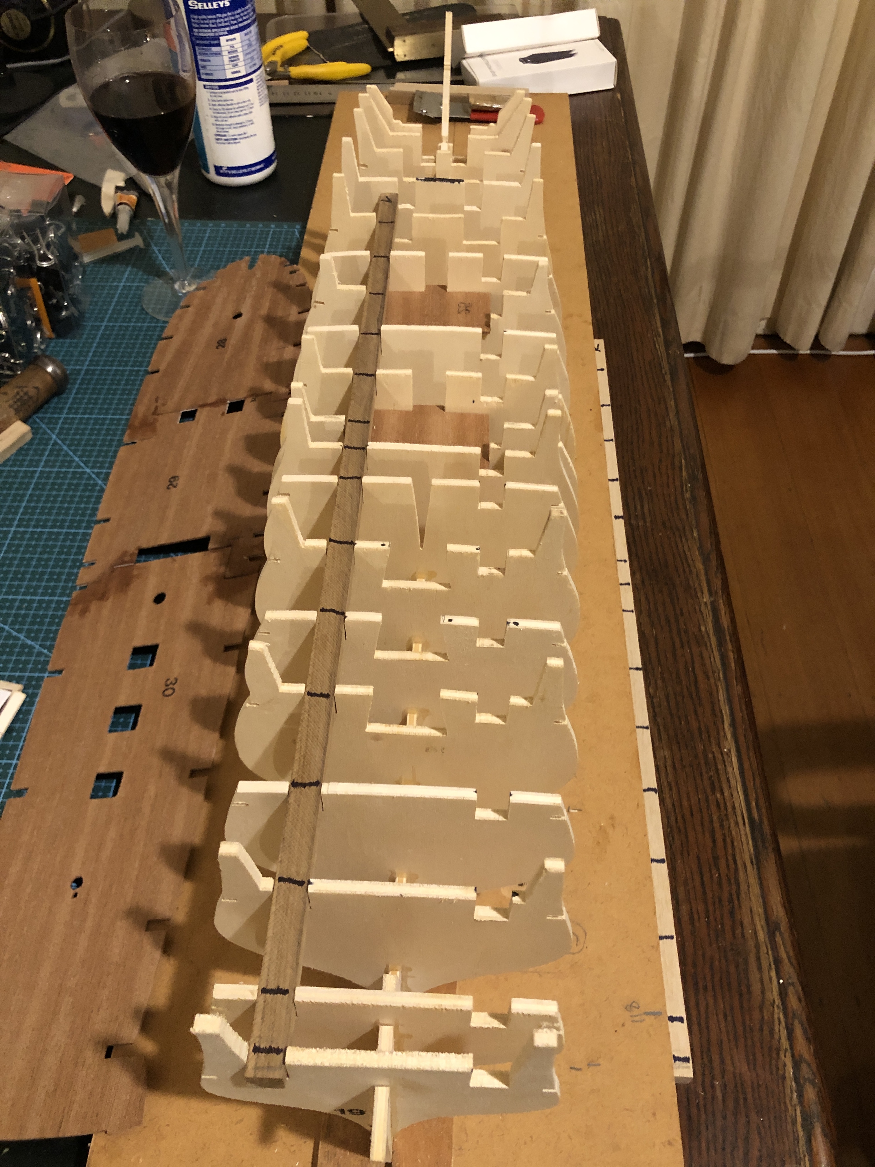
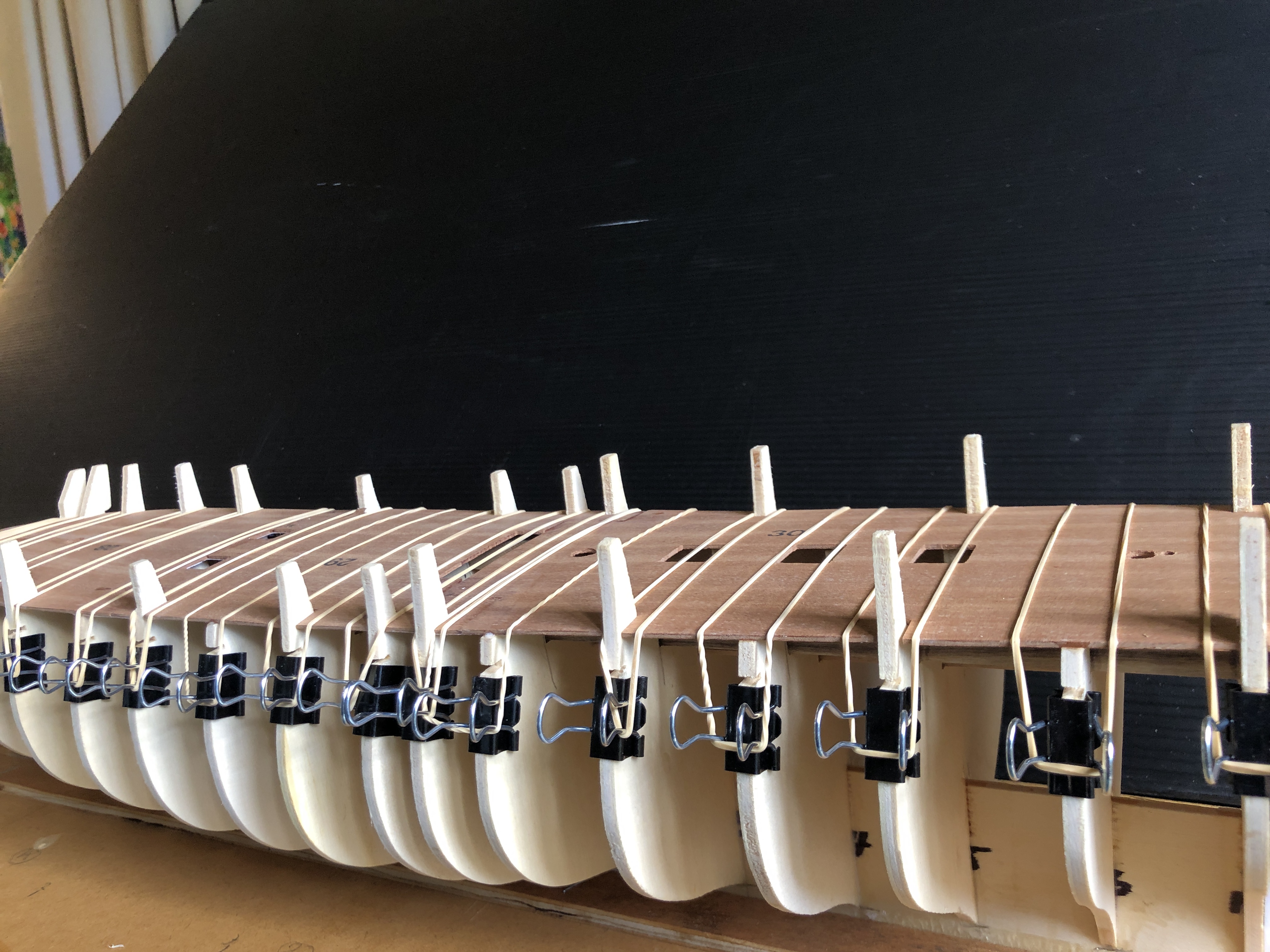
Early assembly


Completed model
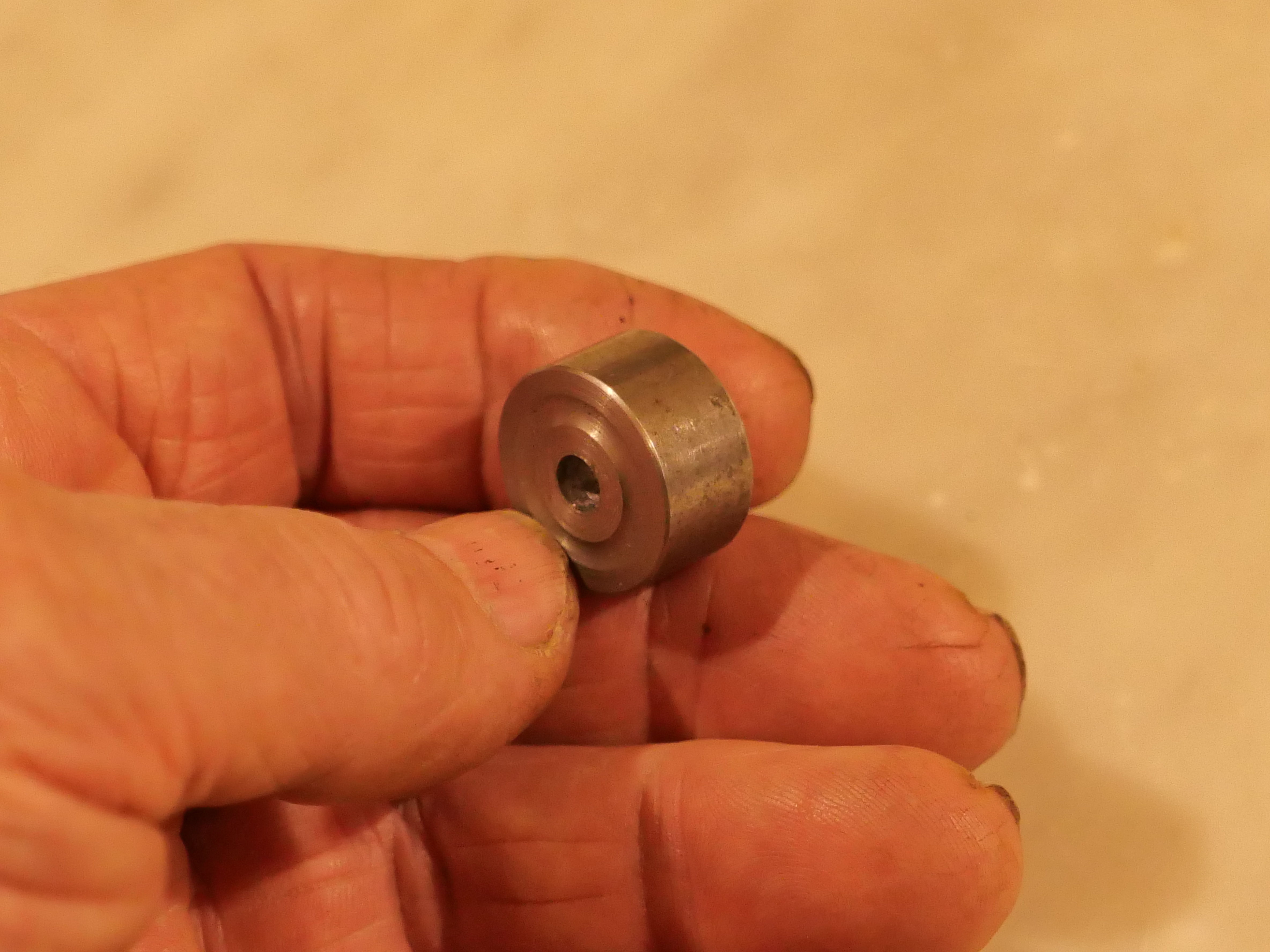
Hand for scale

The rims
So, again, thanks to Robert for the photos and historical context of this superb model.


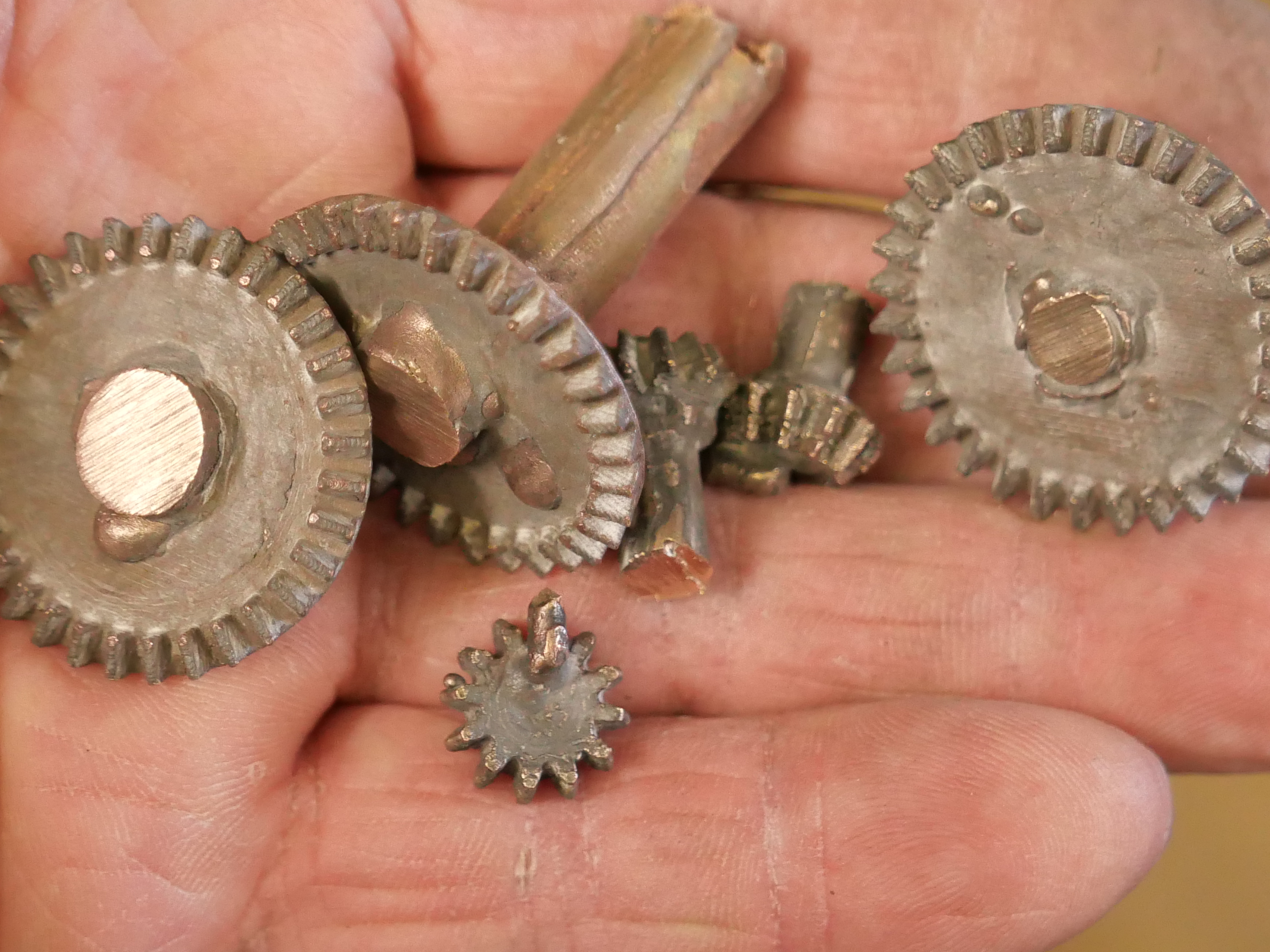


 Tidied the parts with a file and belt sander.