johnsmachines

machines which I have made, am making, or intend to make, and some other stuff. If you find this site interesting, please leave a comment. I read every comment and respond to most. n.b. There is a list of my first 800 posts in my post of 17 June 2021, titled "800 Posts"

Tag: Fowler traction engine

Just for the Record

I am back. Looking at my photos over the past month or more, not much of interest to my regular readers. In fact, very little time spent in the workshop. I have been chauffeur for SWMBO, to and from hospital and medical appointments. Buying groceries. Cooking. Infrequent visits to GSMEE.

But, there was one day in Melbourne where I had a couple of spare hours, so I visited a cannon which has been on my bucket list for several years. Two cannons actually, but virtually identical.

High St, Northcote, Melbourne, (Victoria, Australia for my OS readers).

2 breech loader, rifled (of course), Armstrong cannons, of 1885 vintage.

And on the other side of High St is another gun of the same type. It is 5.88m/ 19′ long….

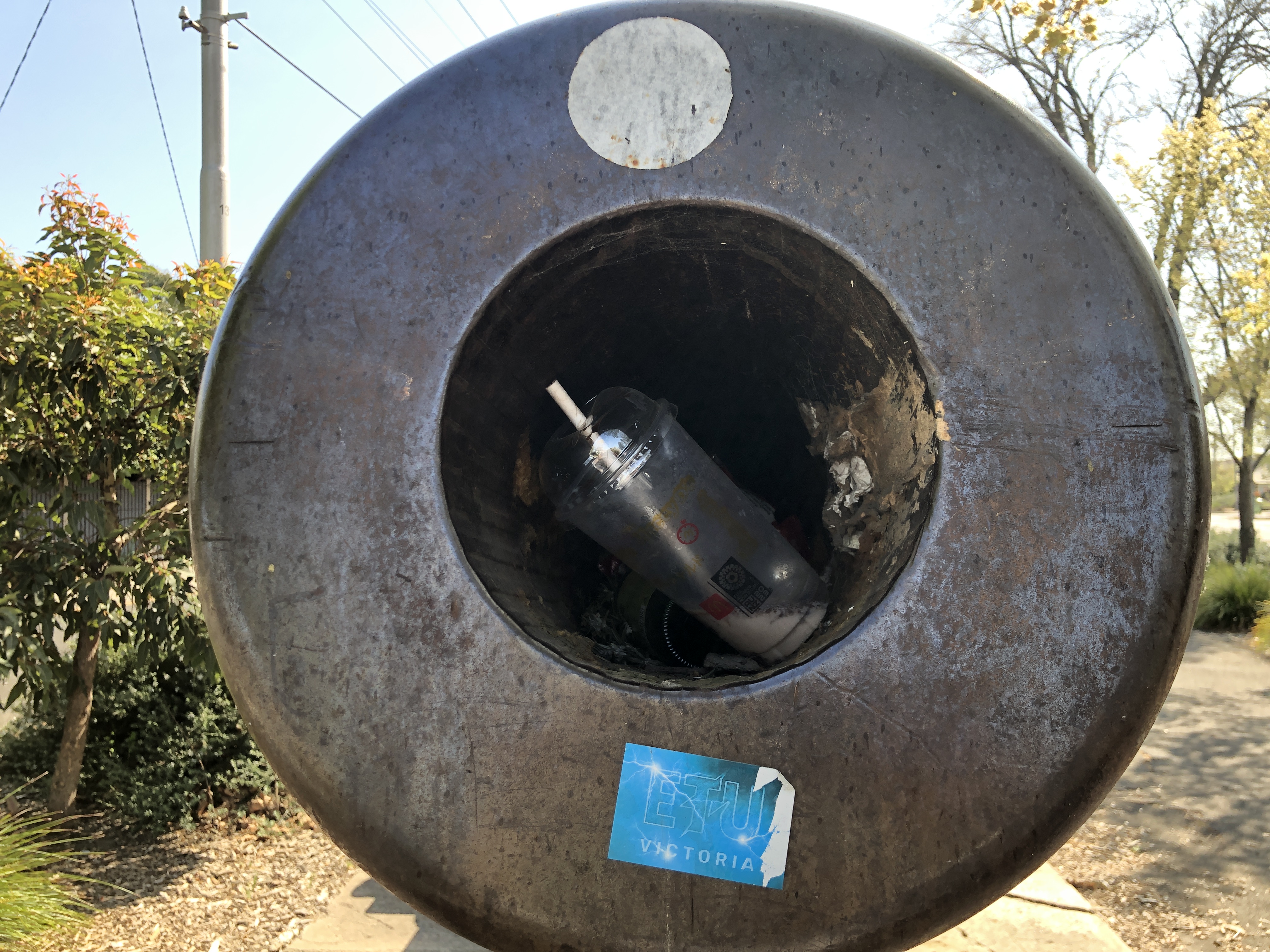
…and has an 8″ /203mm rifled bore. The bore serves as a rubbish bin for the local morons.

My artillery references categorise these guns as Armstrong pattern, breech loaders, of approximately 1885 vintage.

The Northcote guns have carriages which are naval types, and were possibly originally mounted on the gunboats HMVS Albert and HMVS Victoria. The barrels are the same as others which were originally mounted as garrison guns at South Channel Fort, Port Phillip Bay, Victoria. The Northcote barrel trunnions are covered, but said to be numbers 4312 and 4266. There is no barrel weight visible but these guns typically weighed just under 12 tons each. The slides are missing, but would have been pivoted at the front end.

The large breech mechanism is missing smaller removable components but is still impressive. The diameter of the breech is 918mm.

Said to have a range of 7500m. Projectile weight 95kg / 210lb

So. Will I model these guns? Without plans or good photographs of intact carriage and slide, probably not. But if I can locate such details……??

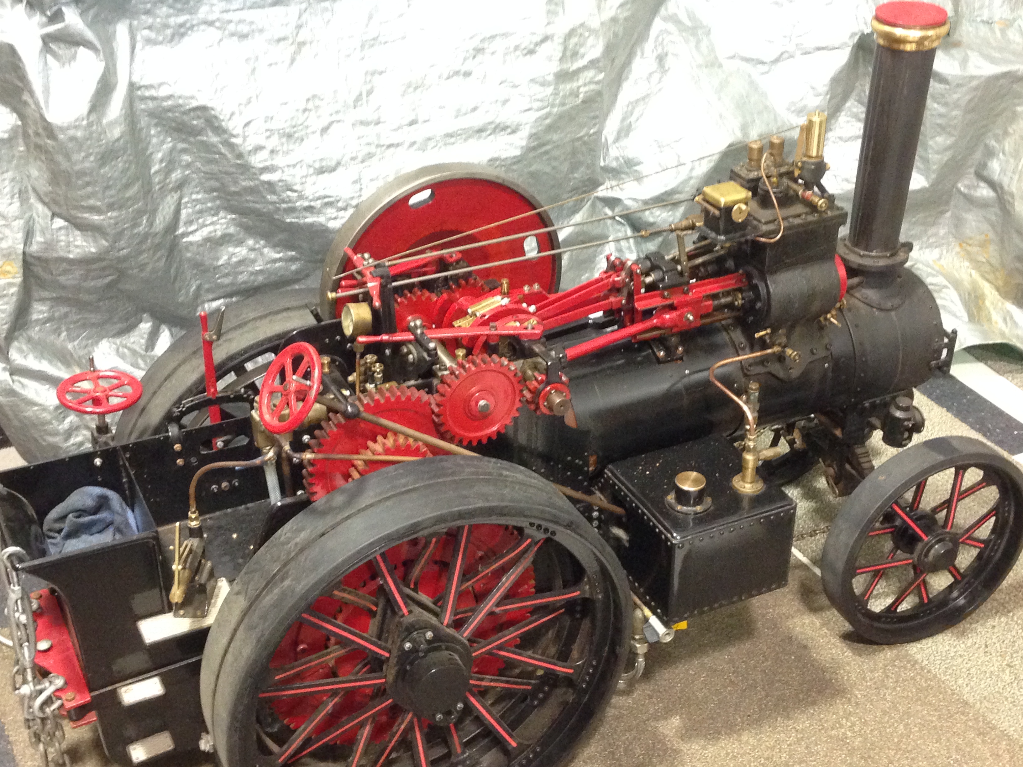
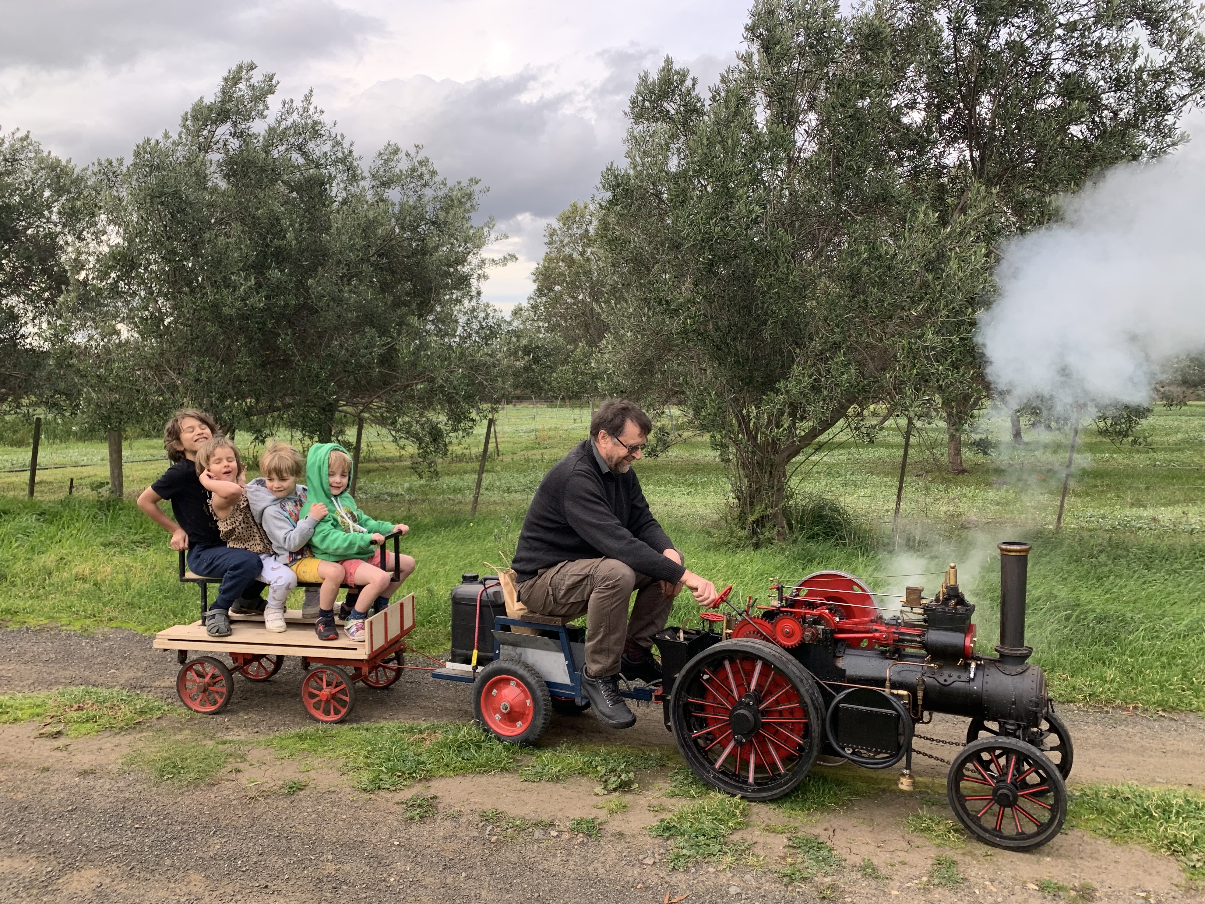
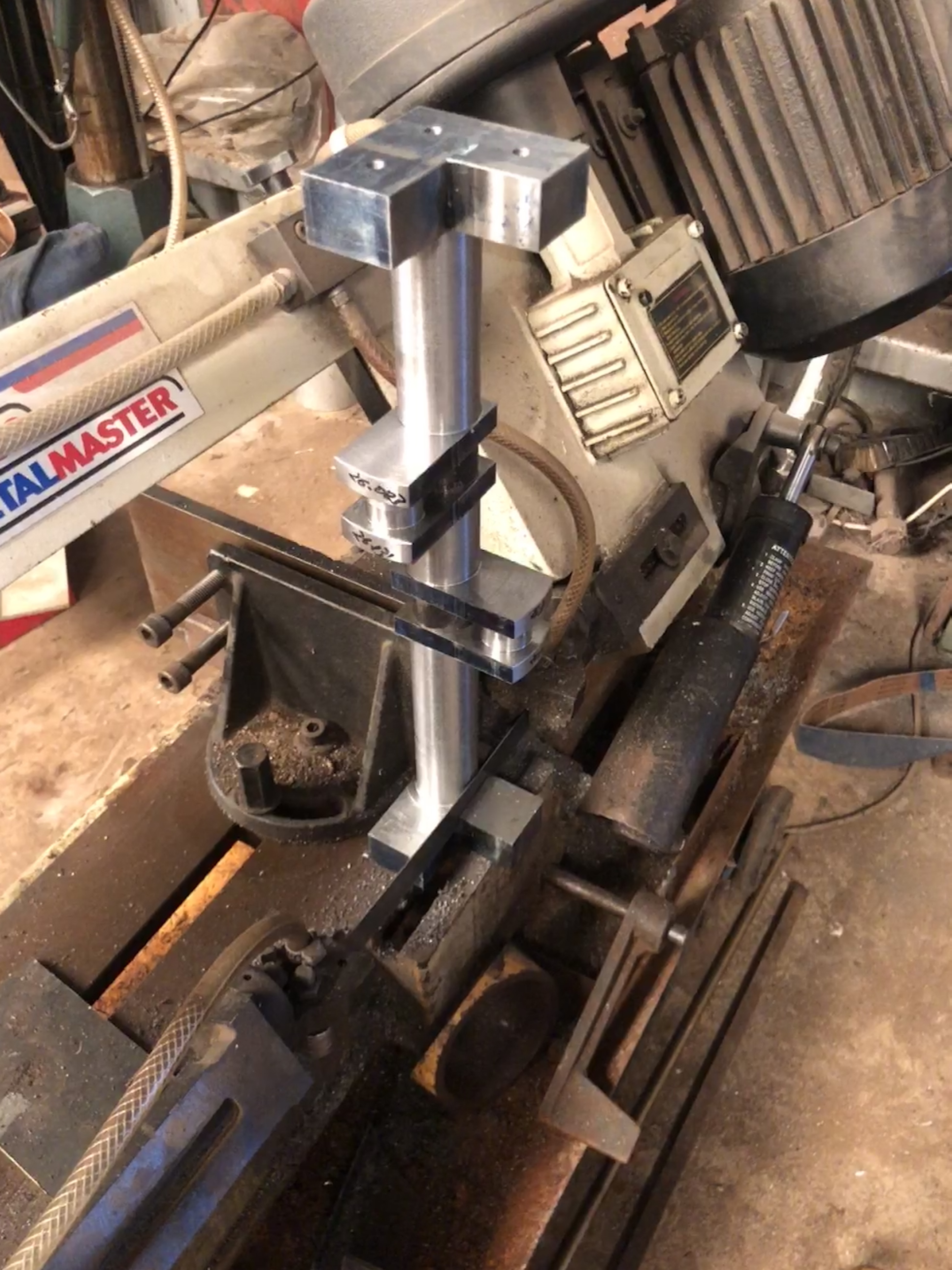
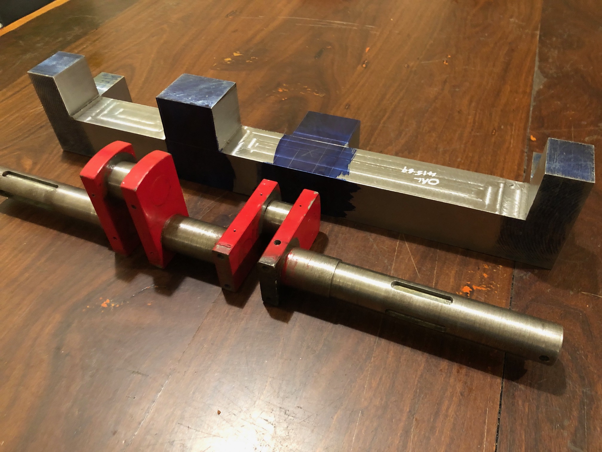
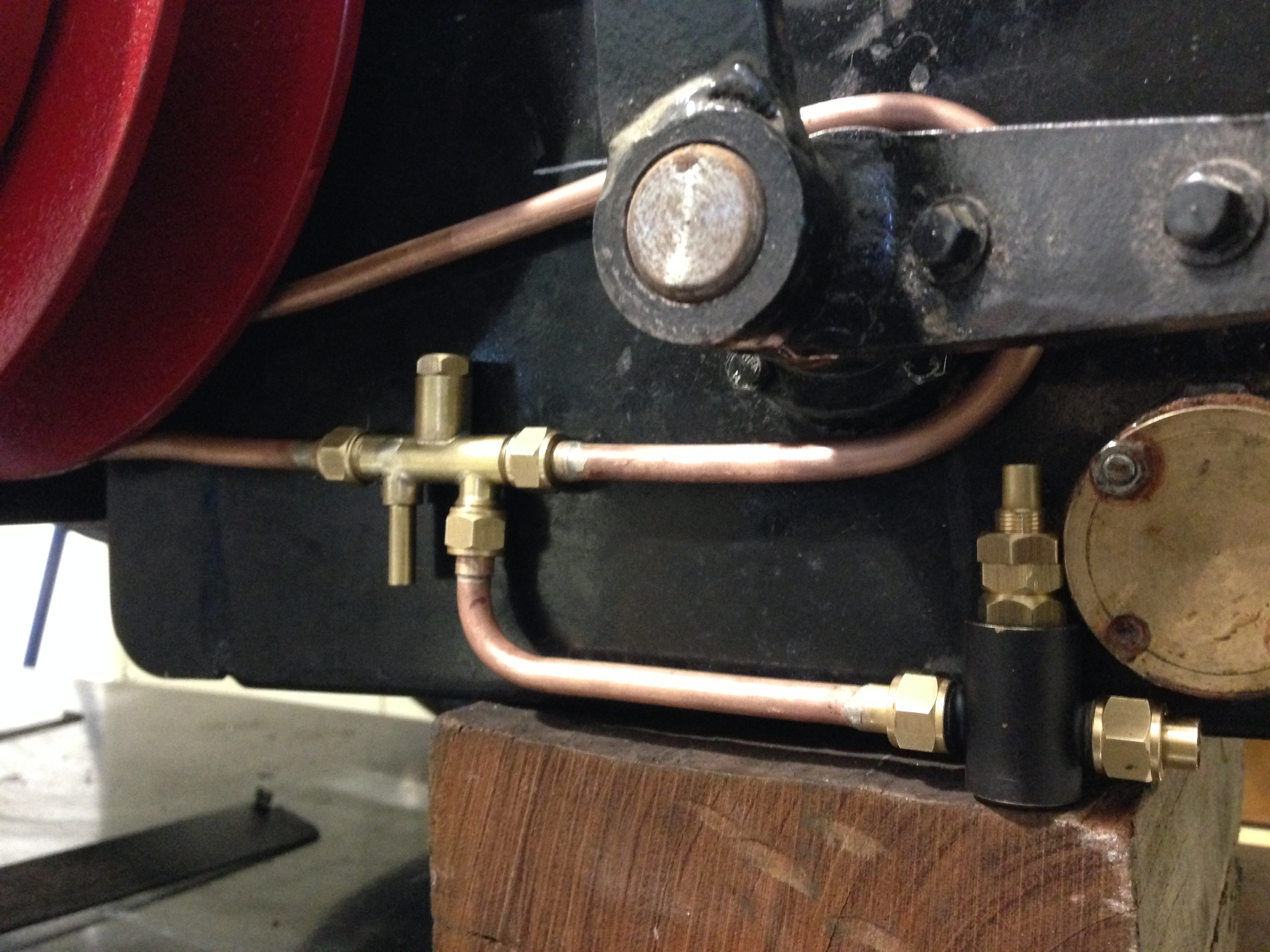
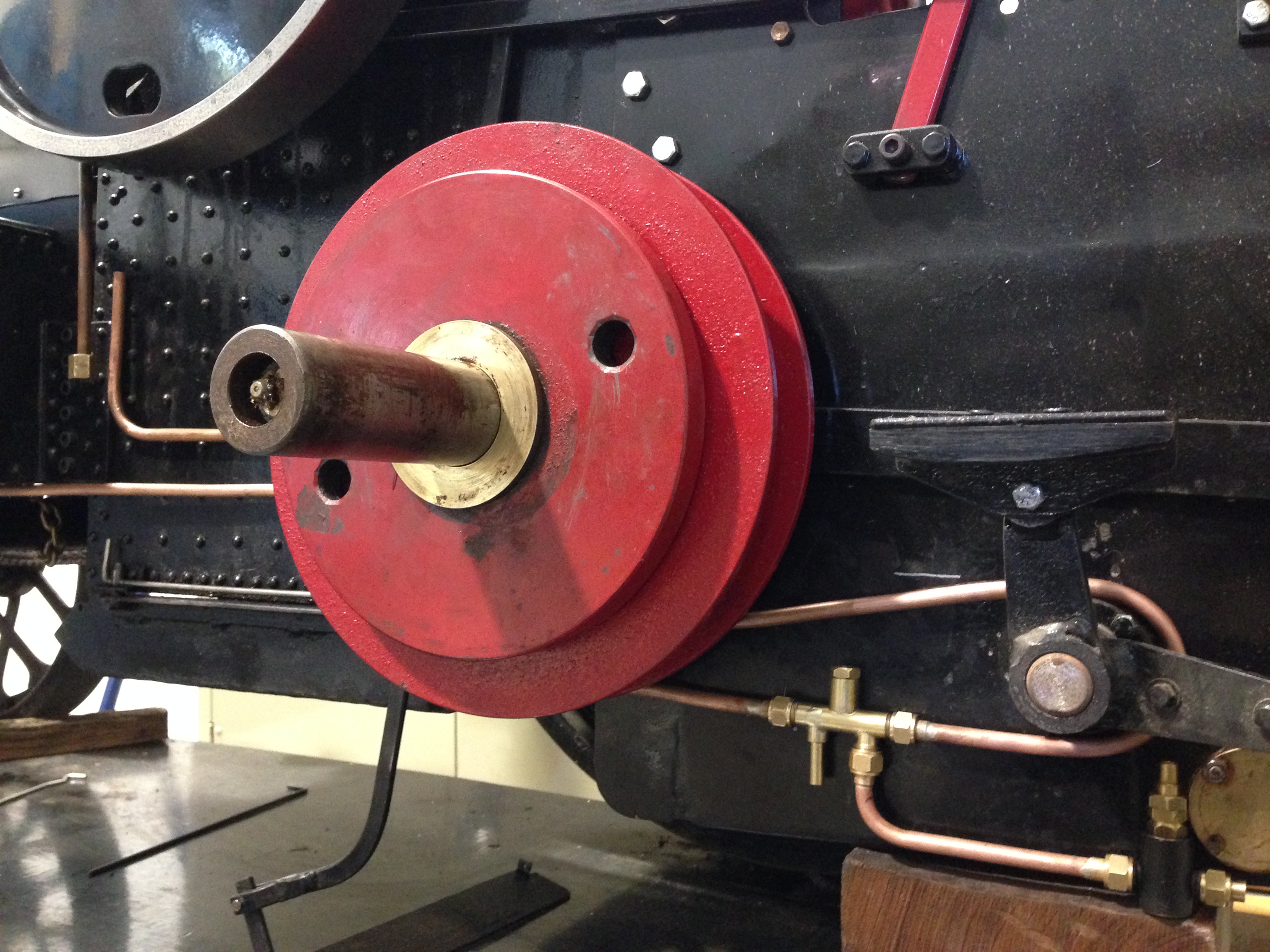
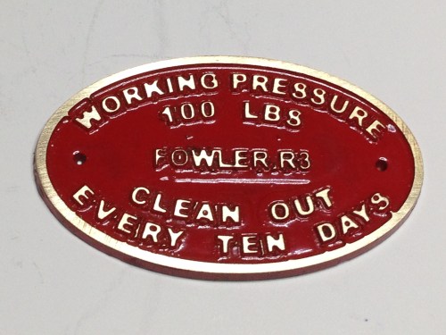
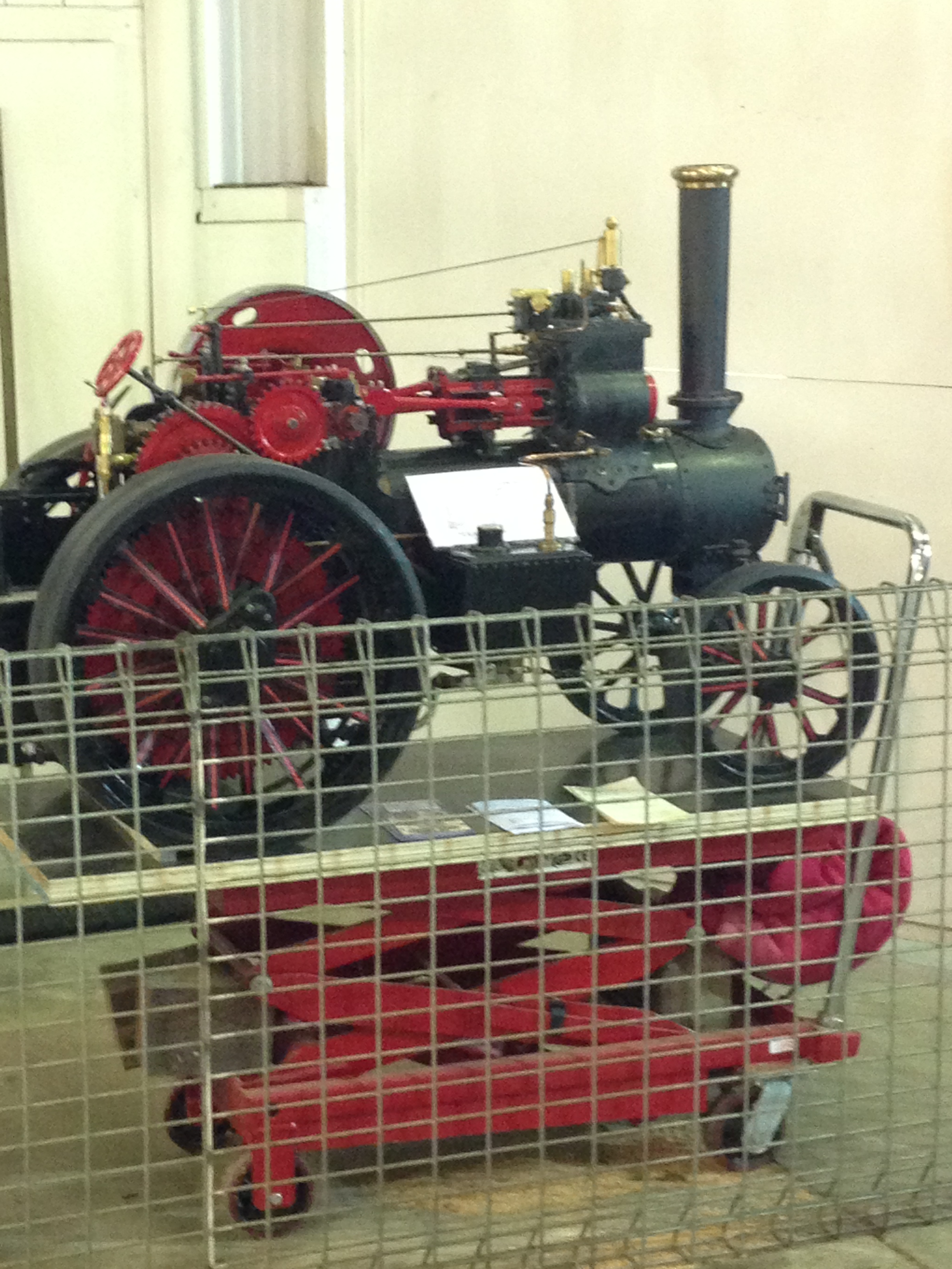
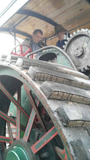
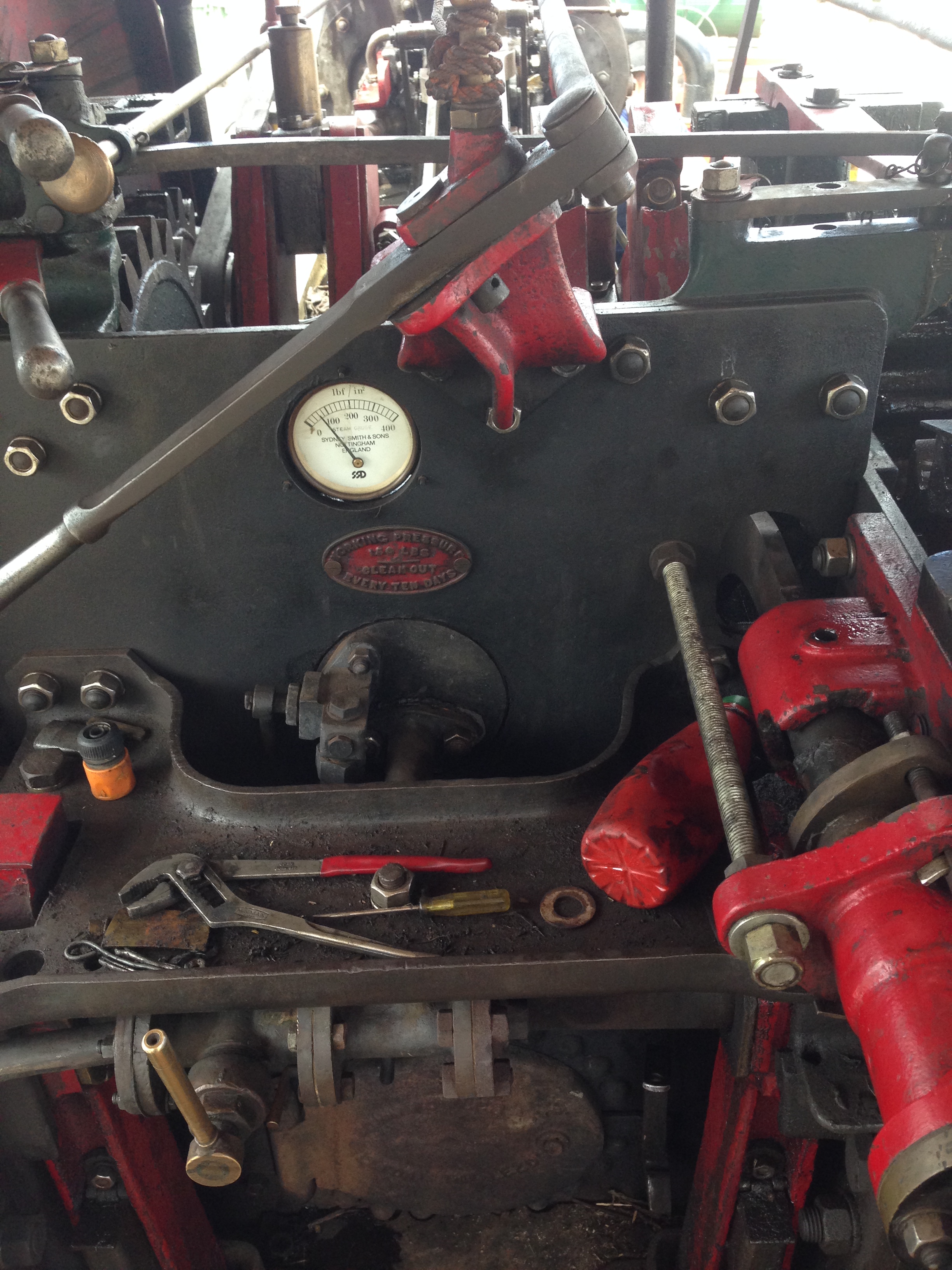
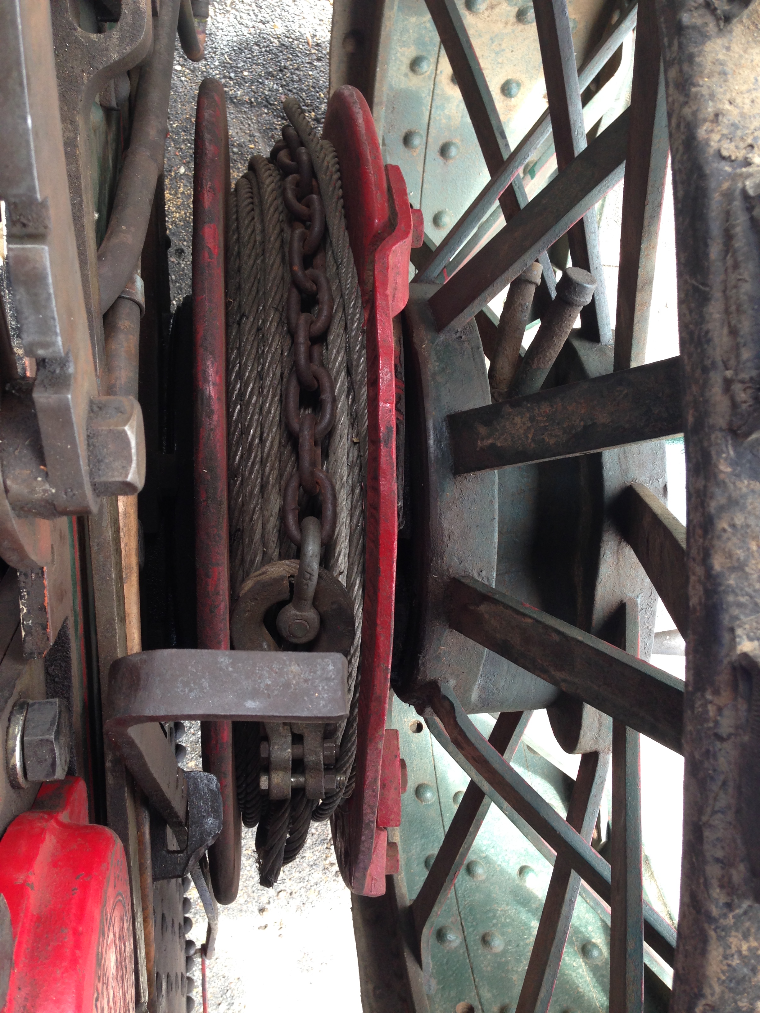
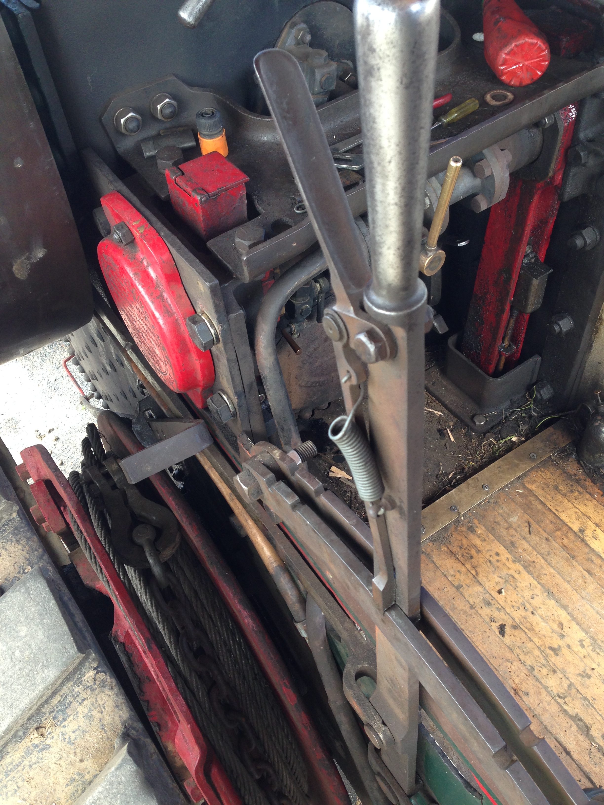
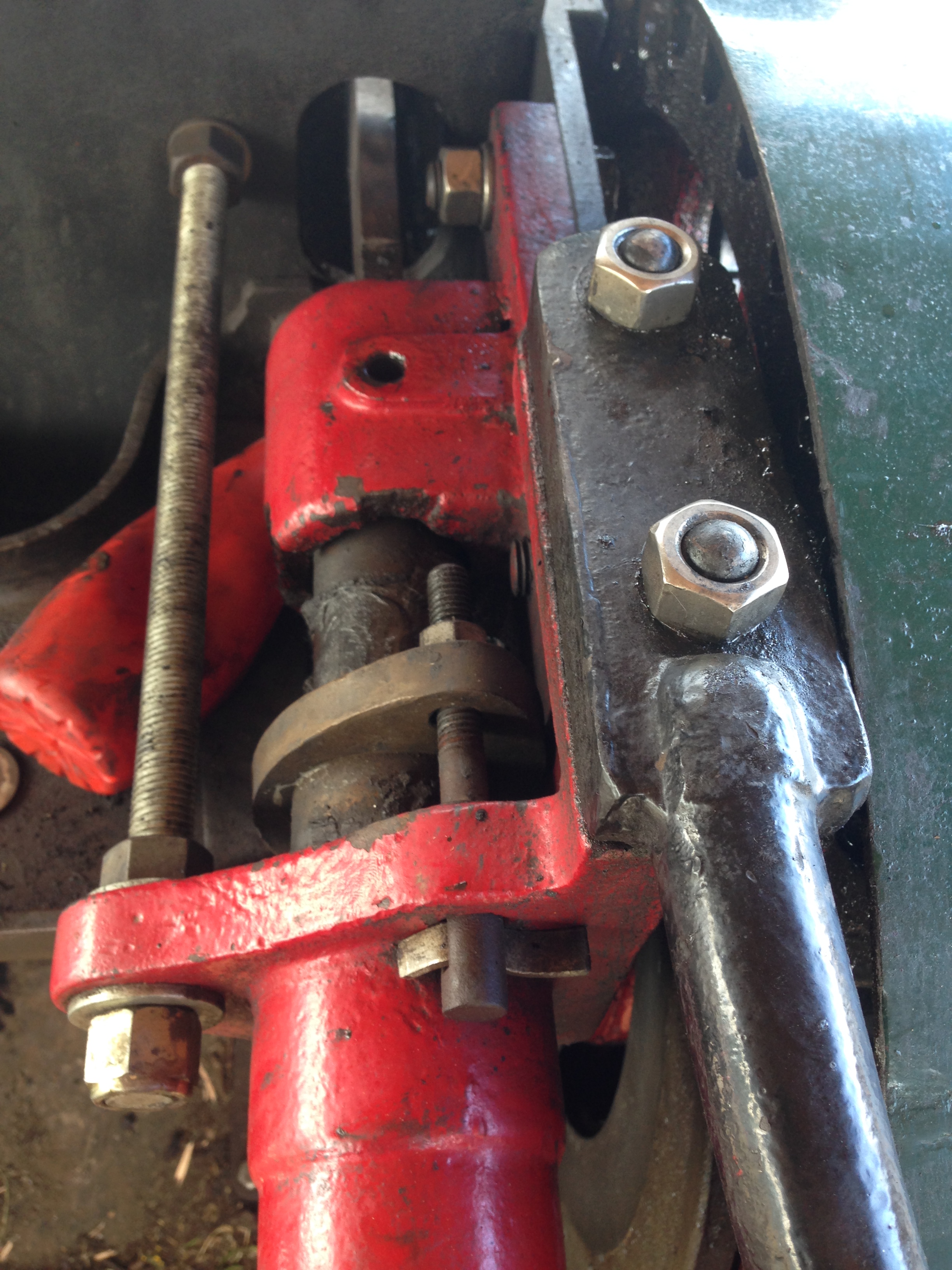
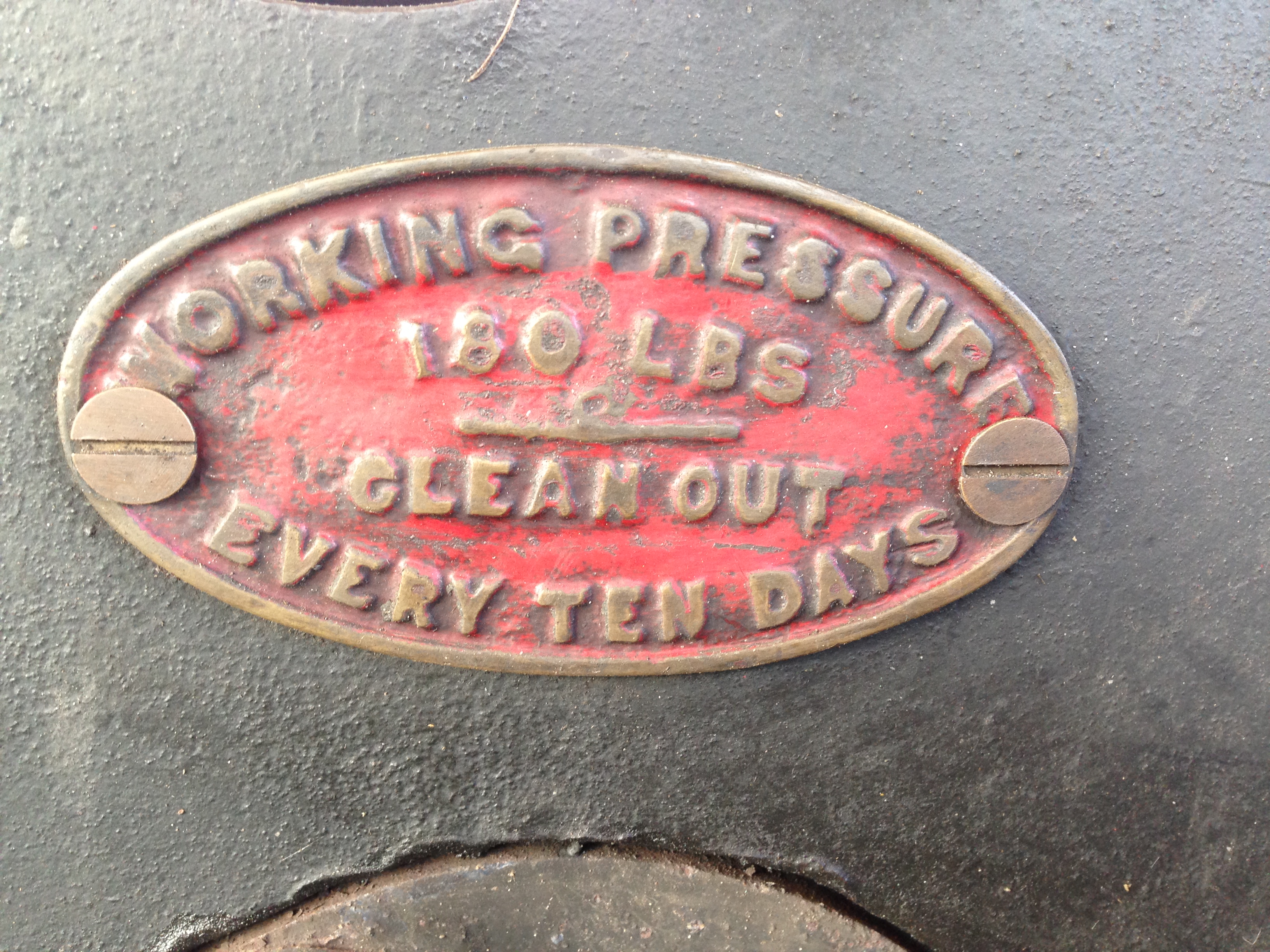
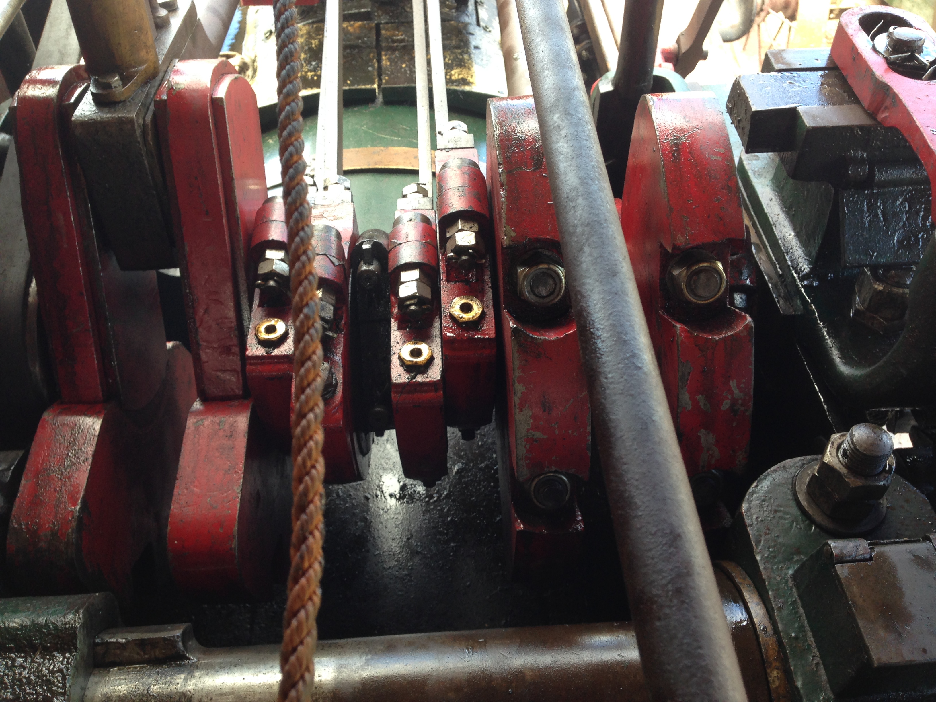
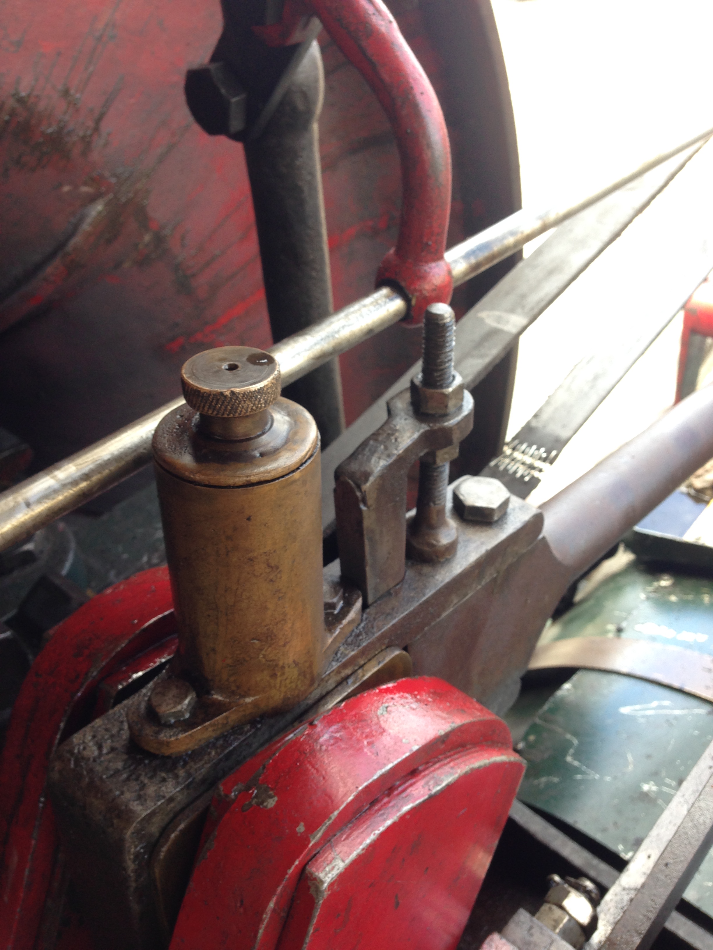
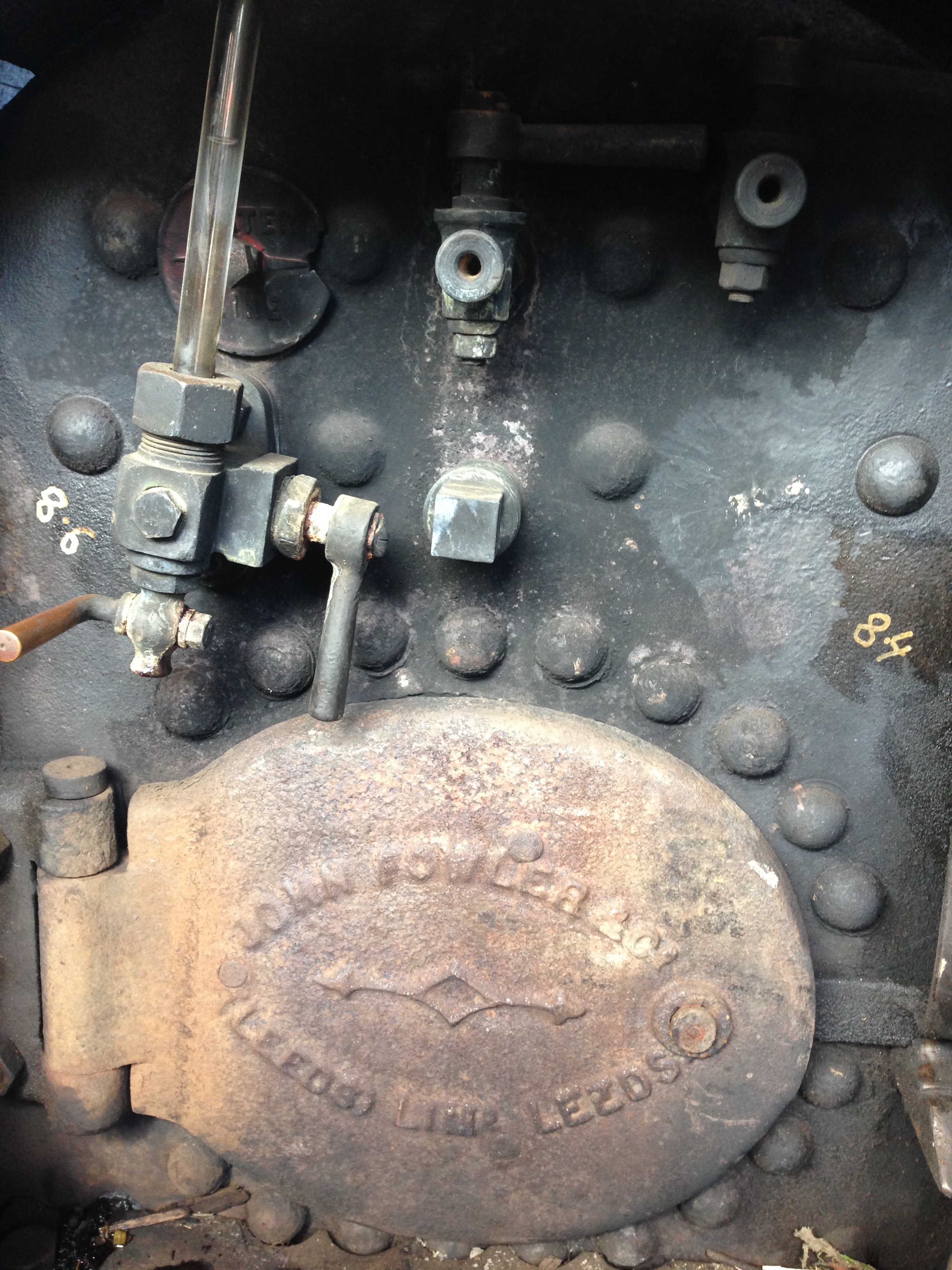
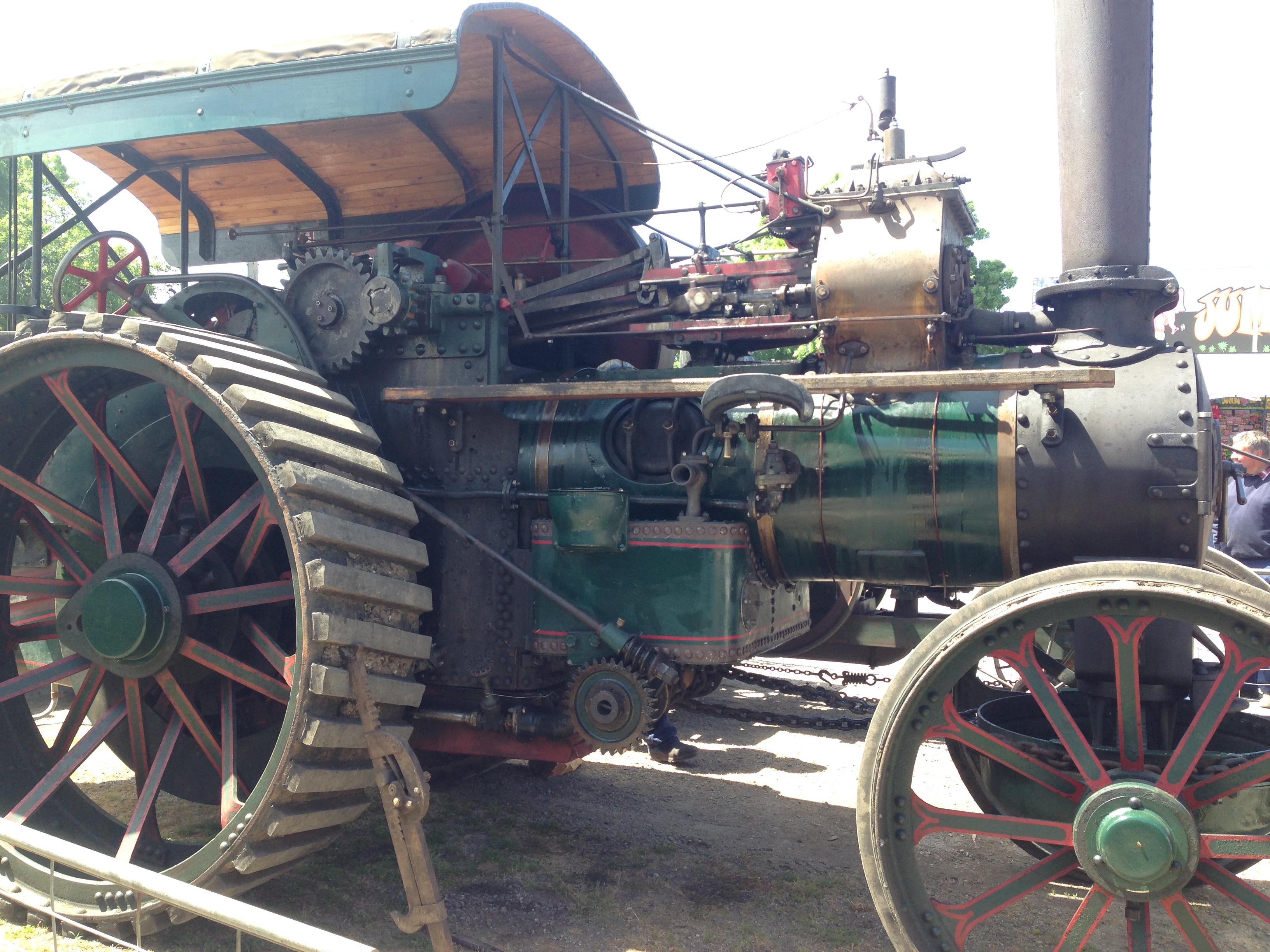
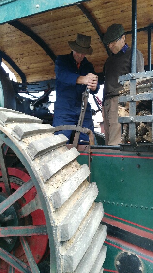
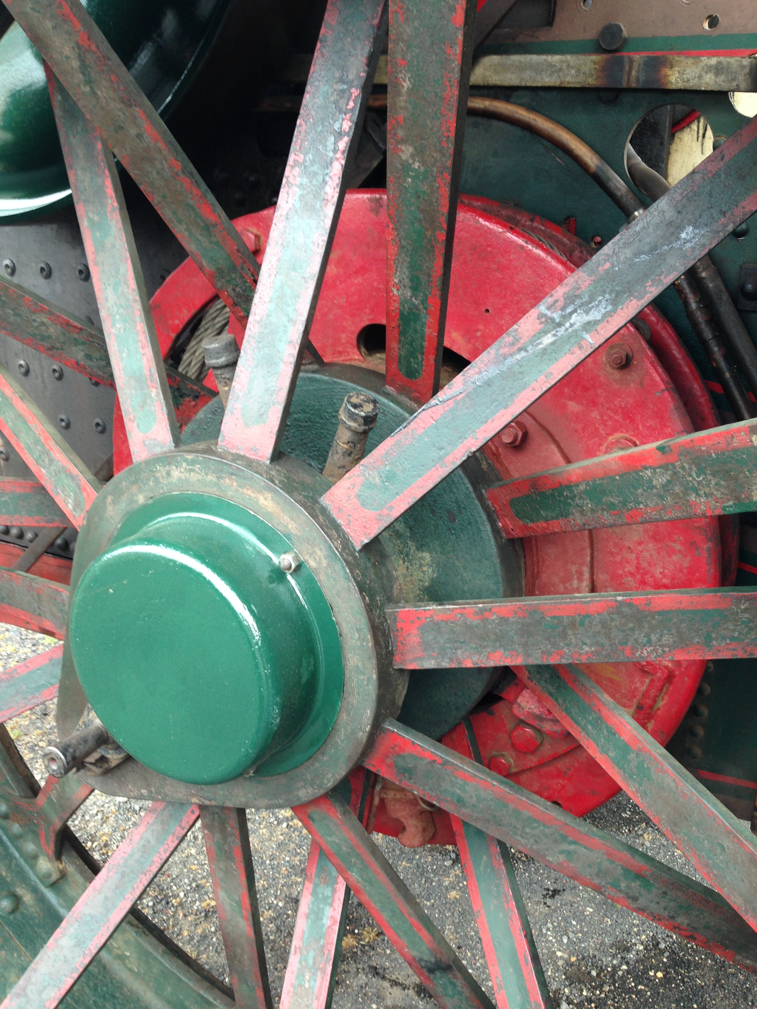
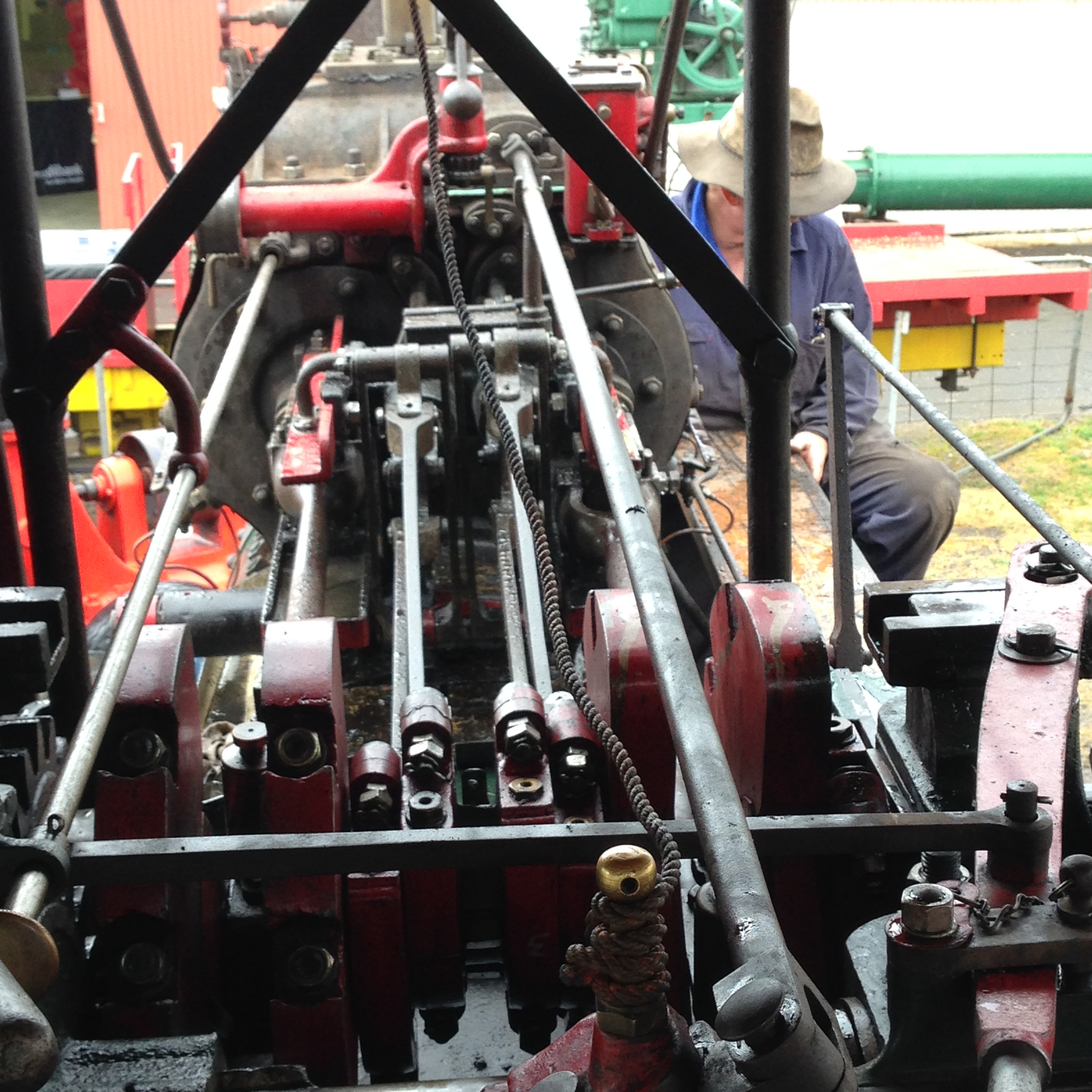
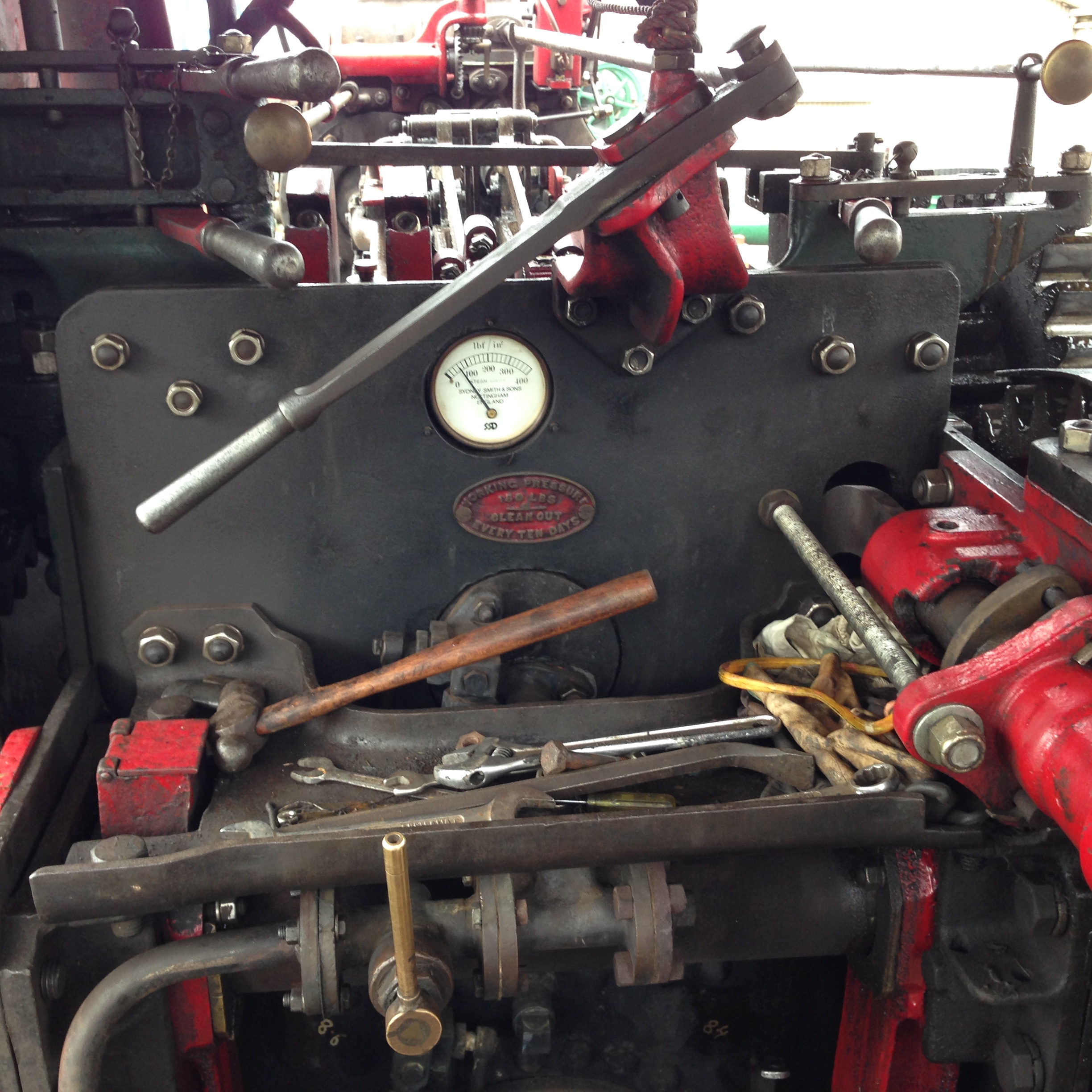
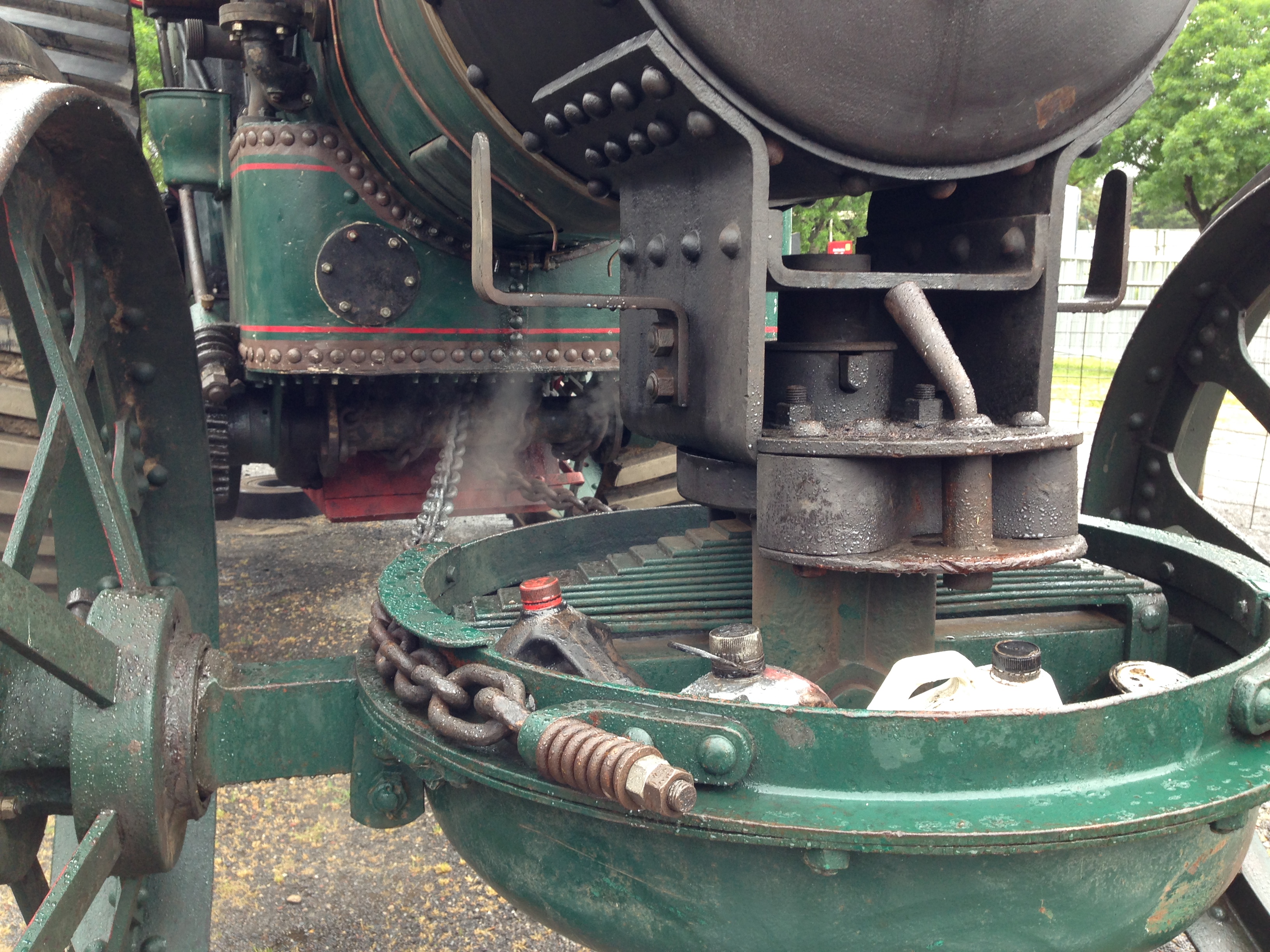
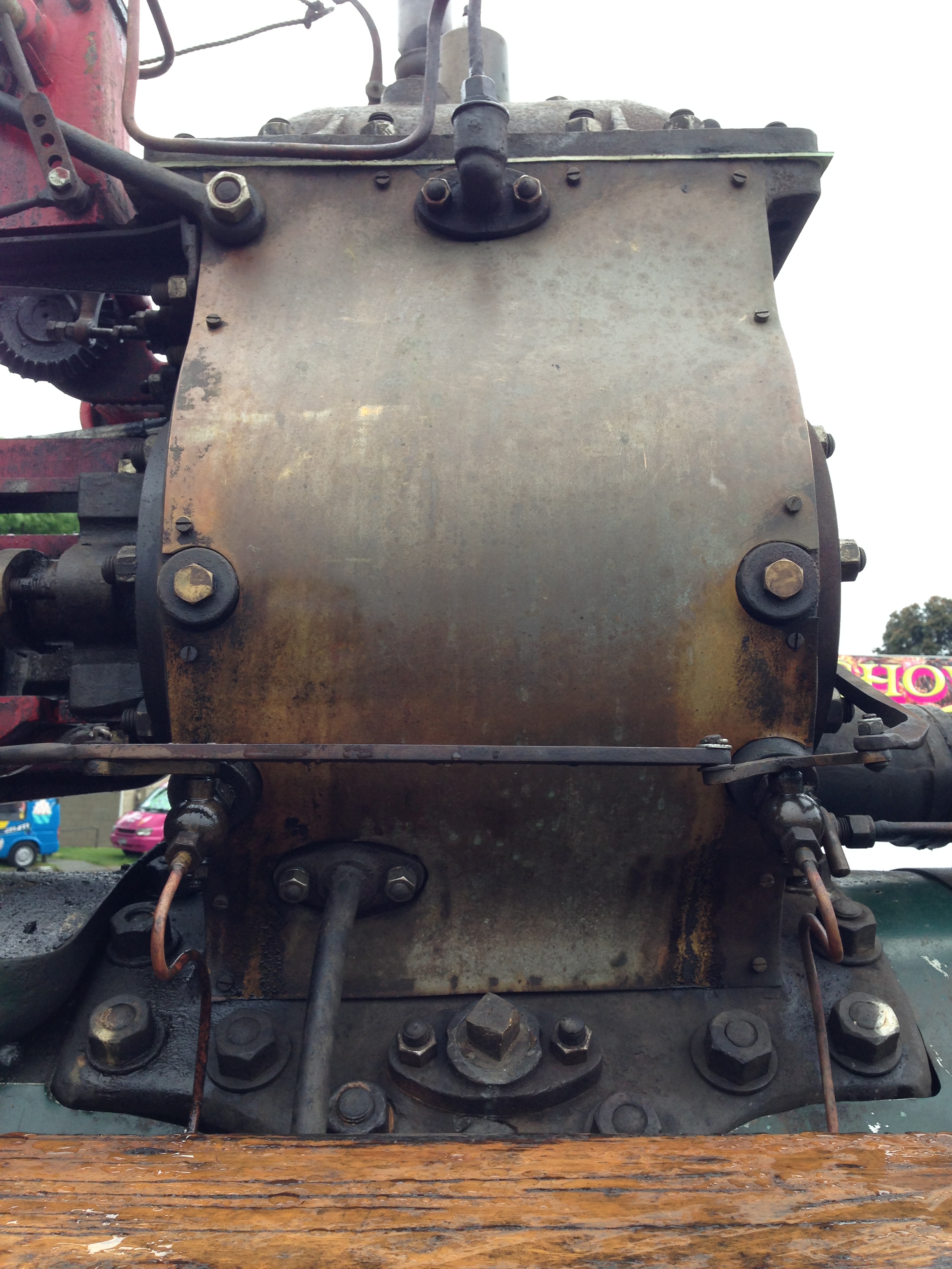
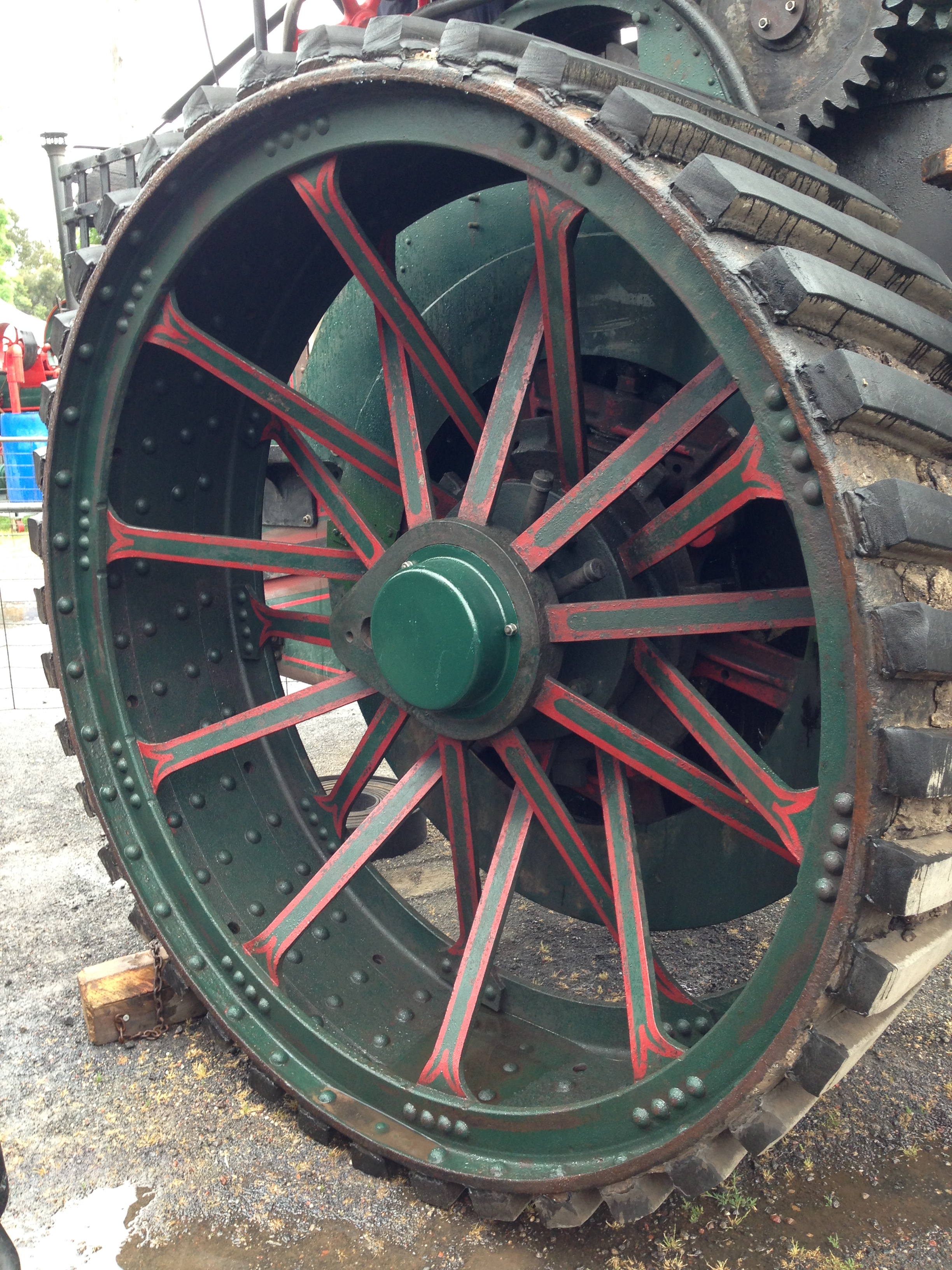
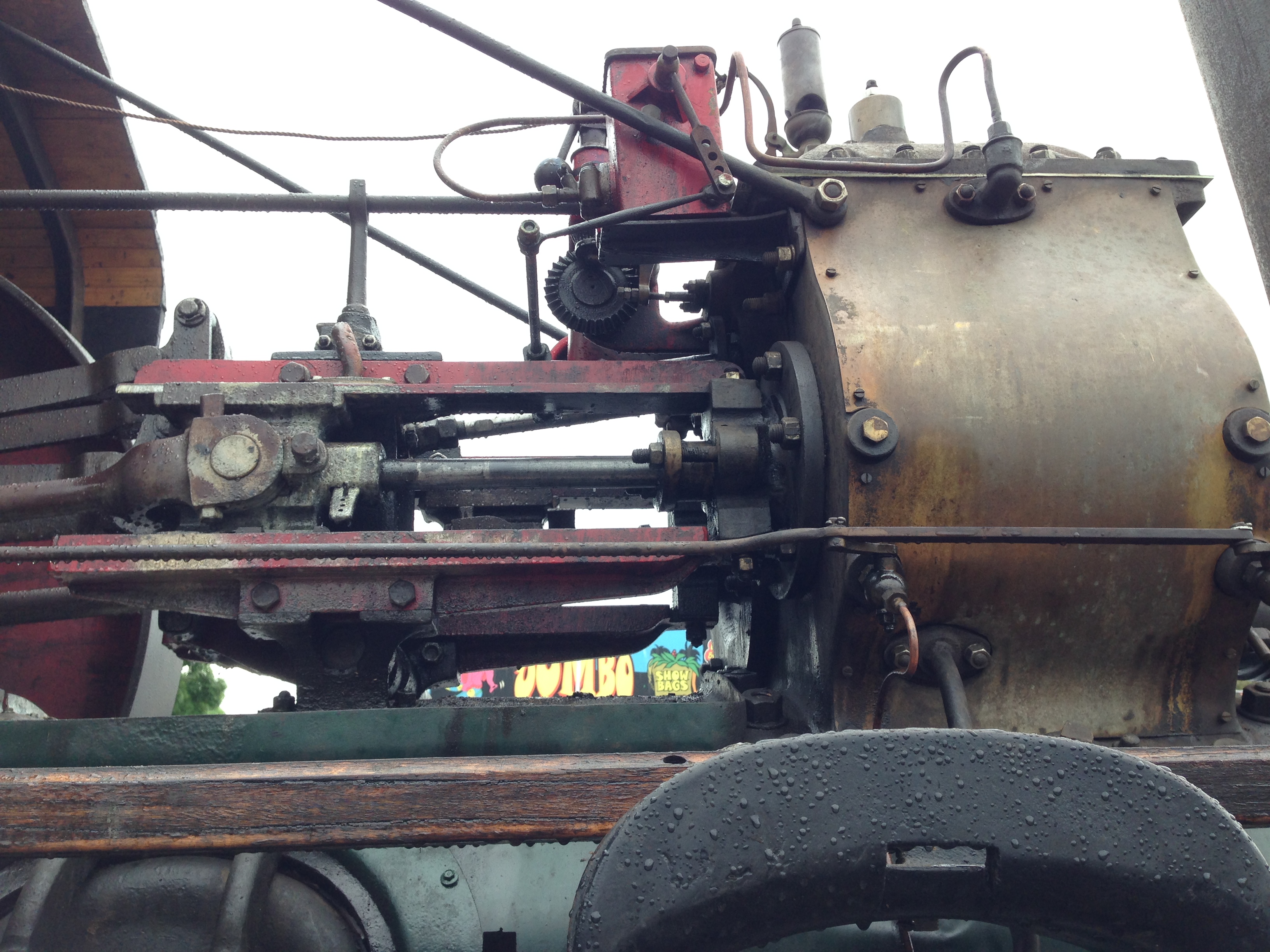
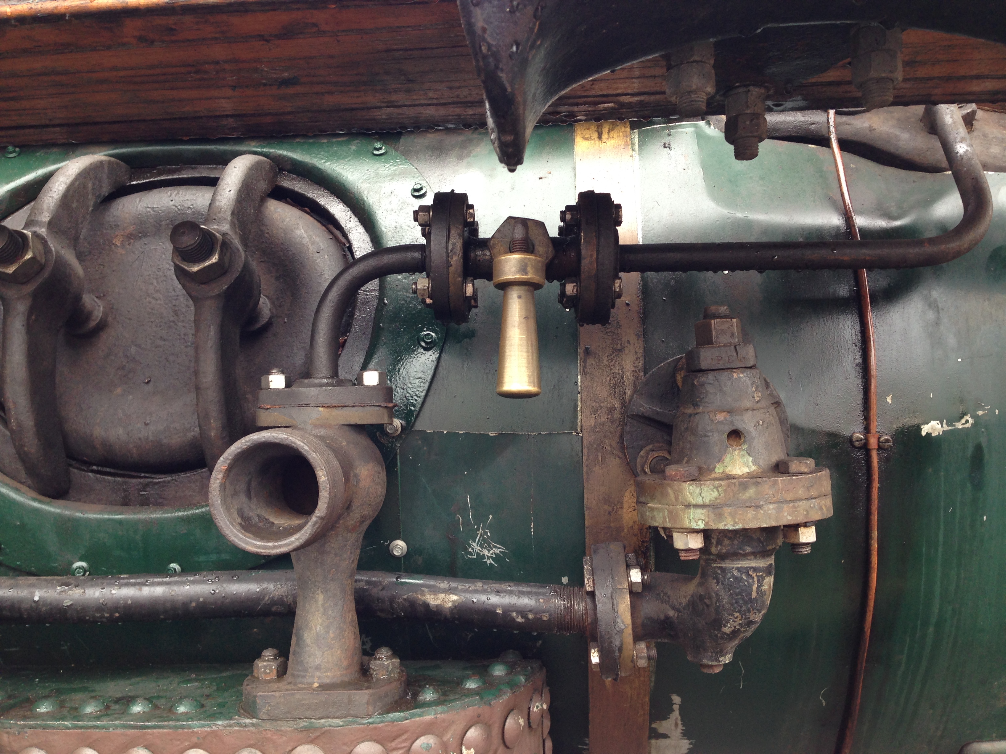
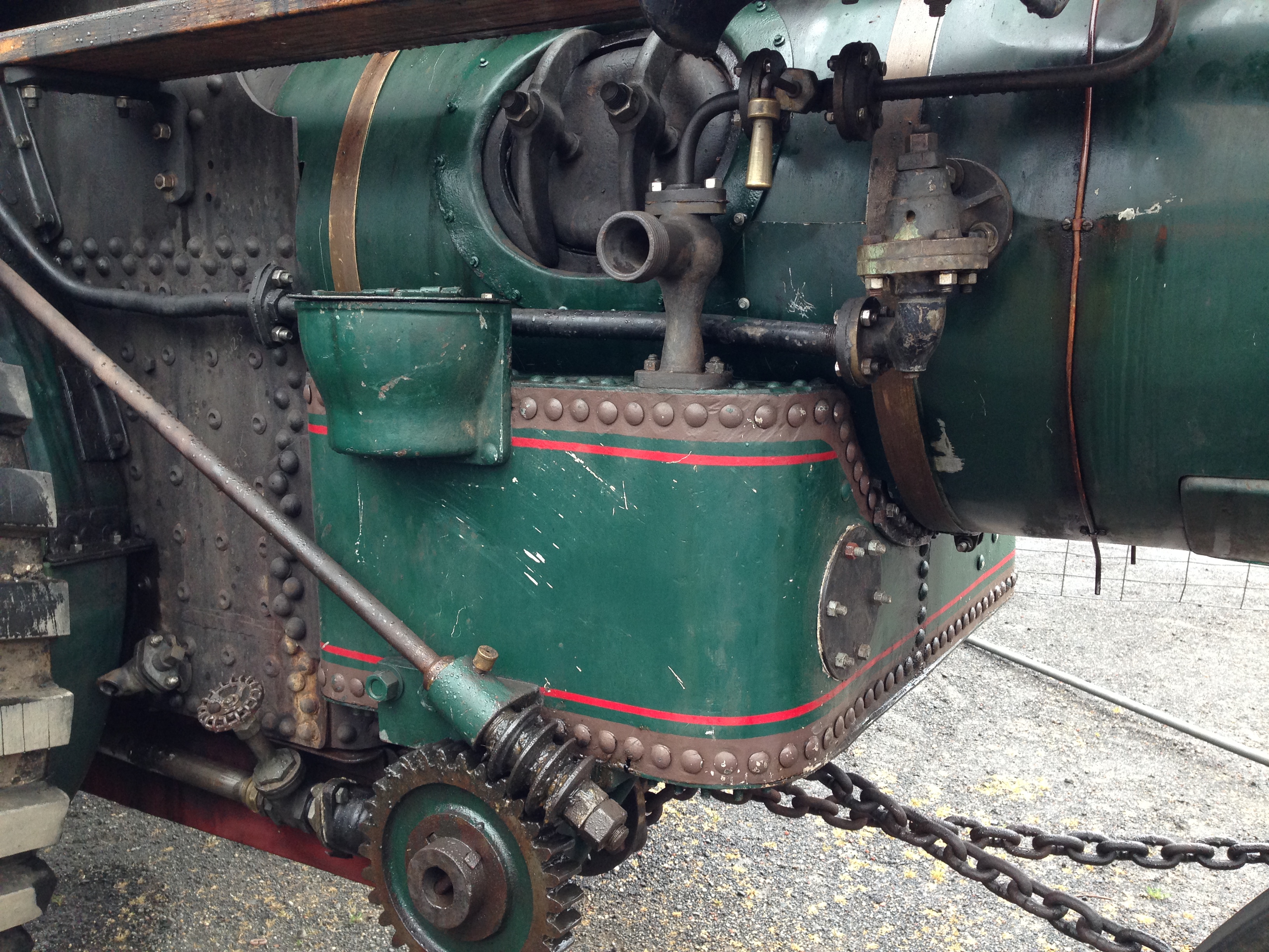
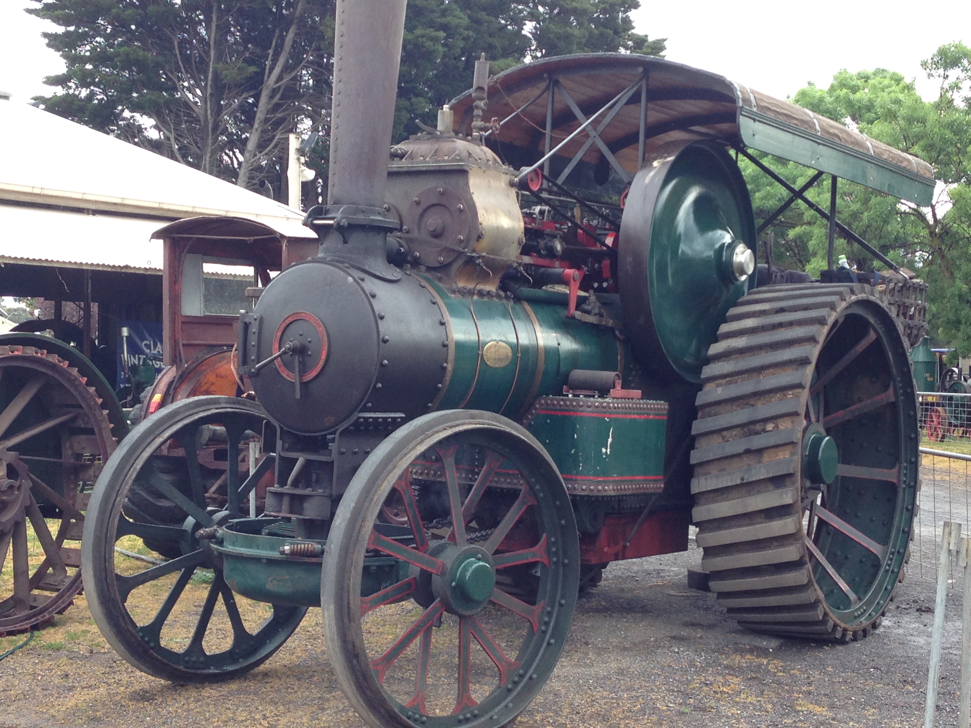
BTW. I have decided to sell my 3″ Fowler traction engine, tender, and coal, on a fitted 6’x4′ trailer with winch, toolbox and ramps. Full construction plans. It is running nicely with its new crankshaft, and has had boiler certification recently renewed until 2027. It has various improvements since this photo was taken, including working steam winch, steam injector, steam driven water pickup, new mechanical oiler, relocated hand pump, and more. Best offer around $AUD20k. Please, no tyre kickers. See previous posts for more pictures and videos. Inspection at Geelong, Victoria.

Making A Crankshaft -9

Almost finished.

When turning the big end journals the supporting block for each crank had to be heated to release the Loctite and remove the block, then re-glued in place after the journal was finished.

Then the mainshaft itself was turned.

But first the centres for the big ends were cut off, after making sure that the journals were totally finished!

In this instance I used the horizontal drop bandsaw, because I have not yet replaced the damaged blade on the vertical bandsaw. There is a piece of steel clamped in the vice, and the weight of the workpiece is sufficient to keep it in place during the sawing.

As you can see I used a flood coolant-lubricant. Here getting the dimensions close to final using a tungsten insert tool, at 235 RPM. At that speed balance weights were not required. Depth of cut was 0.5mm, and frequent stops for measurements, so it was a time consuming process. And to disassemble and clean the cross slide DRO glass scale. I reversed the workpiece where required to cut towards the headstock. I still do not know exactly what the steel grade is, but whatever, I had several changes of inserts as they lost their edge.

The final machining step (I hope), was to mill the keyway grooves. That took another 6 hours.

The CNC rotary table was very useful for setting the angles, and locking the shaft in position, on the mill. Two 6mm carbide endmills were required to cut the 10 keyways. Here I used a spray coolant, powered with compressed air. A little less messy than the flood coolant.

The crankshaft is almost ready to be installed in the traction engine. The support blocks to be removed finally. The shaft ends to be chamfered. And the crank weights to be drilled, tapped and bolted in place.

I had marked the eccentrics positions before the original disassembly, and here I have installed them approximately in the same positions on the new crankshaft. Of course they will require small adjustments later. The gears slide smoothly on their splines.

Doubtless there will be installation issues. The old crankshaft deviated from the plans in quite a few respects, and sometimes I was unsure whether to copy the old crankshaft, or to follow the plans. “Copy the old crankshaft” was the general advice, but there were some obvious discrepancies which had to be addressed. I can only hope that I have made correct decisions.

Making a Crankshaft -4

Not a lot more to show after today’s 5 hour workshop session, but the debulking with the bandsaw and mill is complete. The 26.5kg bar now weighs just over 7kg.

I started to bandsaw the remaining 2 blocks, and was just finishing a long cut when the sawing sound abruptly changed and the cutting stopped. WTF? Examination showed that the blade teeth were still sharp, but the teeth set on one side was gone. I think that there must have been a hard inclusion in the steel which stripped the side set. Whatever, that blade is stuffed. To make matters worse, I did not have a replacement on hand.

So, I had to revert to milling to remove the waste blocks. Just to reiterate, the blocks are 38.1mm x 38.1mm x 180mm so it was a lot of swarf again. But I am now using flood coolant, so the swarf was not red hot, and the 12.7mm carbide cutter survived intact. I was reminded why I normally avoid coolant however. It is VERY messy.

And it took a couple of hours so I reckon that I earned this one.

The remainder of the session was occupied by measuring and marking for the crank cut-outs.

Almost every surface of that solid bar will disappear when the turning in the lathe is done. The only surfaces which remain will be the bar ends, and the square surfaces where the counterweights will be attached, and they will not be visible.

The next step.

Do I cut out the crank slots, or do I rough turn the mainshaft? If I cut out the crank slots then I would install some packing blocks, then turn the mainshaft. I cannot see a significant advantage in either next step. Any thoughts?

Sir Ding Dong.

Not much happening in the workshop.  Visited by my middle daughter and family this weekend.

The boys are now 3, and responsive enough to not touch hot or moving parts and to watch out for wriggly pets.  I have seen 3 so far this season.

So we decided to give the boys some exposure to live steam.  They were intrigued by lighting the fire in the boiler, then adding wood and coal, and building up steam.  Nervously then enthusiastically operating the whistle.

Then the fun bit.

56331017_10155878660711901_6634981610481516544_o.jpg

Sir Ding Dong is a 3″ scale 2 cylinder compound steam traction engine.  It will tow this load easily.

We have had virtually no autumn rain yet, and the ground cover is very dry.  But it was a sunny and windless day, so it seemed safe enough to operate the steam engine.  No problems.  The kids, aged 3 to 69, loved it.


Oh, and by the way, the Trevithick dredger engine boiler passed its final inspection!  WooHoo!


Scale Traction Engine – installing a steam powered boiler injector.

My 3″ Fowler R3 Traction Engine boiler can be filled with a hand pump from the tender tank, by a crankshaft powered pump from the tender tank, or by a battery powered electric pump from the driver’s trailer.   The full size original R3 (see previous post for photos) has a steam powered injector, which uses boiler steam to suck up water from the tender tank using a venturi effect, then using black magic passing the steam+ water through some cones, increases the pressure which forces the mixture back into the  boiler.

Here is a link to a YouTube site which sort of explains how the black magic works.

And this is the steam injector on the full size R3 Fowler.

IMG_5916

And this is the injector which I bought for the 3″ scale Fowler.

FullSizeRender 6.jpg

It is a vertical injector, with connections for 1/4″ (6.35mm) pipes.  But I did not use it because it protruded too far underneath the tender.  So I have used an identically sized horizontal injector, which is shown below, during installation.  The full size original also appears to be horizontal.   The black fitting connected is the water inlet valve.  The control handle will extend above the rim of the cockpit.

IMG_6207.JPG

IMG_6205.JPG

The red thing is the winch, and its driving disk.  Winch engaging pins have never been completed, another job for later.  The rear wheel has been removed.  The injector pipework passes between the winch drum and the hornplate, with just enough clearance.  Running the pipe around the brake axle seemed like a good idea at the time, but I am not so sure now.  When painted black it will not look so odd.   The water connection with the tender tank is yet to be made, as is the steam supply connection.  A few more hours.

Geelong Classic Truck and Vintage Machinery Show. Day 1.

I was busy minding the 1:4 scale Fowler traction engine today, at the show, but these were a few items which were of particular interest to me, of the hundreds on display.  Not to mention the tractor pull, the Liberator WW2 engine demo, and the magnificent vintage trucks and cars.

Peugeot 403.JPG

Peugeot 403.  My first car was one of these.  For its day it was reliable, rugged and advanced.  Won the first Redex rally across central Australia in 1956.

Marshall on low loader.JPG

Marshall Compound traction engine on low loader.  The traction engine is completely original, unrestored.  Needs a lot of work.

Marshall smoke door.JPG

Marshall smoke door

Marshall engine .JPG

Marshall engine

Marshall pressure gauge.JPG

Marshall pressure gauge

marshall throttle control.JPG

Marshall, from the driver’s position.

Fowler & son3.JPG

Fowler R3 and baby R3

The Boiler Inspector.

Today I loaded the Fowler 3R traction engine onto its trailer and drove to Werribee, to have an official inspection of the boiler.

This is not a legal requirement, because I can operate my traction engine  whenever I please on my own property.  But all model engineering Clubs and Societies require a current certificate before they will permit steam engines to be operated at their meetings.

The maker of my traction engine had the boiler inspected and passed about 18 months ago, but that certificate has now expired.  So it needed re-certification.

The original test pumped water into the boiler at double the maximum operating pressure to test the boiler for leaks and distortion.  The boiler is actually designed to withstand pressures of EIGHT times maximum operating pressure, so the safety factor is reassuring.

But, boiler explosions are horrific, so the caution is understandable.

My boiler is made of copper, thus avoiding the problem of steel boilers which gradually becomed thinned by rust.   And my boiler seams were joined by silver soldering, which, if expertly done is as strong as the parent metal.  As a matter of interest, the maker of my boiler told me that he had used $AUD1000 of silver solder in the construction of the boiler decades ago!

The test today involved pumping water into the boiler at 25% above maximum operating pressure, and holding it there for 20 minutes, checking the boiler for leaks and distortion.  It passed that test without problem.

The next test was for the functioning of the safety valves.  I had cleaned them and replaced the balls and polished the seats, and I had seen them blowing off when the pressure was above 100psi, so I was fairly confident that the certification was “in the bag”.

So the fire was lit, and after some coaxing because I had stupidly forgotten to bring the chimney blower,  the  steam pressure was raised to 100psi.  The safety valves started venting off.  But, the test is fairly demanding.  The fire was roaring, the steam blower was turned on full, and the pressure continued to rise.  It rose to 120psi which fails the test because the safety valves should have released enough steam to keep the boiler pressure at 100 psi or 110psi maximum..  Some adjustments to the safety valves did not fix the problem.

Some machining will be required to fix the valves, but after consideration I have ordered brand new safety valves and the test will be re-done when the new ones are fitted.

The boiler inspector was quite particular and proper, and very helpful.  I am grateful that this safety issue was detected, and I totally agree that it has to be fixed.  Thinking back to my problem of about 1 month ago, when I “dropped the fire”, (see “Holes in Swiss Cheese) I now believe that the problem was partly caused by the inadequate safety valves.

Add one more hole to the Swiss Cheese theory of disasters.

IMG_5873.JPG

The inadequate safety valves.

IMG_5872

The safety valves AND the oiler were replaced.

The new safety valves arrived today.  Warrick Sandberg valves.  I will install them later this week, and fire up the Fowler R3.

IMG_5873

The old safety valves.  Not up to the job.

new safeties.JPG

The new safety valves.  about the same dimensions but the exit holes are bigger and the spring tension is adjustable and lockable.  

And another thing.  I noticed this label near the pressure gauge of the full size Fowler R3.

IMG_5772

So I made this one today.  Slightly modified the information to suit my 3″ scale Fowler.

working pressure new.JPG

My enamelling technique could improve, but it will do.

Fowler R3 at The Geelong Show

IMG_5788

I took my Fowler R3 3″ scale traction to the Geelong Show, and here it is on display.

The R3 is a bit of an uncommon traction engine, so I was rather surprised, delighted and awed to find a full size R3 on display also.  Of course I met with the owner and spent a lot of time talking to him and examining the real McCoy Fowler R3.  Apart from the size difference, the similarities were striking.  Even the colour scheme was similar.  And the full size machine was a heavy haulage model whereas mine is a road locomotive.

I found the numbers were interesting

weight     250kg/18tonnes

length 1.5m/ 6m

towable load 250kg/60 tonnes

cylinders 2/2

boiler pressure 100psi (copper)/180psi (riveted iron)

year of build 2016/1911

IMG_5739 2

Me, getting a driving lesson from the owner, Graeme Brown

IMG_5767

The firebox door, throttle, looking forward

IMG_5768

Winch

IMG_5769.JPG

Forward/reverse lever

IMG_5770.JPG

Water pump, crankshaft driven

IMG_5772.JPG

IMG_5774.JPG

crankshaft with its cluster of big ends and valve rod eccentrics.

IMG_5777.JPG

Con rod big end hardware

IMG_5781.JPG

Fire box door and water level sight glass

IMG_5783.JPG

Fowler R3 heavy haulage engine.  spent most of its working life in and around Ballarat, Victoria, Australia

IMG_5787

IMG_5696

Rear wheel hub and winch

IMG_5690

This could be a photo of my engine, but it is not

IMG_5691

IMG_5689

Lubricant and tool storage area.  Actually the front suspension and steering drum.  I imagine that the springs are to protect the  gear teeth.

IMG_5688

Not sure that the brass cylinder cover is kosher.

IMG_5687

The wheels hardly dented the grass during the grand parade.

IMG_5685

The engine mechanicals, oiler, whistle, and hose support.

IMG_5684

Boiler inspection hatch, and water intake.

IMG_5683

Belly tank, steering gear

IMG_5700

The engine could be used as a cathedral reliquary

And a series of non-edited videos, to recapture some magic moments.

Traction Engine Lamp Lenses

My Fowler 3R, 1:4 scale traction engine had nice little lamp bodies, but they looked a bit odd because they had no glass lenses.

Old photographs suggested that the lenses were convex, not flat, so cutting out some circles in flat glass or perspex was not appropriate.

But in my junk store, I had been saving some perspex balls which had originally been part of a desk lamp.

IMG_5675

The perspex (?Lexan) balls were 50-60mm diameter

IMG_5676

With a 12mm hole

I needed the lens to be 22mm diameter, and I could not figure a method of holding the balls in a lathe chuck without damaging the Lexan surface.

So I milled the outside diameters.

IMG_5670.JPG

Holding the Lexan ball in the mill vice, and milling the 22mm outside diameter (CNC of course).  Then it was easy to hold the machined cylinder in the lathe chuck (collet chuck actually), and part off an 8mm thick lens.

The parted off Lexan lens was too opaque on its parted off surface, so I spent some time with 400 grit, then 600 grit wet and dry paper to remove the parting marks.   Surprisingly, it became fairly transparent.  If I had some 1000 grit paper on hand I expect that it would have been quite transparent.

Then I pushed the lenses into the lamp bodies, and this is the final appearance.

IMG_5671.JPG

They look like they have a squint, but that is a photographic illusion.  They are pointing straight ahead.

IMG_5673.JPG

Not bad Eh?  The side aperture needs glass or perspex.  I have some LED’s on order to provide lumens.  Not sure how I will arrange the batteries.