johnsmachines

machines which I have made, am making, or intend to make, and some other stuff. If you find this site interesting, please leave a comment. I read every comment and respond to most. n.b. There is a list of my first 800 posts in my post of 17 June 2021, titled "800 Posts"

Tag: Turkish bombard

Next Project?

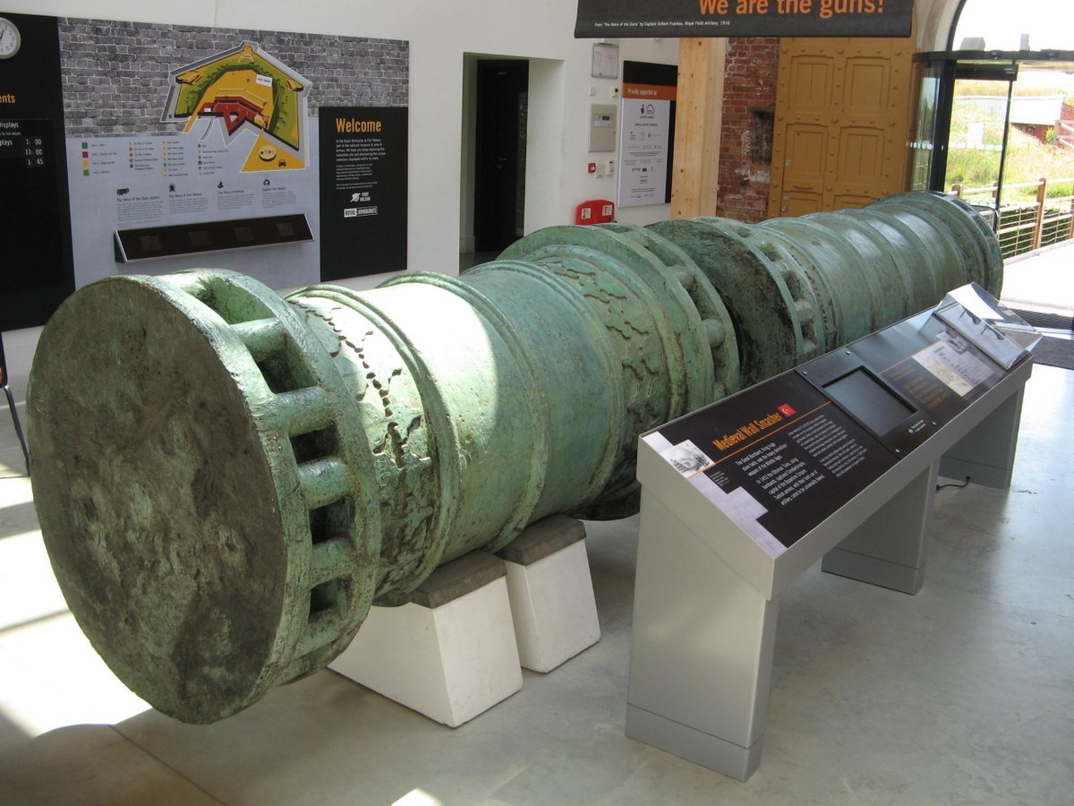
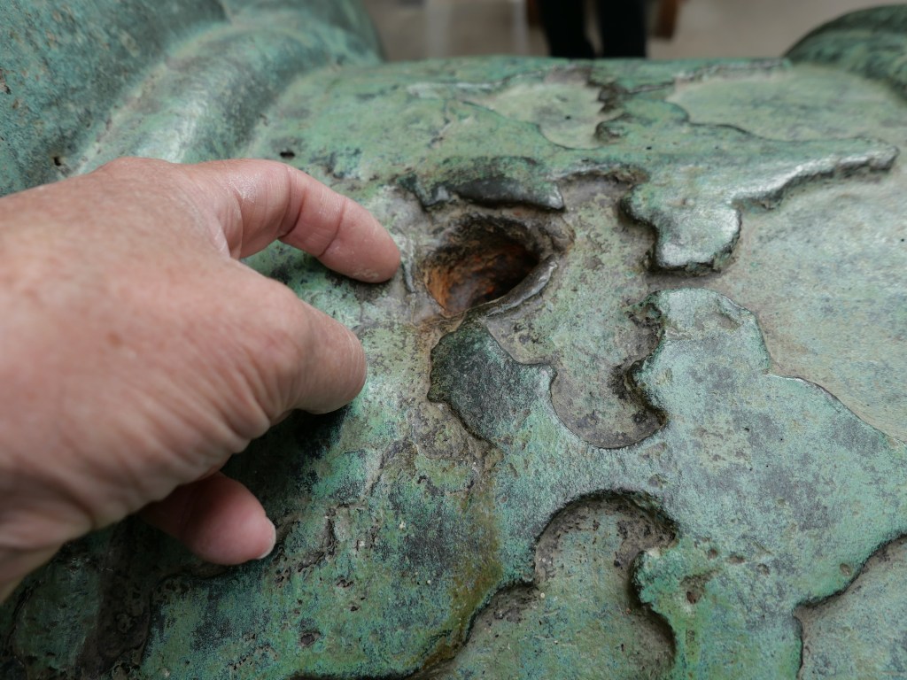
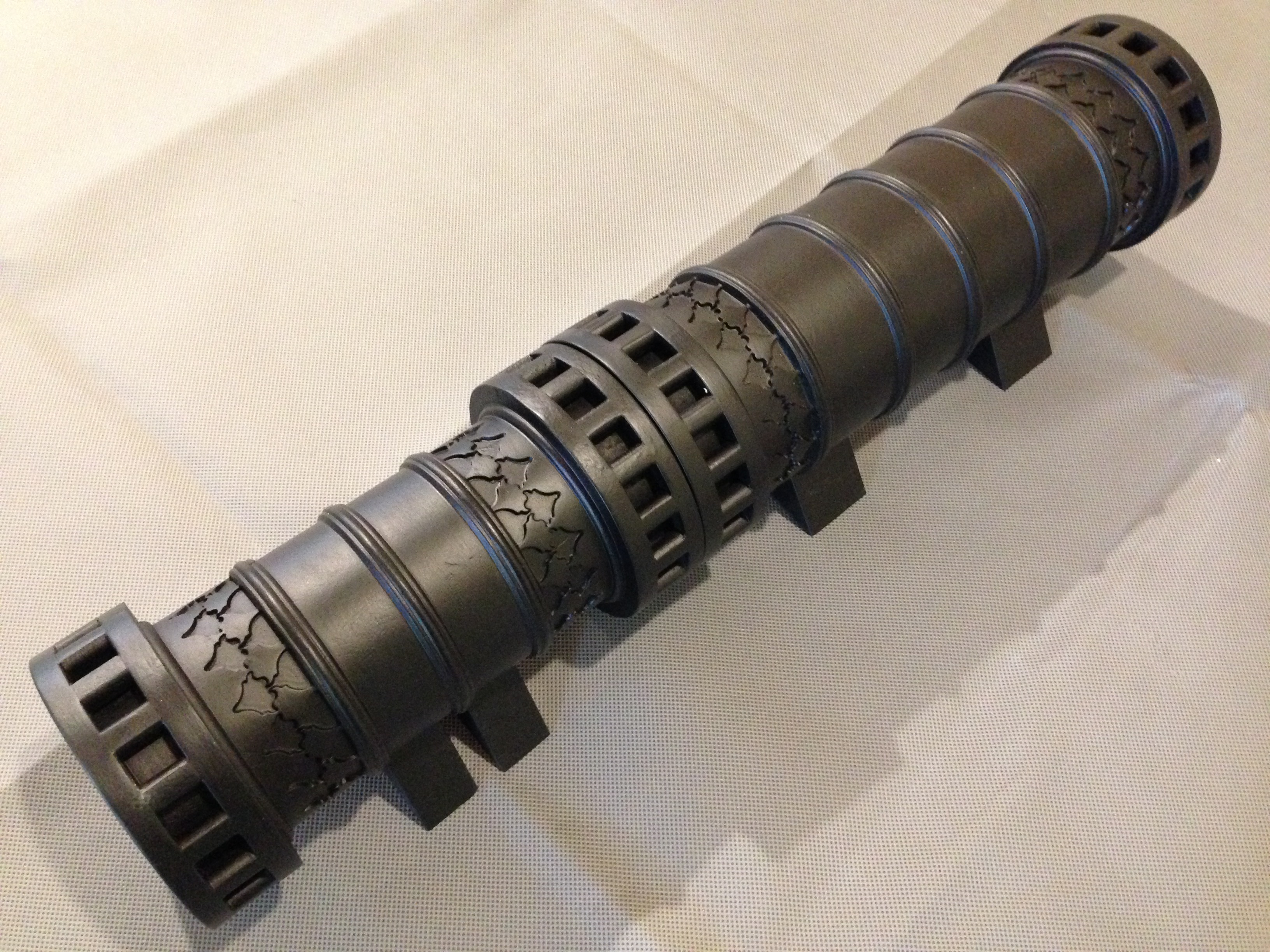
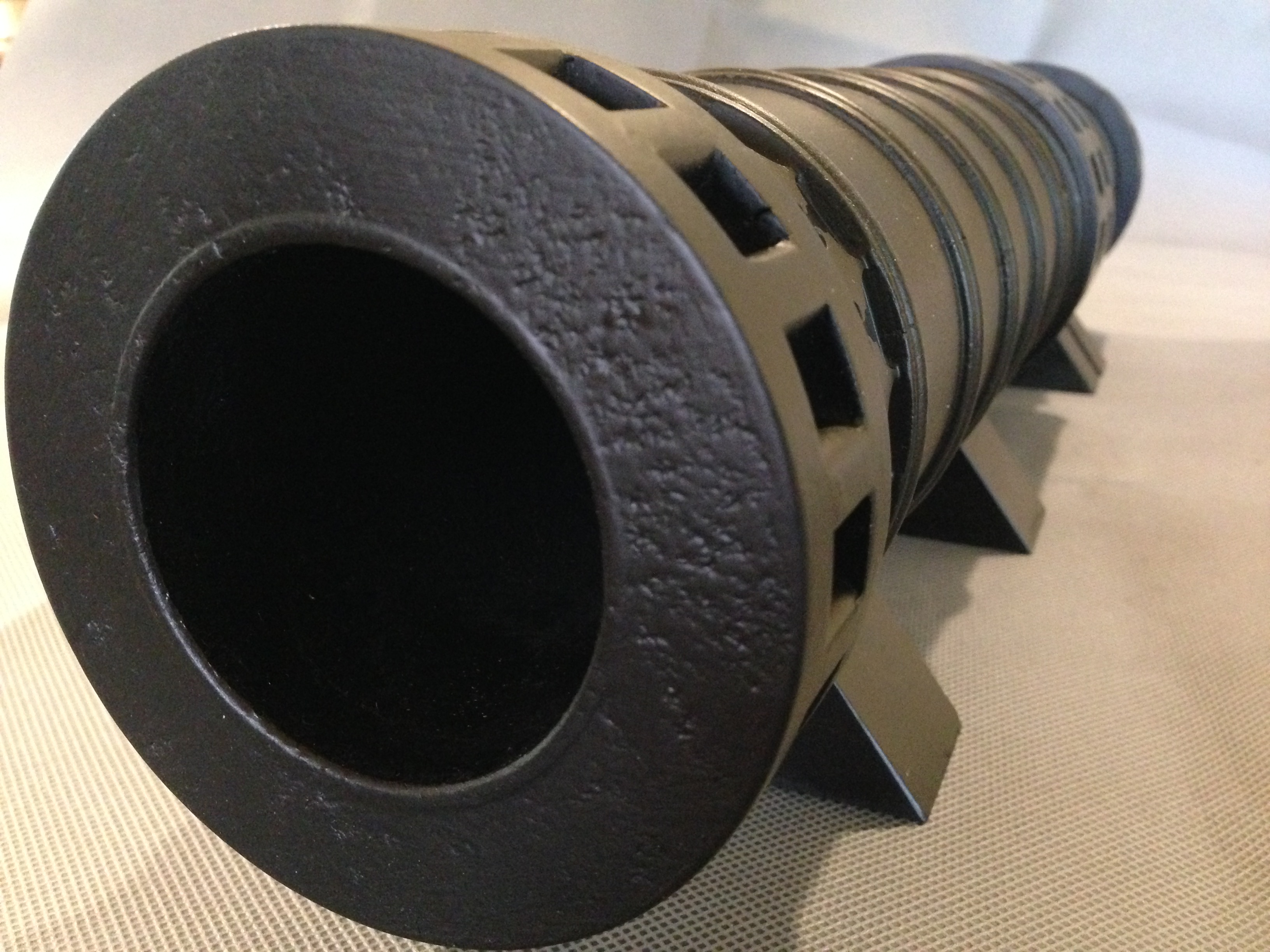
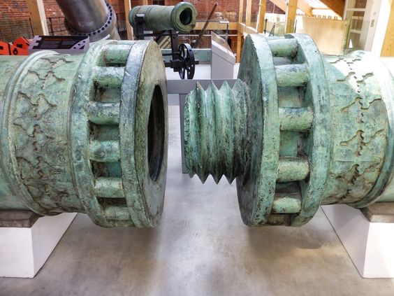
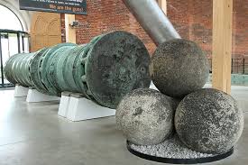
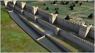
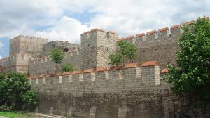
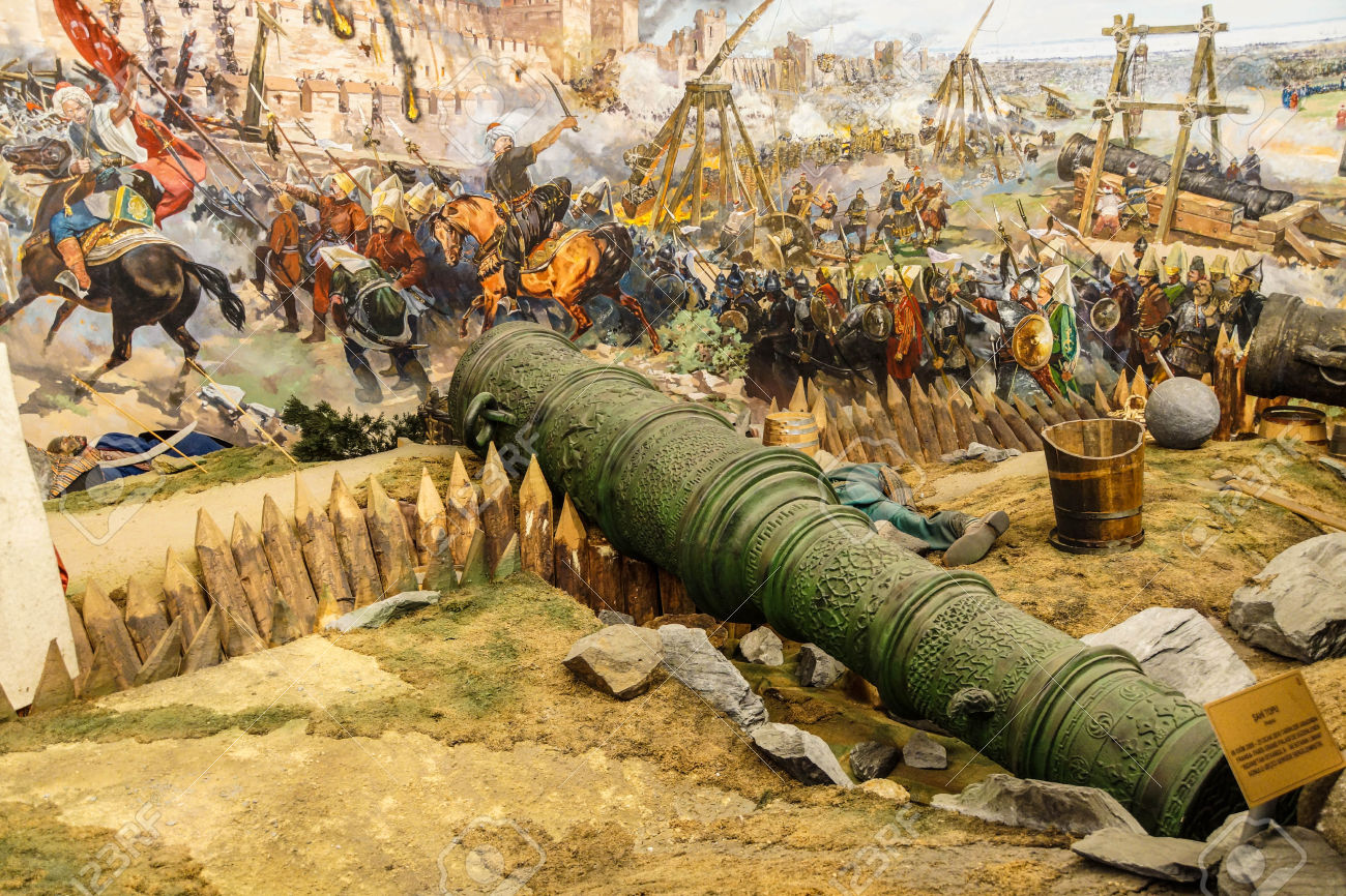
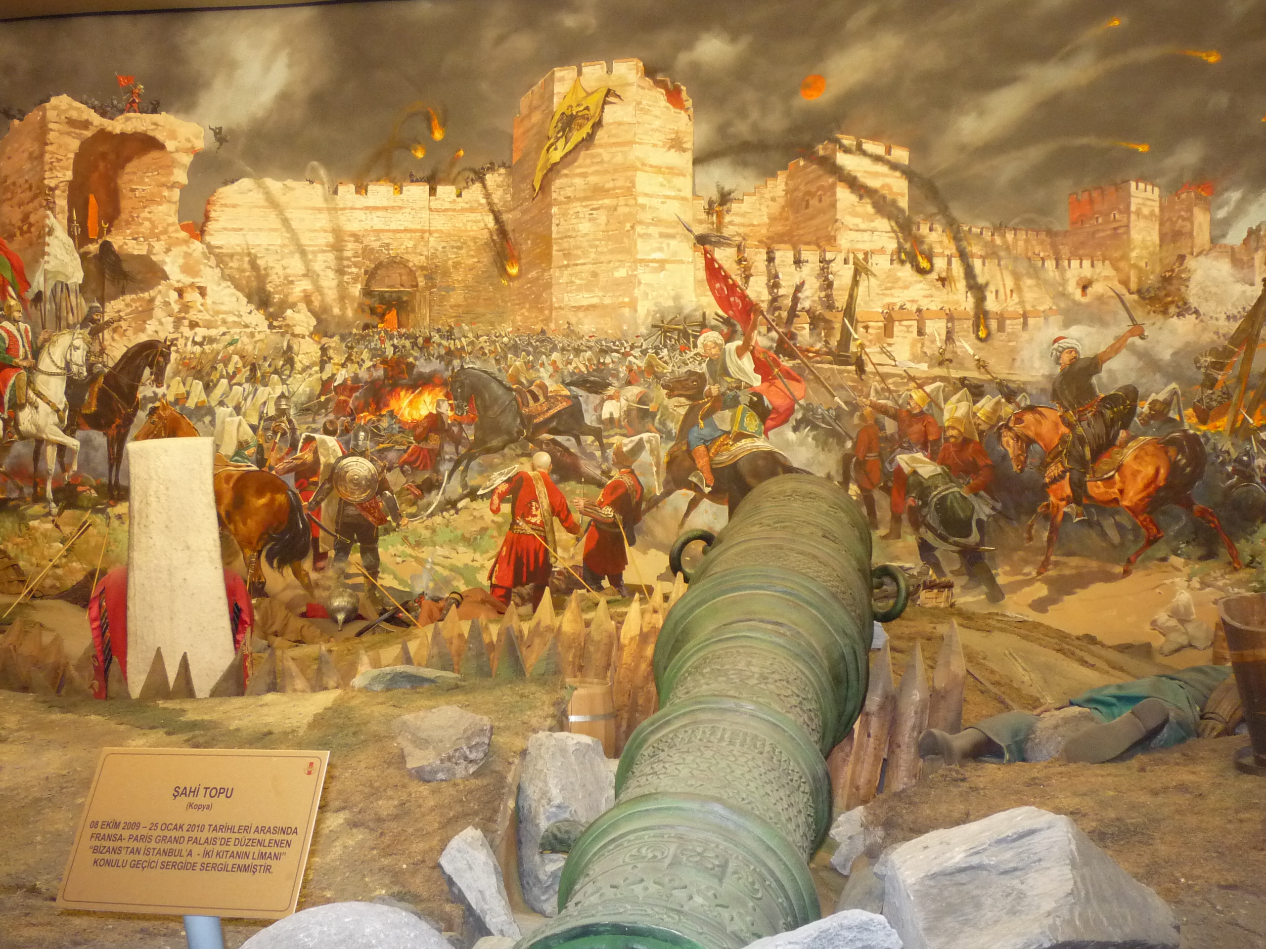
I made a 1:10 model of this Ottoman bombard a few years ago. This one was made in 1465, and is thought to be a copy of the bombards which brought down the walls of Constantinople in 1453. This one resides in the Royal Armories Museum at Portsmouth, UK, and I photographed and measured it in 2019. It has a bore of over 600mm, and fired stone balls of over 350kg.

Last used in anger against the Brits in 1807, where it and others like it, were instrumental in preventing a British fleet from invading Istanbul (renamed from Constantinople). How many weapons have an active life of ~350 years?

…and the model turned out well. 550mm long, but, it is made of wood.

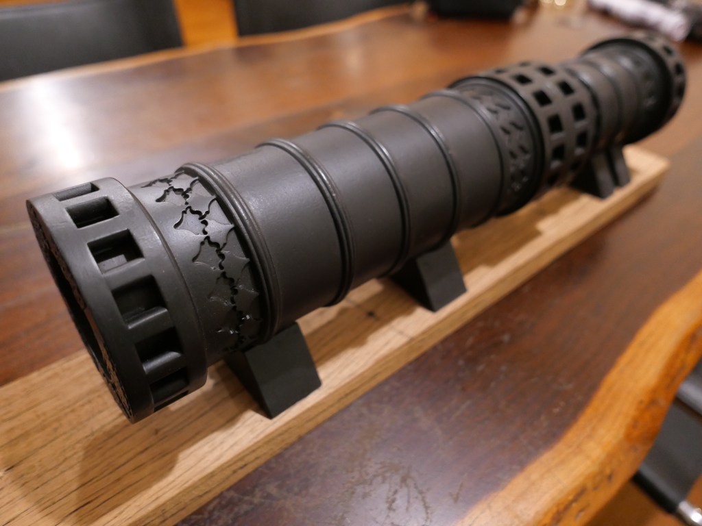
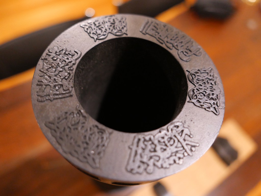
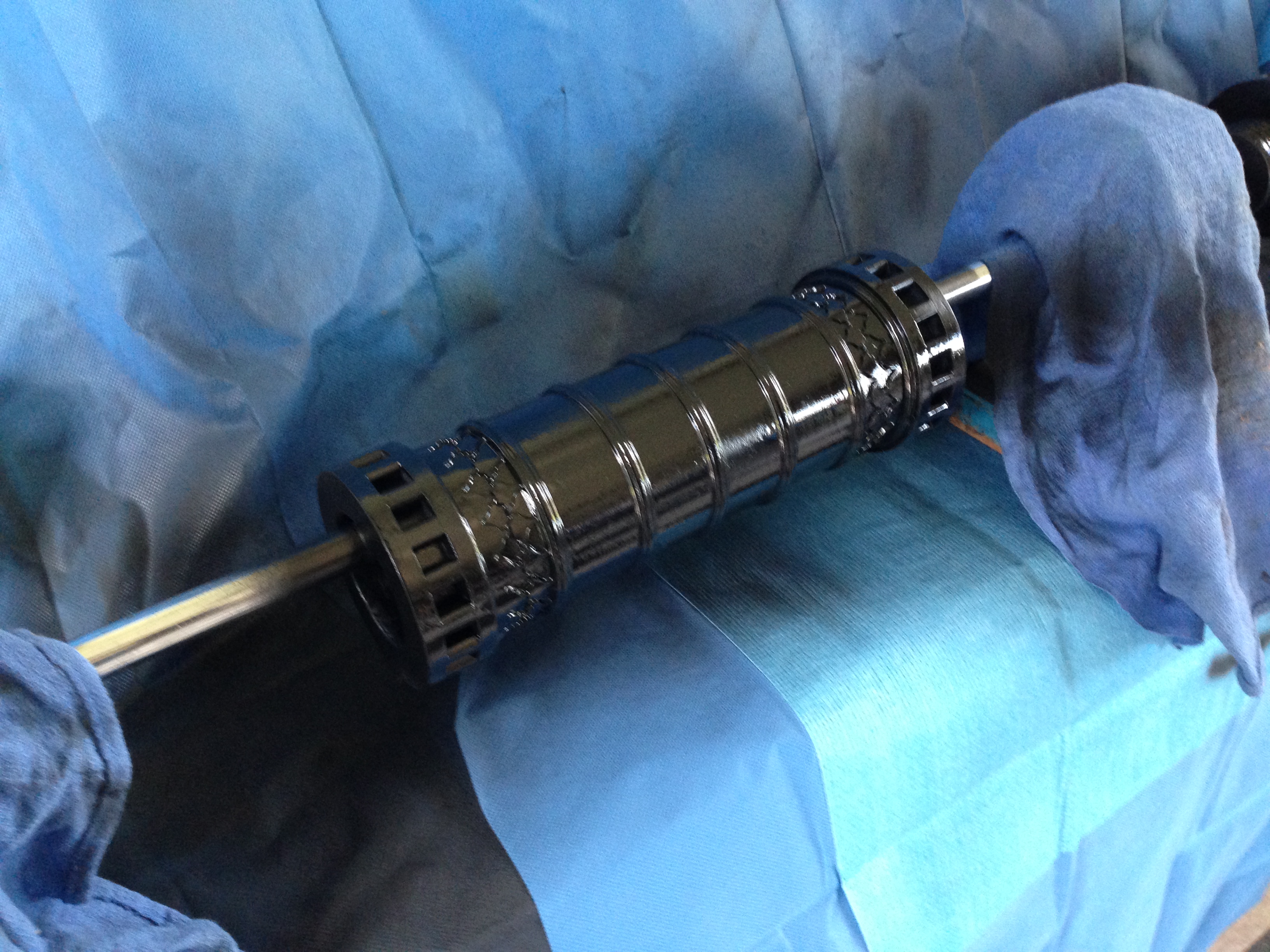
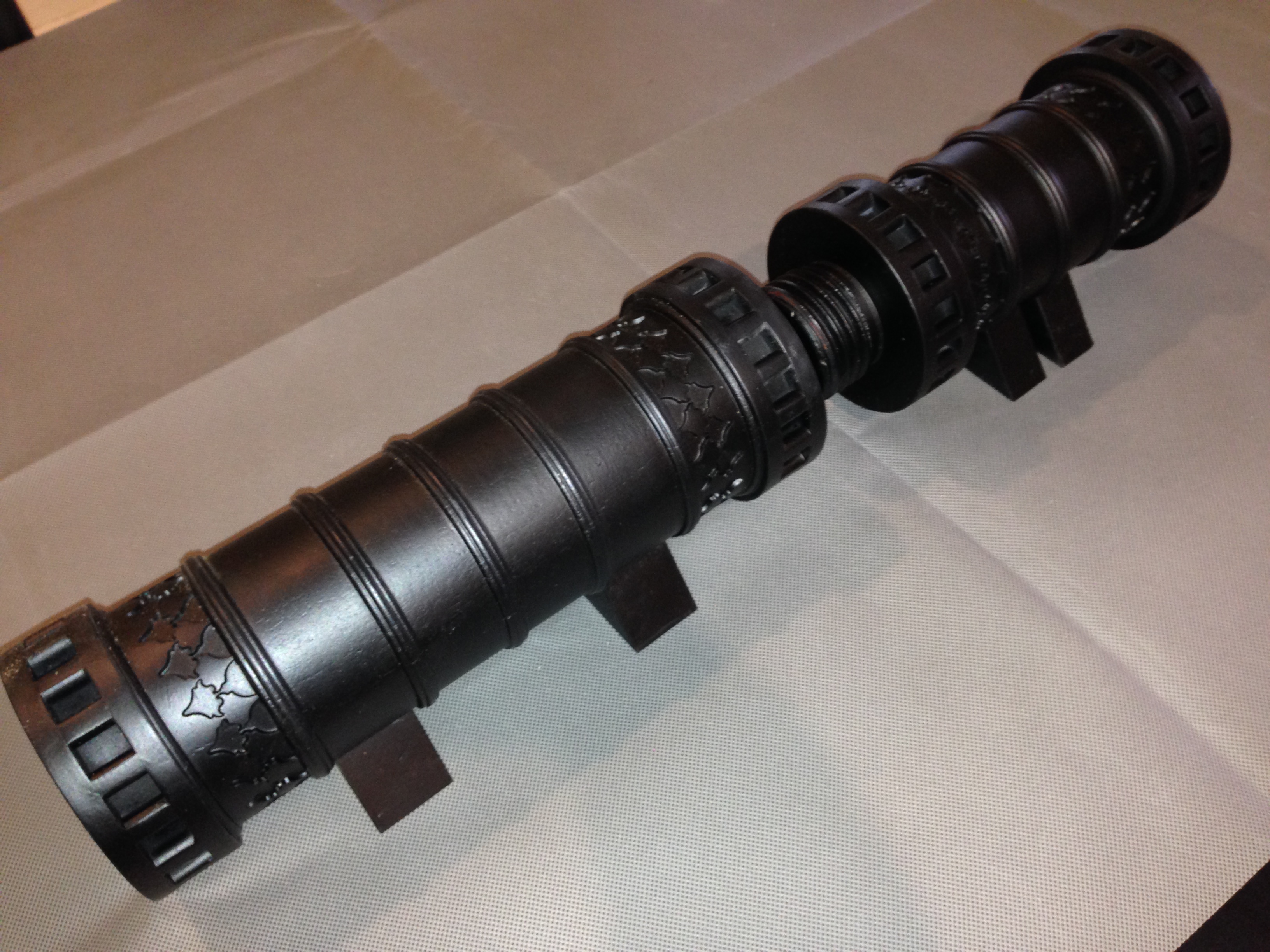
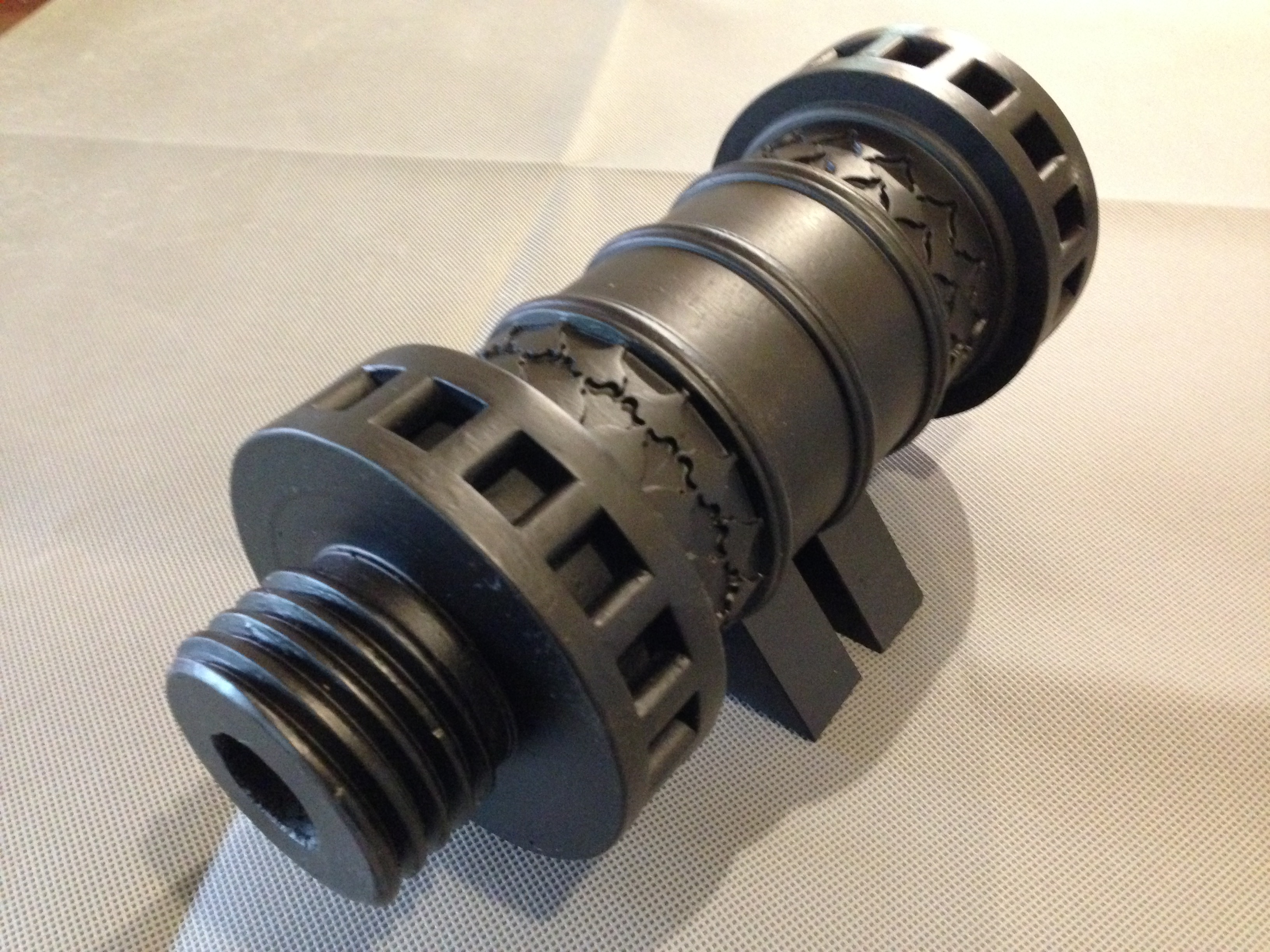
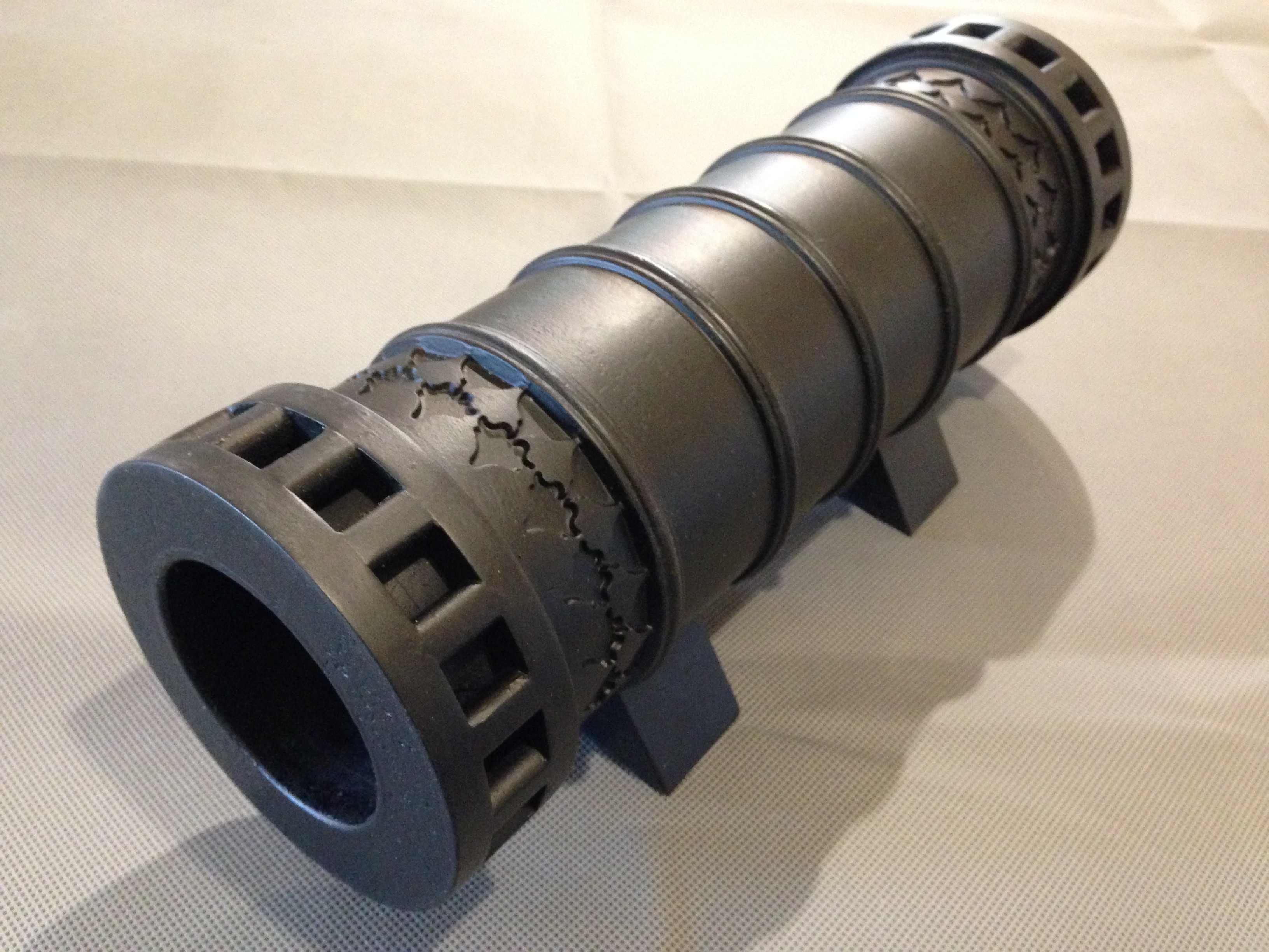
So I am contemplating making a model at the same 1:10 scale, like the original, in BRONZE. It will have the same shape and size, but will look like and feel like BRONZE.

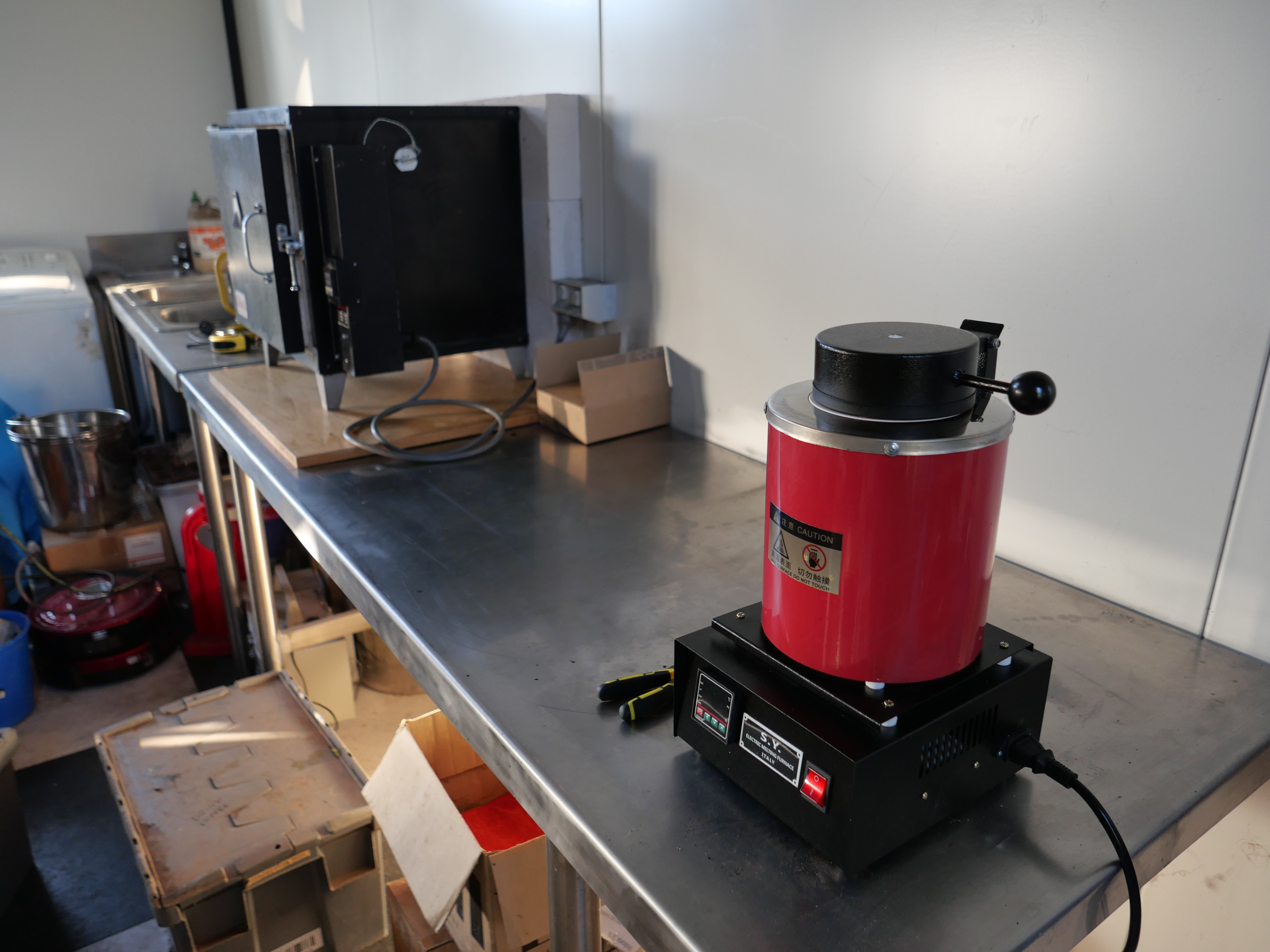
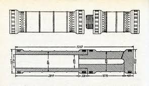
I still have my original measurements and drawings of the model. So my plan is to print the cannon parts in PLA, taking into account my extra information from the 2019 visit, then to cast it in BRONZE.

I had planned to stop this blog after finishing the Armstrong RML, but maybe , if there is enough interest, I will keep it going for the next project. You will need to let me know if this project will be of interest. Because lately, comments and likes are few, and numbers have been discouraging. And the renewal date for WordPress is approaching. I get it that people prefer videos, but that is not my style. If this written plus photographs style is not wanted then I will not persist.

TURKISH BOMBARD – a-post-script. And metal casting setup ready.

I made this 1:10 scale model of the Turkish Bombard which currently resides in the Royal Armories Museum, Portsmouth, in 2016.  I specify “currently” because I originally saw this cannon in 1979 at The Tower of London.  And long before that it was used in Turkey, guarding the Dardanelles.  Quite likely used in anger in 1805 against a British fleet, approximately 340 years after it was made for Sultan Mehmet “the conquerer”. 

And I re-visited the original in May 2019. It seems like half a lifetime ago. Mainly I visited the UK to see the Trevithick dredger engine in the London Science Museum, but the Turkish bombard was the second reason. I could not find a photograph of the touch-hole in the bombard anywhere. And my requests to the museum went unanswered.

The original bombard in the Royal Armories Museum, Portsmouth, UK.

So, here is my photograph of the touch hole, in case anyone else is inclined to make a model. I guarantee that this is the only photo of the touch hole which you will find, with my hand anyway.

The Turkish bombard touch hole
My 1:10 scale model of the bombard. I still have not added the touch hole.
The Arabic script around the muzzle. Not as good as in the original. But as good as I could manage in 2016.
and the large thread between the barrel segments


So, I made this model, in wood, as a practice run, intending to make a bronze model eventually.

The reason for this post script is that I had a question from a reader about a remark which I had made in 2016. And I could not find my original photographs. So I took some more, as you have seen.

And……… very excited to announce that I now have a foundry setup, and could possibly make a bronze example of the bombard. But first I intend to obtain some casting skills, by making parts for my 1:10 Armstrong cannon.

I replaced the analogue controller with a digital type in the potter’s oven which I had recently purchased, and today my wiring was checked by an expert before we ran a test run. (thanks Stuart!) All good, up to 750ºC, which is enough for preparing the investment molds.

Here is a shot of the oven, and the metal melting furnace.

PANA3860

from the right, the melting furnace which should be adequate for 3kg of brass/bronze,  and the investment oven. The oven might also be useful for metal tempering. Note the Hebel bricks behind the oven.

Hopefully, the first attempt at a casting session in a couple of days.


Turkish Bombard – the barrel mouth

IMG_4572.JPG

Except for a name plate I have finshed the bombard.  The floral design at 12, 4 and 8 is not as clear as I wished, and the Arabic script at 2, 6 and 10 is even worse.  But it is cut in wood, and it is a first effort at such work, and it is not easily seen in a model only 106mm 4.2″ diameter, so I am reasonably satisfied.

Also, this was always a prototype, in wood, and I have not totally dismissed the idea of making it in cast iron or brass.  In metal I am sure that the detail work would be a lot finer.

Turkish Bombard. The Barrel Script

Well, I bought a pair of NSK bearings for the Z axis of my CNC mill, and removed the old ones and inserted the new ones.  Cost $AUD 200.  Plus 2 or 3 half  days of  dirty heavy work.    And the problem persisted!!@!@

OK.  Time to get an expert opinion.  Here comes the cavalry.  Thank goodness for my expert friend Stuart T.

Very puzzling.  Even for Stuart.  There was some unwanted movement in the Z axis (about 2mm), despite being apparently properly installed.  Not a problem with the ballscrew or ballnut.  Even Stuart was puzzled.

“have you got any left over bits and pieces?  Is it all installed the way it was before?”

To cut the story short, we installed a thicker washer below the locknuts, and it seemed the problem was fixed.  Or was it?

Today I did another test run of the bombard mouth Arabic script.  Worked fine.  OK.  Time to finish the bombard.

IMG_4559.JPG

Here is the finished result, ready for painting.  I have used a 20 degree engraving carbide bit with a 0.2mm flat end.  There is some loss of fine detail but it is I think, adequate.  When it is painted, the filling putty above the pin screws (the white circles) will be invisible.  The engraving took a total of about 60 minutes, at 500mm/minute, 15,000 rpm.

IMG_4554.JPG

The setup.   A large angle plate clamped to the table.  The work clamped to the angle plate.

The translation of the Arabic script is “Help O God the Sultan Mehmet Khan son of Murad. The work of Munir Ali in the month of Rejeb. In the year 868.”

Turkish Bombard. The Arabic Script.

A little unfinished business on my model bombard is the Arabic script and floral decoration around the barrel mouth.

bombard-mouth

XIX.164 / 19-00164 Detail of muzzle of a great bronze gun. Turkish, dated 1464 Royal Armouries Museum, Leeds LS10 1LT Transparency tr-1185 Imacon Flextight Precision II

This is what I have managed so far….

IMG_4529.JPG

It is a practice run in scrap wood.

Some of the detail has disappeared because I used a milling cutter with an end width of 0.5mm.  Next time I will add another step using a cutter with a sharp point, and a lot more of the fine detail will appear.

That pattern took a total of 80 minutes to CNC mill, with the feed rate set at 500 mm/min.

Unfortunately my CNC mill developed a problem with the Z axis, probably due to a worn out end bearing.  I am hoping that it is not the ball screw nut.  Now in the process of removing the bearing. A heavy, awkward, dirty job.

When the mill is working again I will mill the actual bombard model and post some pics.

Computer graphics is not my strong point.  To get the CNC mill to cut that pattern I did the following..

IMG_4531.JPG

  1. Enlarged the photo, outlined the tracery and the script, then traced the outline onto tracing paper.  That 550 year old pattern is worn and hard to define in many places.  Quite a bit of guess work.  Lucky that almost no-one can read ancient Arabic script these days.
  2. Scanned the tracing and loaded the scan into Corel Draw
  3. Used Corel Draw to smooth the curves, and make 3 copies in an array of the floral design
  4. Converted the drawing to bitmap file (bmp)
  5. Used V Carve Pro to convert the bmp file to vectors
  6. Used V Carve Pro to generate the CNC G codes
  7. CNC milled the scrap wood at 16000rpm, using a 3.2mm carbide cutter

Model Ottoman Bombard – Painting

I would have preferred that the title of this blog was “Finishing the Ottoman Bombard”, but I am still waiting for the vectors of the barrel mouth decorations and Arabic (?) writing, and the touch hole.

But I have at least painted the bombard, and the pictures follow.  You will notice that I have not attempted to reproduce the bronze or copper colours of the orginal in Fort Nelson.  Partly because I doubted my ability to make painting such variegated patterns realistic, and partly because the cannon would not have looked like that in its heyday of 1464.  It would probably have been either black, like most SBML cannons (smooth bore muzzle loading), or possibly gaudy golds and reds and blues like other medieval items.  So I painted it black.  I like it.  If I get evidence that it should be more colourful I can change it later.

IMG_4429.JPG

First coat – Primer.  Hmmm… interesting colour.

IMG_4434.JPG

Next coat – matt black brushed on, to fill the hairline wood cracks.  Incidentally, the (dirty) parquetry floor is also made from the red gum house stumps from which the cannon is made.

IMG_4447.JPG

final two coats –  matt black, from a spray can. 

IMG_4458.JPG

So there it is, finished except for the barrel mouth engraving, and the touch hole.  Now what to do with it…   SWMBO says it might be useful as an umbrella stand.

IMG_4460.JPG

The breech.  25mm diameter explosion chamber.  1:10 scale

IMG_4461.JPG

The barrel, 63mm bore.

IMG_4462.JPG

Assembled.  The model is 520mm long.

IMG_4464.JPG

It does need some decoration

turkish-bombard-plan

TURKISH BOMBARD- HELP!

Does anyone have a decent photograph of the writing on the muzzle?

I have repeatedly hunted through every picture which I can find on the net, but they are either taken at an angle, or too poor quality to be useable.

Does anyone have a photograph which I could beg buy or borrow?

I also need a photo of the touch hole.

I have contacted the Fort Nelson Armoury Museum, but not too surprisingly there was no response.

Is there someone in the Portsmouth UK area who could pop in and take some pics for me?

POSTSCRIPT:  October 5.   I have had 2 excellent and positive responses to my appeal.

First, reader Richard sent me a connection to a Turkish Dr/Professor, who has made a 1:25 model of the bombard using 3D printing.  (at least that is how I think he has done it.  My Turkish is non existent).  I am following this lead.

Secondly I have had a response from Fort Nelson Armoury, with a good photo of the barrel mouth, and a high res photo on the way, after payment of a significant, but not unreasonable fee.  Isn’t the Internet wonderful!!


TURKISH BOMBARD – the real thing

I have found this video to be particularly useful in my modelling of the Ottoman bombard. The subject of this video is the gun that the Turkish sultan gifted to Queen Victoria when the Brits and the Turks were allies.  It might be one of the guns which fired on the British fleet in 1807, when it (the gun) was 343 years old!

Notice the colour.  It is aged bronze.  I am thinking about how to reproduce that colour on my model.


Length of the assembled gun 5.2m (17′)

Bore 635mm

Breech weight 8942kg

Barrel weight 8128kg

Average weight of shot 307kg

the model is at a scale of 1:10.  photos soon.  being painted.


Modelling A Turkish Bombard- The Pins

b281d1ba4455df20d7b832411bb00443

There are 16 pins at each end of each section of the cannon.

These were certainly used as leverage points, for very strong men with large levers to rotate the 8-9  tonne segments against each other to engage and tighten the screw.

I cannot see how the pins would have been cast with the breech and barrel.  For my model I decided to make separate pins and fit them into the gap between the big rings, then insert a grub screw through both rings and the pin.  The holes are then filled.

I wonder if a similar method was used in 1464.  I would love to have a close look at the original cannon to figure this out.  From the photographs, I can see no evidence of later insertion of pins, but neither can I see how it would have been done any other way.

IMG_4373.JPG

Drilling the holes for the grub screws

IMG_4395.JPG

In order to continue with red gum, I made my own pins.  This is the setup.  The blank is held approximately centre in a 4 jaw….

IMG_4396.JPG

…and the pins are turned, centre drilled, drilled, cut to length,  and tapped M4.  64 altogether.

IMG_4421.JPG

The M4 x 25mm grubscrew is screwed into the pin.  The wood join is super glued.  Also, I am attempting to patch the worst of the thread tearouts.

IMG_4423.JPG

Using a battery screwdriver to insert the grub screws.  The pins protrude above the ring surface for a reason..


IMG_4424.JPG

Sanding the pins flush with the rings.  Check the photo of the original 1464 model.  There is also some wood filler in other splits.  Not surprising after holding up a house for 70 years.

The holes are now filled with wood filler, and will be sanded flush.  They should be invisible after painting.

Next the painting, the stands, and some cannon balls.  How to reproduce that aged copper colour…


Modelling a Turkish Bombard -4 Decoration

The decoration around the barrel is formed by a repeating pattern, which when milled, very cleverly forms 2 identical patterns.  One is excavated and one is the original barrel surface.  You will see what I mean if you look at the pictures in the earlier blog, and the video below.

It took me an evening of experimenting on the computer to work out the system and draw it.

bombard-pattern3

Then I measured the diameters of the 2 gun components, calculated the circumference, (OK it is not rocket science.   3.142 times diameter), then working out the number of identical shapes which would fit around the 2 different diameters, at the same size and spacing.   Amazingly, it took 18 shapes to fit almost exactly around the barrel, and 16 of identical size almost exactly around the breech.  the angular spacing was 20 degrees and 22.5 degrees.

Then the shape was imported into V-Carve Pro, and G codes were generated.

My CNC mill does not have a 4th axis, so I used a dividing head to move the workpiece at the precise angles.  See the setup in the video.  That meant that the pattern was engraved into 16 and 18 flat surfaces, rather than a continuous cylinder as on the original.

It worked very well.  There were minor compromises due to the shapes being milled with a fine end mill but when you look at the pics I hope that you will agree that it is effective.

I calculated that the milling had to be at a maximum depth of 2mm in order to cope with the curvature, but if I do it again,  I would reduce the depth by 25%.

The first part of the video is a shot of CNC drilling.  Then the CNC routing of the repeating patterns.  Each angular setting of the pattern took 4 minutes to complete.  136 minutes altogether.  In reality, it took a whole day, most of which was spent doing the setups.


Bombard Model-3 turning the barrel

Another session or two, and this project is complete.

Now how do I make a cannon ball 62-63 mm diameter?  In wood will be ok?  Does not have to be granite.  I could make a mould and cast it in aluminium or lead, but stone would be authentic…..   thinking.

ps.  Re cannon balls.  I will cast them, in cement!   Now, how to make a mould.

Bombard Model -2. Big Thread

The breech and the barrel are joined with a very large thread.  On my 1:10 scale model it is 60mm diameter, and has a pitch of 6 mm.  These dimensions are measured off Internet photos of the original bombard, so they might not be faithfully accurate to the original bombard.  If anyone has accurate plans of the bombard I would be very interested to hear from them.

I experimented with various spindle speeds, feed rates, depth of cut, and finally decided that red gum wood is not the ideal material to be cutting a thread with sharp points.  However, at 200rpm, and taking 50 cuts to reach the full depth, and using a very sharp tool, the end result was OK.  I will fill the tearouts.

In order to make a functional join in the wooden cannon, I truncated the apex of the thread.  In the gunmetal version I will attempt a more faithful to the original, sharp look.

For some reason, the wood held together better during the internal thread cutting than the external.


The male thread was cut on my newly CNC converted lathe,  between centres, but the fixed steady on that lathe was just too small to hold the barrel, so the internal thread was cut on my bigger Chinese lathe.

Next I will bore the barrel to 63mm, then turn the exterior of the barrel.


Bombard Model. Turning the Breech


So if you watched the video, you can see that I have a problem with the big thread between the breech and the barrel, at least in the wooden prototype.  It might work better in brass or gunmetal.

The thread has a pitch of 6mm and a diameter of 60mm.   It is big.

My plan at this time, is to make a brass male threaded section, and glue or screw it into the breech.  Then to make a steel tap using the same G code, and cut a thread into the wood of the barrel.  (p.s.  note 30 Sep…  I continued to experiment with feeds, speeds, and cutter shapes in the wood.  The final result was OK so I did not make  metal threads.  That will have to wait until I do this project entirely in gunmetal or brass…  maybe never)

Turkish Bombard 1:10 scale

Just for fun I will use my newly converted CNC lathe to make a 1:10 bombard.  The original was cast in 1464 and was thought to be a close copy of the bombards which Mehmet 2 (“the conqueror”) used to breach the walls of Constantinople in 1453.  There are several of these bombards still in existence, including one in UK, which was given to Queen Victoria by the then Turkish Sultan.

These bombards were last used, against the British, in 1807, when a British warship was holed with substantial loss of life.  Pretty amazing for a 340 year old weapon.

images

5.2 meters long, 1.060 meter diameter. 16.8 tonnes.

b281d1ba4455df20d7b832411bb00443

The large thread connected the halves.  Easier transportation, and casting.


images

Is this Turkish or Arabic?

images

Granite balls are 630mm diameter.


tembokkotakonstantinopel

A reconstruction of the walls of Constantinople, with moat.  Almost 1000 years old in 1453  

walls-of-constantinople

And as they are today.  Massive.  High.

29962555-Huge-siege-the-final-assault-and-fall-of-Constantinople.jpg

Huge siege cannon used in the final assault and fall of Constantinople in 1453. Diorama in Askeri Museum, Istanbul, Turkey.  The bombards were probably dug in, to manage the massive recoil, and concentrate the aim at a particular wall section.  There is a wooden structure built around the cannon in the background of this modern picture.  As far as I know there are no surviving  wooden structures like this.  Nor have I come across any old pictures, but if anyone knows of any I would be very interested.  The bombards took about 3 hours to cool, cleanout and reload.  

p1090990.jpg

My model will be about 520mm long.  I would like to make it from bronze, or gunmetal as in the original.  Any mistakes will be costly.

So I have decided to make a prototype in wood.  That will test my drawing, the machining procedure, and the final appearance.  Not to mention how the CNC lathe will handle the task.

I will use a very dense, tight grained Australian hardwood (red gum).  The wood was salvaged when my house stumps were replaced with concrete.  Some was used to make parquetry, and the rest was put aside for possible future use.  Such as this.

IMG_4313.JPG

About to cut off the below ground section of a 70 year old house stump.

IMG_4320.JPG

A 5hp metal lathe with a tungsten bit chomps through the hard dry wood.

IMG_4322.JPG

I turned 6 lengths before I found 2 that were satisfactory.  The rest had sap holes or splits.

I have used Ezilathe to generate the G codes.

to be continued….