
Trevithick Dredger Engine. What was the original design?
by John
As I am progressing with building the 1:8 model of the dredger engine, I am experiencing doubts about the authenticity of the design by Tubal Cain 1985, and redrawn by Julius DeWaal 2016. Those plans are based on the engine in the London Science Museum, which we know was incomplete when found in a scrap yard (?) and reconstructed in 1886. There are no known or published original plans.
Look at the following photographs. The first two are boiler components labelled as Trevithick, although incomplete, appear to be unmodified.
The following drawing comes from Rees’s Cyclopaedia, published first in 1819, when many of the engines would have been operating, and given the quality of the drawing, is likely to be fairly accurate.
Finally, the engine in the London Science Museum, which shows some Victorian era features which are highly unlikely to be as Trevithick designed them.

The firebox and firetube, riveted to the end plate. Note the inspection hatch has no rivet or bolt holes. How would the hatch have been attached?

Showing the end plate bolted to the cast iron boiler shell. Interestingly, the penetrations are mirror image of the LSM engine. Does anyone know where this boiler is currently located? And why are there no rivet or bolt holes around the inspection opening?
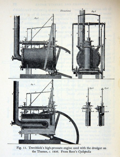
Drawing from circa 1819. Note 1. the wooden support at the chimney end of the boiler, 2. the flange for the chimney attaches directly to the end plate, as does the inspection hatch and the firebox door. None of these protrude beyond the end plate.
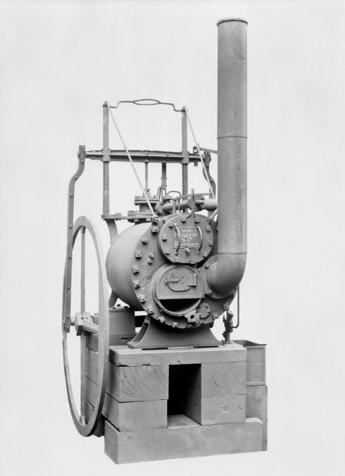
This is the best photograph I know of from the reconstructed LSM engine. There are multiple inconsistencies with the Rees drawings…
The inconsistencies which I note are:
- The support under the flat end is metal, not wood. It is cast or fabricated, and curved. Unlikely to be original.
- The rear support in the Rees drawing is metal which sits on wooden bearers. Quite different shape from the Cain/deWaal plans.
- Some of the flywheel spokes have a moulding, some are plain. I imagine that plain is more likely original.
- The connecting rods are bent at the top. They are straight in the Rees drawing.
- There are no rivets or rivet holes around the firebox. There appears to be a new cylindrical insert into the firebox. Unfortunately the Rees drawings do not show the firebox. The firedoor hinges appear to be welded in position. There are holes in the firedoor which could have been used for strap hinges, which would be more likely in use originally. There is no provision for air intake control. I wonder if Trevithick would have provided an adjustable flap? I am told that some early Cornish boilers did not have any flap.
- The inspection hatch looks realistic. But the hatch sits away from the end plate, presumably to permit access for the end plate to flange bolts. Would Trevithick, I wonder, have designed such a complex setup? Bearing in mind that every piece of iron or steel must be shaped in a forge by a blacksmith, then riveted or bolted into position, or cast iron, then bolted into position. The rather irregular position and shape of the inspection plate and bolts looks authentic, but I have my doubts about whether the inspection hole itself is authentic. Could this have been cut out later, when boiler repairs were required?
I have not looked closely at the engine details. No doubt further inconsistencies will be apparent there.
So I am in a bit of a quandry. Do I make the Cain/deWaal model, removing the obvious inconsistent features but including the dubious ones? Or do I guess at what Trevithick would have designed, based on the technology which he had available?
Any opinions or thoughts/advice would be welcome.

John, boiling it down (no pun intended), I think ” the dubious ones” are where, in my opinion, your best guess would be a pretty valid way to plan things.
If you then think thought through the various elements in the light of your research, I think a picture of the whole will emerge which will be either more or less convincing helping you decide.
If it’s more convincing you can do no more and can go ahead integrity in tact.
I remember one of my old professors coining the maxim: ” Heresy with integrity pleases the Lord”
I’d go with your gut in the end.
Cheers, Tim
LikeLike
That is very reassuring Tim, on several levels. Thank you. And my gut thanks you.
LikeLike