johnsmachines

machines which I have made, am making, or intend to make, and some other stuff. If you find this site interesting, please leave a comment. I read every comment and respond to most. n.b. There is a list of my first 800 posts in my post of 17 June 2021, titled "800 Posts"

Category: Trevithic Dredger Engine

Melbourne Society of Model and Experimental Engineers. Xmas meeting.

The December meeting includes the competition for best model, best workshop tooling, and best engine.  The 3 happy winners were all from Geelong.

78947095_10218922337503859_5458110964505247744_o

Stuart Tankard, John Viggers, Swen Pettig

79025950_2448598021904988_6639730611655278592_o

Trevithick dredger engine model by John

78899194_2448597938571663_1550976217446875136_o.jpg

79084789_2448598095238314_3887537897913450496_o

CNC lathe tools, toolholders and toolpost milling attachment by Stuart.

Following is a video of Stuart’s toolpost milling attachment in action.  It has been posted before, but is worth watching again.  It is quite remarkable.

(Photo of the flame gulper to be added.)

But, the best part of the meeting was this demo of a model aeroplane which was made by Don.  The plane weighs 2.5 grams!!!   The wing material is mylar which is 1 micron thick!!!  The flight was cut short by hitting a ceiling projector, but apparently the world record for a flight by a similar plane lasted for over an hour!  This YouTube video has had 360,000+ views in 5 days!


Bad Paint Job

As I reported on Sep 3, I was recovering from a decent dose of influenza, and feeling a need to do something after almost 2 weeks of inactivity, and I decided to put some more paint on the Trevithick dredger engine.  After all, what could go wrong?   Just a bit of gentle painting.

I was quite proud of the job.  No paint spills.  No brush marks on neighbouring items.  No brush hairs in the work, and minimal brush marks.

I wondered how long I would need to wait between coats, so I checked the paint tin.

O shit!   I had used the wrong paint….

IMG_8170

I had used the epoxy enamel instead of the high temperature resistant Pot Belly Black!  The brain had apparently not recovered fully from the ‘flu.

I decided to sleep on the problem.  Checked with my resident paint expert (SWMBO), and on her suggestion, next day applied some mineral turpentine.  The paint was dry, but the turps did seem to soften it.  So I applied some more turps, then attacked the epoxy paint with a rag.

To my delight, it mostly came off.  I was not too bothered by the paint in the deep cracks…. that could be a filler.

Then I carefully dried everything, another rub with clean rags, and applied another coat.  This time using the correct paint.  2 coats.

Reader Huib asked how it had all eventuated, so today I took some pics of the engine in its current home…  our kitchen.  The budgerigars are SWMBO’s decorative touch.

Trevithick in kitchen.jpg

The kitchen is due for a renovation.  I made those cupboards and benches 30 years ago.

Trevithick in kitchen close.jpg

But the paint job looks ok hey?

P1032904.JPG

Another view.  In the background is a painting of a dog training group in the grounds of the MCG, by Samantha Lord.

Hey readers (male and female), waiting for more workshop photos to post.  It doesn’t have to be the whole workshop…. just a photo of your favourite machine would be great!

Fit after 9 day influenza?

Today is the first day since I became sick that I have felt able to drive.  Until today I have been experiencing coughing paroxysms, severe headaches, dizzy episodes, even 2 episodes of hallucinations which were really weird.  Also requiring pain killers regularly.

My GP thinks that I have had influenza A, despite vaccination earlier in the year.  Certainly the nastiest bug which I have encountered in many years.

But as today warmed up, and I had not required any analgesics, and the coughing was settling, I decided to visit my workshop.   “Visit”, rather than operate machines.  I suspected that my mental faculties were not yet 100%.   It is a 20-25″ drive to my workshop, so off I went.

I was pleased to note that my neighbour had mowed the grass around my sheds.  It had become quite thick and high, and with the warmer spring weather today, I was not looking forward to walking through the thigh high vegetation which could conceal nasty poisonous fauna.  The neighbour has long term loan of my tractor and slasher, and the quid pro quo is that I get my grass mowed whenever required.

So what to do, not requiring turning on potentially dangerous machines?  I decided to look at the Trevithick dredger engine.  It has been waiting for some painting.  That would not be too arduous or too dangerous!

The engine end of the boiler was waiting for some flat black paint.  So I removed some appendages, filed and wire brushed the surfaces, and washed them down with mineral turps.  Found the paint, stirred it thoroughly, and carefully applied it with some small, new brushes.

IMG_8167.JPG

The engine end of the machine, with one coat of the flat black applied.  Hmm…. I don’t remember it going streaky like that before…..   Maybe the second coat will look better.

I used the paint to touch up some other areas also.

Then as I was cleaning up, before going home I took another look at the paint can.

O shit!  I had used the wrong paint can!

img_8170.jpg

I should have used the “Pot Belly Black”.  Somehow, I picked up the other one.  The “Rust Guard Epoxy Enamel” is good paint, but it might not tolerate the surface temperatures of the boiler.   And an etch primer is recommended for it, which would explain my application problem.

So what to do?   I know that most of you will be screaming at the screen, to strip off the epoxy paint and start again.  But, for better or for worse I have decided to apply another coat of epoxy tomorrow and see if the appearance improves.  I expect that it will.  Then a trial firing in a few days will demonstrate whether the epoxy will cope with the temperatures.  If it copes…. fine.  It is well away from the furnace.   If not, then a very time consuming strip job and repainting will be in order.

It seems that my mentation has not fully recovered.

Back to the Trevithick Dredger Engine Model – the lagging.

The only surviving Trevithick dredger engine, in the London Science Museum, shows no signs of ever having been lagged.  I know this, because I examined it closely, recently, during my UK trip.

No lagging, no marks in the paintwork, which would indicate wooden lagging strips ever having been attached.

But, we know that Trevithick readily adopted ANY improvements to his designs, and lagging was appearing on engines at about the epoch of the dredger engine design. Plus, his engines were in use as late as mid 19th century, and lagging was well established as a normal feature by that time.

And, my model definitely needs some efficiency improvement.  Using a 40kW burner to power an engine of this size is ridiculous.   So I Have added some lagging.

P1032772.JPG

Equipment for applying lagging, from the left…   scroll saw, super glue (I used 6 tubes), strips of wood (in this case, Australian Jarrah, grinder for shaping, Dremel for shaping, good light, and the engine with some of the strips glued in place.

I used about 48 strips of wood with some spares.  These were cut and sanded in advance.  5mm x12mm x 130mm.

The Super glue is used to hold the wood strips in place temporarily, until the brass boiler bands are installed.

I started at the top, and worked my way down on both sides.  Most effort is made in fitting around  pipes and boiler bosses.  Unsatisfactory strips are levered off and scrapped.

P1032773.JPG

A rebate was milled on every wood strip, to permit removal or tightening of the boiler end plate nuts.

P1032774.JPG

I used rubber tree ties to maintain pressure until the glue dried, but in most cases I just applied finger pressure until the wood stuck fast.

P1032775.JPG

Some pipes and fittings necessitated grooves being made with round files.

Super glue does not provide a permanent bond to copper for some reason.  And it certainly will not survive the heat from steaming.  But it is fine for a quick and temporary bond.

P1032776.JPG

After making and applying the brass boiler bands (this was covered in the “6”vertical boiler” posts) I used olive oil to seal the wood.  See discussion which follows.

I chose olive oil to seal the grain openings of the jarrah.  I know from previous firings that the temperature of the boiler shell does not exceed 100ºc.  Olive oil will not smoke or flame until the temperature exceeds  200ºc, which is higher than any other common oil.  Also, as a failed olive farmer, I have plenty of old olive oil.   At worst, my engine steamings might smell like a fish and chip shop.  And refreshing the oily surface will be quick, cheap and easy.  And the olive oil will not form a skin which might peel or flake.  Anyway, this is “model and experimental” engineering.  If it does not work, I will make some new lagging, alright!.

And I took some more photos with my Panasonic Lumix 100-2 camera…….

P1032781.JPG

Still some more painting required to the end plate, and some fittings.

P1032808.JPG

That domed boiler end with the cylinder protrusion also needs some paint.  But the lagging looks good hey?

Even SWMBO has relented…  “It can go with the other engines”.  It will, when it is finished.  Still requires more painting.

First Steam Locomotive.

In 1802 a Richard Trevithick designed engine was made by the Coalbrookdale company.  Not much is known about it, but is recorded that the steam pressure reached 145psi!  Trevithick had previously operated his road steam locomotive up the Camborne Hill, but this was the first one to run on rails.

The next one was made for the steelworks at Merthyr Tidfil, Wales.  It was a Trevithick engine which ran on rails.  The owner made a 500 guinea bet with a rival (an astronomical figure.  Somewhere I read that it would be equivalent to a million dollars these days), and in Feb 1803 the engine towed 5 wagons, loaded with 10 tons of iron ore (or coal, not sure), and 70 odd bods, a distance of 10 miles.  There was dispute about whether the bet had been won due to some technicalities, and no record of it being paid, but it was a moral victory.  The age of steam had really begun.

The biggest problem was not the locomotive, but the rails.  They were not strong enough, and frequently broke.  It took the genius of George Stephenson to solve that problem, by using forged iron in preference to cast iron.  And his son Robert to increase the efficiency of the engine and boiler in the form of “Rocket”.  But that is another story, for 30 years later.

Unfortunately the original of the Merthyr Tidfil loco has not survived, but several replicas have been made, based on original drawings.  I saw one of them at Swansea, Wales, not far from Merthyr Tidfil.  Not a steaming day.  It does run.

P1021619.JPG

Not great photos.  The lighting conditions in the National Waterfront Museum were difficult.

P1021605.JPG

The typical big, skinny Trevithick flywheel, and driver’s wagon.

P1021607.JPG

Square main shaft.  Hex nuts were not around in 1802.  

P1021629.JPG

And that is a view that you don’t often see.  The pressure gauge is definitely a modern requirement, as I discovered with my dredger engine.

P1021625.JPG

Notice the fish belly rails.  Originals were cast iron.  “Fish belly” shape to increase the strength, but alas, not strong enough.  Hex nuts again!  And those gears have modern shaped teeth.  Quite a few compromises in this replica.

And I have now arrived in Camborne, Cornwall, Trevithick’s home, and the site of his famous trial of the steam road loco.

I made a pilgrimage to Fore St (“Camborne hill”), then to his statue, to pay homage.

P1021728.JPG

Richard Trevithick.  Genius.


Trevithick Dredger Engine at The London Science Museum

I landed at Heathrow at 6am, dropped my bags at the BNB, then caught 2 buses to the Science Museum.  Not jet lagged, but on a high, to see the only intact Trevithick Dredger Engine known to exist.

The room which houses the Trevithick, also contains 4 large beam engines, a Parson’s turbine (of “Turbinia” fame), and a very large 2 cylinder compound.

Disconcertingly, the first atmospheric beam engine, with wooden beam, was partly obscured by a souvenir stall and racks of clothes for sale.  WTF!   Don’t they realise the historical importance and rarity of these engines.  And 3 further moans, to get them out of the way.   The descriptive labels on all items had minimal information.  Nothing like dimensions, power, etc.  The attendants knew virtually nothing about the engines.  And often, items were behind glass or perspex which was reflective, and prevented good visualisation or photography.   To be fair entrance was free, but to get past the entrance desk it seemed pretty clear that a “donation” of 5 pounds was expected, (which I was happy to contribute).   Those complaints aside, I have to say that the collections were fabulous.

I could see the Trevithick at the far end of the room, so to curb my mounting excitement, I forced myself to not rush up to it, but to try to look at every exhibit on the way.

Eventually I was there and it was there in front of me.

P1010346.JPG

It was one of the smallest engines in the room (The “Energy” hall).  The older beam engines were many times larger, but that was a major reason this engine was so successful..  more power, lighter, smaller, and several times more efficient at converting coal to rotative motion.  No one could tell me why there is a huge divot in the cast end of the boiler.

The con rods, stands, standard cross tie, and chimney are not original, but were added when the engine was restored in ~1875.  But that is now part of its history.

P1010330.JPG

P1010339.JPG

P1010341.JPG

From that side it was apparent that the main shaft was square over its entire length, something not previously known to me.

P1010335.JPG

The boiler feed pump was relatively tiny.  I do not know if it is original.

P1010331.JPG

The firebox has been re-sleeved.  The chimney mount is part of the end plate casting.  And I think that I got most of these items pretty close to right on my model.  Does anyone know what the incomplete flange at 5 0’clock would have been for?

P1010332.JPG

Note the odd bolt pattern around the inspection hatch.  I got that wrong.  My change to the oblique slide rod stay angle brackets was correct.

P1010333.JPG

safety valve weight is adjustable.

P1010338.JPG

Water preheater pipe detail.  Aren’t the square nuts great!

P1010350.JPG

The throttle restraints are curved, and have fixed position holes for pins.

P1010336.JPG

Boiler feed tank.  Cast iron.

P1010356.JPG

Engine supports appear to be cast integrally with the boiler.

P1010354.JPG

Flywheel hub

P1010362.JPG

Flywheel spoke detail.  Likely original.

P1010370.JPG

Chimney mount detail

P1010462.JPG

Finally (although I do have more photos), a nice view from above.  I do like the crosshead shape.  I wonder if it is original.  Remnants of another Trevithick dredger engine  not currently on display, reveal a wooden crosshead beam.

So there you are.  Fascinating to me.  Interesting enough I hope to you.  I could see no evidence of wooden lagging at all, but i still intend to install some on my model to slightly improve its efficiency.

i have heaps more photos of other exhibits which I may post later.


OZ to UK

Well, I am off to Blighty tomorrow, to check out the originals of some of the models which I have made in recent years, and to pay homage to Richard Trevithick.

First stop London.  And the first stop in London is the Science Museum, where I will head straight for the Trevithick Dredger Engine.  This particular engine was made in 1806, but was designed by Trevithick several years earlier.  It was used to power a dredger on the River Thames.  Later the design was used to make steam engines to power the mills and factories of industrial England.  About 600 were made altogether, but this is the only surviving intact example, having been found in ~1878, and restored, albeit with some non authentic features.

I am due to arrive at Heathrow at 6am, and I cannot book into my accomodation until 2pm, so I will front up at the museum and put my case into storage while I spend some happy hours with the Trevithick, and browsing some of the rest of the museum.  I believe that the museum also houses a model of the road steam vehicle, which was built by a clockmaker for Trevithick as a proof of concept model.

So my next post here will hopefully include some photos of the above.    It is planned that this will all follow a 22 hour flight from Oz, via Singapore.  Not sure what shape I will be in, but hopefully I will have something to show you.

The next few days in London are planned to include The London Water and Steam Museum at Kewbridge, the pumping station at Kempton, The Crossness Engine at Abbey Wood, HMS Belfast, and maybe a return visit to pay my respects to the Harrison Clocks at Greenwich.  Busy busy!

Then a 4+ hour drive to York.  If I leave early enough I should reach York with enough time to visit the viking museum, and maybe even fit in a visit to the glorious minster.

The next day is scheduled for the National Railway Museum, which I have never seen before, and has been recommended by many bloggers.  And I will be meeting a reader of this blog, who will be showing me around the rail museum, and other interesting sites around York.

And so on.

I hope to be able to post some photos as I progress, but that will depend on Internet connections at my booked accomodations.  All Air BNB.

Later stops will include Manchester, Coventry, Leicester, Swansea, Merthyr Tydfil, Camborne, Dartmouth, Portsmouth.  Each place has been chosen so I can see outstanding museums, engines, mines, historic ships and places significant for Richard Trevithick.

The final stop at Portsmouth was mainly to visit the Fort Nelson Museum so I can see the Dardanelles Cannon close up.  But I will not miss the opportunity to see the Henry 8’s Mary Rose, HMS Victory, HMS Warrior, the submarine museum  etc etc.    Ben L, I will be in Portsmouth Tues 28 May pm until Fri 31 am if you are able to meet, perhaps one evening?

If you are getting the impression that I am very excited about this trip, you are absolutely correct!     John.


A Fraternal Photo

IMG_6836

Me and my brother Peter.  No doubting the genes.

My brother also makes steam engines, but he prefers the ones which move on steel rails. Unfortunately he lives a long way away, in the deep north of Australia, so we see him and his wife only once a year or so.

Trevithick Engine by Lumix, and an Ottoman cannon.

Some more photos with the Panasonic Lumix LX100M2.

P1010115.JPG

The Trevithick dredger engine, still lacking lagging and paint.  The chimney has a chimney extension connector, sitting a bit crooked.

P1010119.JPG

I am very impressed by the quality of these photos.

And some shots of the 1:10 model Ottoman Dardanelles cannon, which I made a few years ago.  It was intended as a practice run in wood, before making it in bronze.  The wooden model is 600mm (2′) long, and since finishing it I have not felt the need to make a bronze example.  I plan to visit the original at Fort Nelson, Portsmouth, in a few weeks. Watch out for a video/photographs on johnsmachines.com

P1010107.JPG

P1010102.JPG

P1010112.JPG

P1010109.JPG

I think that you will agree that the quality of these photos is excellent.  The photographer is still learning.

Sir Ding Dong.

Not much happening in the workshop.  Visited by my middle daughter and family this weekend.

The boys are now 3, and responsive enough to not touch hot or moving parts and to watch out for wriggly pets.  I have seen 3 so far this season.

So we decided to give the boys some exposure to live steam.  They were intrigued by lighting the fire in the boiler, then adding wood and coal, and building up steam.  Nervously then enthusiastically operating the whistle.

Then the fun bit.

56331017_10155878660711901_6634981610481516544_o.jpg

Sir Ding Dong is a 3″ scale 2 cylinder compound steam traction engine.  It will tow this load easily.

We have had virtually no autumn rain yet, and the ground cover is very dry.  But it was a sunny and windless day, so it seemed safe enough to operate the steam engine.  No problems.  The kids, aged 3 to 69, loved it.


Oh, and by the way, the Trevithick dredger engine boiler passed its final inspection!  WooHoo!


Video of the gas burner which works

The first 6 minutes of the video  is getting up to 40psi.  Then a couple of minutes of the engine working.   Big file, so be patient.

At Last, a burner which does the job!

You are probably fed up with my burner trials.  I certainly was.

Fundamentally, I was trying to get enough heat into the Trevithick model dredger engine boiler, and just not managing it.  My boiler is a scaled down version of the original, in copper.  It takes a lot more heat than the 6″ vertical boiler which I made last year and I think that the reasons are…

  1.  The Trevithick design, although revolutionary for 1800 was and is a very simple, primitive, relatively inefficient design by later standards.   No water tubes and only one fire tube (the flue).
  2. The linear dimension is scaled down 1:8.  The surface areas (heat exchange surfaces) are scaled down 1:64.  The volumes, representing power output, are scaled down 1:512.  So the scale is a major factor.
  3. The firebox is 60mm diameter.  I had no success burning coal or wood, although I gave up on that one quickly after one attempt.
  4. Absence of lagging.  Reproductions of Trevithick’s engines have wooden lagging, but there was no indication of lagging on the LSM engine, or in the 1819 drawing.  I do intend to install wooden lagging, in fact I have cut and prepared the strips ready to install.

So my colleague Stuart suggested that I try his Sievert burner…

IMG_7794.JPG

This is a Sievert 2954.  Stuart tells me that at full blast it puts out over 40kW!   The ring is steel, machined to fit the firebox, and a close fit to prevent cold air being sucked around the edges.

IMG_7785.JPG

Fitted into the firebox.  It coped reasonably well with the back pressure at about 1/2 strength. 

This unit raised steam from 2500cc of cold water in 10 minutes, and got to 20psi in 14 minutes.  The target of 40psi was reached in 18 minutes.

At 40psi the safety valve operated, and despite continuing to pour in the heat, the pressure did not rise above 40psi.  So I am expecting that the boiler inspector will be happy with the safety valve.

I then ran the engine for 45 minutes, turning the boiler feed pump on and off to keep the boiler water level up.  All went well.  I have made a video of the event, but the upload failed last night, so I will try again later.

Next, to contact the boiler inspector for the final (I hope) inspection.


More Gas Burner Experimenting

First I tried the Sievert 2943.  I tried different gas settings, and different positions of the burner in the fire box.  I quickly discovered that an opening had to be present next to the supporting flange.  Despite that, steam was produced in 10 minutes, and 20psi was achieved in 15 minutes.  My aim is to obtain 40psi, and maintain 40psi during engine operation.

Unfortunately this burner does not work if there is any significant back pressure in the system.  Stuart has advised me to try the Sievert 2954 which he says will cope better with back pressure.  The Sievert 2954 has a similar appearance to the 2943, so I have not photographed it.

I have borrowed a Sievert 2954, but it needs some setting up, so I thought that meanwhile I would try a burner style which had been mentioned earlier.  It is a tube with multiple transverse slots.  Despite being constructed rather roughly and quickly, it produced a good hot flame.  Perhaps a bit small, but promising.

IMG_7775.JPG

If the next Sievert is not satisfactory I will come back to this style, and experiment with different slot numbers and sizes.

If you are becoming a bit bored with all of these gas burner experiments, I understand.  When the burner is finally sorted I will be delighted and relieved.

I have machined some wood to be used for lagging.  It is West Australian Jarrah.  A dark coloured wood which is often used for exterior flooring.  I will apply it to the boiler soon.


Experiment Failure

Sometimes information derived from a failed experiment is just as useful as a successful experiment.  Several readers predicted that burning coal would not not work in my dredger engine boiler, but I had to be convinced.

So, I removed the gas burner.

I have 3 types of coal.  One is Welsh steaming coal in 25-30mm lumps.  It has an attractive shiny appearance.  The other is coal lumps which were picked up next to a local railway line and are probably from Newcastle NSW.  I also have some brown coal, but it is in the form of briquettes, and I did not attempt to use them.

IMG_7760.JPG

Welsh steaming coal top, railway line droppings bottom.  All too big. 

Both black coal types were too big for the ~60x40mm diameter firebox in the dredger engine.  How to make them smaller?

Smash them up with a hammer and pass them through a sieve?  That would leave a lot of unusable tiny fragments as well as bigger bits.  And be very messy.  And require making a sieve.   If my experiment was successful that is what I would do in future.  Did not happen.

Meanwhile, I tried a hammer with a splitter edge.  The Welsh coal had definite layers, and split fairly predictably, with not too much dust or tiny fragments.   The Australian coal crumbled unpredictably into many fragments with a much lower usability fraction.

I started the fire with newspaper, then pine and hardwood kindling.  I should have paid more attention to the wood sizing, because it was problematic getting the wood alight.  Also, I had not set up a blower for the chimney.  I was relying on a really long chimney extension to provide enough draught.

IMG_7764.JPG

Chimney extension.  worked well.  Now what is that black circular patch on the ceiling?

Got the fire going with the assistance of a gas torch.  When the fire got going the draught seemed adequate.

IMG_7768.JPG

The wood fire at its best

Tried to add coal lumps, but they would not fit the firebox while the wood lengths were in place.  Firebox is just too small.  So I persisted with wood.  Soaked some in mineral turps.

I was not impressed with the appearance of the fire, but surprisingly, eventually, steam was produced, but never enough pressure to run the engine.  And the fire did require constant attention.  The front of the boiler was quite dirty after all of this.  I am glad that I have not yet painted it.

I will give the wood + coal fire another attempt, but size the pieces better (smaller).  The Sievert type burner is looking more likely.

Later in the day…..

…after a further discussion with Stuart I have decided to try the Sievert burner.   Made some steel rings which are a press fit on the burner, and an easy sliding fit inside the firebox.

IMG_7771.JPG

IMG_7773.JPG

This is the new burner inside the firebox.  Not exactly @Trevithick, but I bet that he would have used it if it had been an option.

I still need to make a fitting to hook up a valve and the propane hose.  And try it out maybe tomorrow.  Another experiment.  I hope to not see flames shooting out of the chimney.


A Coal Grate. And Monster Emperors of Rome.

Firstly, the book review.  It is short, because I did not enjoy it.  Not that it is badly written, or poorly researched.  But it is really shocking.

IMG_7757.JPG

EMPERORS OF ROME.  THE MONSTERS.  by PAUL CHRYSTAL

From Tiberius to Theodora.  AD 145-548

This book is one of the series published by Pen & Sword on the architects of terror. Other volumes include Al-Qaeda, The Armenian Genocide, Bloody Mary, Einsatzgruppen, to give you an idea of the scope of the series.

Now that I have finished with the book, I am examining my own motives in choosing it.  I have read many books about ancient Rome, and find the era fascinating; the personalities, the reasons for the rise and fall of the empire, why the military was so spectacularly successful etc etc.

But to be truthful, I did not actually finish the book.  I had a similar reaction when I read about the Nazis and the concentration camps.  Just too horrible to contemplate.  And I closed it after reading about half.  And will not reopen it.

Paul Chrystal is a well-respected author who has written many books about ancient Rome. He states an aim to use primary sources, and to balance the horror with the mitigating aspects of the monsters. The book is 127 pages long, and it covers 10 emperors, so there is not a lot of space to give a balanced view. Mostly, despite its aims, the book is about rape, murder, treachery, nasty and insane men and women with absolute power doing whatever they felt like doing.

And to be realistic, even the “good” emperors started wars, executed rivals, instigated massacres and mass maimings.  That was the way things happened in ancient Rome. And twentieth century Germany, China, Cambodia etc etc.

So, if you enjoy seemingly endless descriptions of sadistic torture, rape and mass murders, with many illustrations, this book might be for you.

Not for this this reviewer though.

John V.

Now, back to getting enough heat into the 1:8 Trevithick Dredger Engine.

I have made a grate to place into the firebox, and which will replace the gas burner, which has proved to be inadequate, despite many, many experiments with improving it.  So here is the grate.

IMG_7759.JPG

Putting a rather unpleasant book to good use.

The holes in the grate are tapered, with the smallest part of the holes uppermost.  The fold at the back is to prevent coal being pushed off.  The taper is to prevent clogging the holes with clinker, and possibly to improve the velocity of air flow through the fire.

And how did I drill so many small holes so neatly?

IMG_7756.JPG

CNC of course.  Took about 45 minutes.

But after that I had a conversation with Stuart Tankard.  He reckons that I will do no better with coal than I have with propane to date.   Hmmm.   Might give it a go anyway.

Stuart’s suggestion is to try one of these….

Sievert-2944-90

It is 50mm diameter, has a large jet (0.81mm diameter) and has a fearsome flame.  Looks more like a silver soldering torch.  If I use it I might get a flame coming out of the chimney.  Hope that it does not melt the silver solder.


Trevithick Dredger Engine. Gas or Coal?

Despite my best efforts, and good advice from experienced modellers, I have not been successful with using propane as fuel.  The engine runs, but I cannot get the boiler pressure over 20-22 psi, and that is not adequate.  Partly the problem is that the Trevithick boiler is the FIRST high pressure boiler ever, and is rather simple and primitive.  I do have alternative propane solutions, but they involve redesigning and remaking the burner.  I might end up doing just that, but meanwhile I am going to try coal.

I use coal to fire my 3″ scale traction engine.  It is messy, dirty, and a bit of a pain to get fired up.   But once going it is HOT.  And smells good.  But needs constant attention, observation, and skill.  Not just a matter of adjusting a gas knob.

But, the original Trevithick dredger engines used coal.  Or wood.  Or dried alpaca dung.

So I intend to build a coal grate.  The firebox is only 65mm diameter, so the coal lumps will need to be small, about 1cm diameter I guess.  I will make some sort of crusher to reduce the size of the traction engine coal.

I have made a start on the grate.    Again, it is all experimental.  And I will need a blower of some sort.  Maybe a small computer fan on the chimney.   All fun.   Wait and see.

No book review today!   And Antarctica and moon not mentioned!  I do have  a review in the wings about the Roman emperors who were monsters.  But another day for that one.

A Visit to The Boiler Inspector

My colleague and friend Swen is building a 1″ scale traction engine, and he is about to commence the boiler.  He wanted to discuss some issues regarding the plans with the club boiler inspector.  I had some questions regarding the Trevithick Dredger Engine final inspection, so I tagged along.

IMG_7730.JPG

Swen (purple T shirt) and Adrian discussing the traction engine boiler plans.

The boiler inspector is a marine engineer, currently working on tug boats, but with a lifetime of experience in ocean going ships.  His personal interest is mainly with steam and other trains.  But he is very happy to watch the progress of older, more historic models, like the Trevithick.  But always the emphasis is on safety.   Safety over historicity, authenticity, etc.   As it should be.

I was interested to note that Australia’s model steam regulations are widely used as the bench mark in other countries.

My current obstacles to final boiler certification are

  1.  The boiler feed pump is not working.  When I described the situation to Adrian he diagnosed the problem as the suction ball valve.  So afterwards I was working on that.  I have attached a sacrificial ball to a brass rod, and given it a firm whack to the seat.
  2. The difficulty getting the boiler pressure up to the pressure to demonstrate that the safety valve is working. Using propane, I can get the pressure up to 22psi, which is adequate to run the engine, but not high enough to make the safety valve release.  Adrian suggested that I reduce the mass of the lead weight, so it releases at 35psi rather than the current 40-45psi.  And to consider lagging the boiler.   The picture from 1819 shows the dredger engine boiler unlagged.  But the Pen-y-darren engine and the “Catch-Me-Who-Can”  and the Cambourne Road loco are all lagged.   So I suspect that Trevithick would have approved if the dredger engines were lagged.   So guess what?   I am going to lag my dredger engine, and I hope that if Richard Trevithick is watching that he will approve.   I will use Australian hardwood, and paint or stain it black.  Or maybe some English oak, if I can find some in my workshop.   The lead ball in my model is much bigger than shown in the 1819 drawings, so I will have no hesitation in making a smaller one.
  3. What is the water volume of the boiler?  I knew that I had to use 2000ml to get the water half way up the water gauge, but I did not know the actual volume of the boiler.  So today I measured it.   Surprisingly, it was 2750ml.   Almost 3 litres!   No wonder it takes 20 minutes to get it steaming!

So, very close to the final inspection.

Meanwhile, there is very little of pictorial interest for this blog.   So I decided to show some of my workshop(s).

Next, in response to reader Tim, I will show my silver soldering and brazing setup.   Then maybe some of my lathes.  Please note that I am not claiming any expertise.  Just interested amateur stuff.  Might be a change from Antarctica hey?


Painting the Dredger Engine

OMG!

You are not painting?

You know that…

1. You always get runs

2.  You always get hairs in the paint

3.  You have NO artistic sense of colours

All of the above is true.

So I have relied heavily  on opinions from my readers about how to put some paint on the Trevithick dredger engine and the colours.

Firstly, yes, I got some runs, and sandpapered them out between coats.

Secondly, yes, some brush hairs ended up in the paint on the engine, but I was on the lookout for them, and removed most of them.  The few remaining were sandpapered out.

Thirdly, yes, I have no artistic sense of colour, but neither did Trevithick so I am in good company.  Most of my readers said to paint it black, so that is what I am doing.  Matt black.  (SWMBO says that matt hides a multitude of painting sins.)

But, I am leaving most of the brass unpainted, so that I can polish it up for special occasions.   I will paint the boiler.


IMG_7688.JPG

So here I am painting the chimney.  Note that I have found a good use for the 4 jaw chuck.  Apart from holding the Xmas tree steady. 

I am brushing on the paint.  I have an air brush, but there are a lot of surfaces which I do not want to get paint on, so I am brushing.

I am using matt black epoxy enamel for most surfaces, and pot belly stove black for the hot surfaces.  No primer (except on the base).  2-3 coats.


Trevithick Blower

I am sure that my readers will have gathered by now that I am not an expert.  At least in matters of metalworking, model engineering etc.  I am, or was, an expert in my profession, some years ago.  But this blog is about how a non expert copes with  problems in model engineering.  It aims to be entertaining, occasionally helpful, and a diary of my workshop doings.

When Trevithick designed his revolutionary engine, (“revolutionary” in all senses), he arranged for the exhausted steam to be funnelled into the chimney, after pre-heating the boiler feed water.

It was a matter of convenience apparently.   Rather than ejecting the spent steam directly  into the air, it would go up the chimney, away from the operator.

But almost immediately it was noticed that the fire in the firebox was more vigorous, hotter, more efficient  Thus was born, the steam engine blower.

So I made the junction between the exhaust and the chimney as per the plans, at an angle of 90 degrees.

But, I noted that on the exhaust stroke, the fire in the firebox spluttered, and occasionally went out altogether.

In more modern steam engines, the exhausted steam is inserted into the chimney, but parallel with the chimney, not at a right angle.

So, I thought, do I stay with the Trevithick design, or the more logical more modern design.  I was having problems with my fire, so the decision was easy.  I would pretend that Trevithick would adopted this design.  Maybe he did.

But that meant breaking the silver soldered join, inserting a new angled copper tube, and rejoining it all.


img_7674.jpg

As Trevithick designed it on the left and on the right as I remade it today

IMG_7665.JPG

Right is the exhaust piece between the preheater and the chimney.   Left is the new blower tube, which must be joined end to end, and then poked up the chimney.

This was going to be tricky.  And end to end join of 2 pieces of 9.5mm copper tube, and the join being right where the tube enters the chimney.  But then I remembered a tool which had sat unused for several years…

Error
This video doesn’t exist

OK,  This is probably very old hat to most of you.  But it was exciting to me.  First I had to assemble the tool.   Sorry I missed the camera.

Error
This video doesn’t exist
Error
This video doesn’t exist


IMG_7672.JPG

I decided to solder the pipe join first.  Rested the end with the flange on a lump of scrap brass, to act as a heat sink, and protect the flange join.

IMG_7673

That worked well.

Then I soldered the assembly into the chimney, after bolting all of the parts into their positions.  Sorry.    Forgot to take a photo.    But it all worked well.   I like the tube expander, but it needs some extra fittings so it works on smaller tubes.


Trevithick Dredger Engine. Almost There.

Firstly some pictures.


IMG_7660.JPG

IMG_7661.JPG

IMG_7662.JPG

So, I have reassembled the engine and the burner and the base.

Did you notice the base?

No?   Excellent.  That is the idea.  A nondescript matt black base which is barely noticed.

Yes?  OK,  well it must be OK.

Then a trial of the burner inside the firebox, using the changes which have evolved over the past few days.

During the video I am constantly changing the propane flow, and there is a clear “sweet spot” point where it looks really good, and feels very hot.  I have not yet tried to steam with it.

Oh Shit!

PART 1

I was drilling a hole in the end of the Trevithick burner today.  The burner was securely held in the vice, but the heat annealed brass was not as strong as the torque in the 6mm drill bit.

IMG_7651

After the initial self hatred at misjudging the situation, I thought …oh well, I will have to make another one.    Then I thought, …I wonder if I can repair it…..

I still have the wooden forms which I used to make the burner originally, so, roughly twisted the part back into shape.  It was pretty malleable still.  Then forced it into the wooden form.  And beat it into shape with the copper hammer.   This was looking promising.

IMG_7652


IMG_7653.JPG

Then forced in the other part of the form, and applied the 20 ton hydraulic press.

IMG_7655.jpg

The curved shape was pretty good, but there was still some twist.

IMG_7654.JPG

I still had to drill an 11.5mm hole, so this time I used the form, successfully.   Then removed the twist by hand after knocking out the form.

Tapped a 1/2″ x 26tpi thread, and assembled the burner.

IMG_7657.JPG

All beautiful again.  And now the burner tube is properly secured.   The bulge under my thumb was pushed straight.


PART 2

My reader/advisor Huib, suggested filling the tube with stainless steel scouring wool, in order to improve the flame.

I asked SWMBO, and was directed to the appropriate supplier.. the local supermarket.

IMG_7650.jpg

Bought 3 types of stainless steel scouring pads.  The finest grade was available only impregnated with soap.  I am not sure how soap burns, probably pretty well, but I do not need that added complication.  Fortunately it mostly came out when tapped.   All very inexpensive.

IMG_7636.JPG

Then I experimented with all 3 grades, various degrees of packing it in, and using various lengths.  I even tried mixing the different types of steel wool.  It cuts easily.  Eventually I decided the best way was to have a loose wad of the fine mesh in the first 1-2 cm of tube, then a very light piece of the fine mesh in the distal 10cm.

It has improved the flame;   there is no back lighting of the jet itself, and there is a more even flame along the length of the tube.   I think that I will be able to improve the flame further, but will wait until I can test it inside the boiler itself.  In the video the roaring of the flame drowns out my voice somewhat.  You will not miss much.    I am varying the gas control.

Error
This video doesn’t exist

So, sorry about the voice track.  The stainless steel stuff is interesting.  It is like swarf, but not sharp.  I wonder how they make it.  I imagine that it works in the gas-air tube by creating swirls and eddies, and better mixing the gas and air, without impeding the flow much.

Back in the workshop tomorrow.  A few connectors to make, check the feed pump, then make an appointment with The Boiler Inspector.

By the way.  The parcel opening post was apparently not very interesting, so I wont bother with that format again.  I am aware that my video technique was pretty ordinary, but I am not inspired to try that one again.  Pity.  I enjoyed making that one.


Experiments With Propane and Paint

The gas burner on the modelTrevithick dredger engine has been more problematic than anticipated.  In the absence of published information about gas jet sizes, air hole sizes and numbers, the effect of a ceramic cover, and firebox size and shape, I have resorted to trial and error.  Having read many of the comments on the subject in Model Engineering web sites, I can see that most other builders adopt the same approach.

I have lost count of the number of changes which I have tried.  These are the ones which I can remember.

  1. Burner surround made from brass, as per the blog on Feb 5,6 8.   Ceramic top.  Burner difficult to light, and only the end distal from the jet would light.
  2. Fitted a tube with about 40 2mm holes beneath the ceramic plate, to better distribute the gas-air mixture.  The entire ceramic plate lit up, but the heat output was poor, and the the time to boiler steaming was very slow at 25″.  Also the flame contained lots of yellow, indicating inadequate air.
  3. Drilled holes in the end of the burner surround, to increase the air flow.  Some improvement.
  4. Tried 3-4 different gas jets.  Problems with obtaining jets.  Lack of published info.  Different threads and jet body sizes.  Used the CNC lathe to recut some threads to fit the Primus jet enclosure.  (0.5mm pitch, 4.5mm diameter).  This was all trial and error.  Air is admitted through the 4 holes next to the jet, using a venturi effect, which relies on the velocity of the propane coming out of the jet.  Important factors are the diameter of the air holes, the number of the air holes, the velocity of the propane, and probably the diameter of the propane cone of gas.
  5. In order to further increase the supply of air, I drilled the air holes progressively from 4mm to 6.5mm.   6.5mm was the limit due to available metal.  In the video which follows, you will see the effect of reducing and increasing the number of air holes.
  6. Drilled an extra 20 holes in the distributor tube, but the flames from the initial 2mm holes were too big.  Then made another distributor tube, with 60 holes, about 1.5mm diameter.  Better size flames.  See the video.
  7. Each variation has been tried with and without the ceramic plate.  I have decided to not use the ceramic.  It seems to restrict the flow of gas-air mixture, and causes flames to shoot out backwards through the burner surround air holes, sometimes setting the jet alight.
Error
This video doesn’t exist

Concurrently while experimenting with the burner, I have been applying some paint.  SWMBO insists that I am a hopeless painter, but I think that it is going on OK.

Error
This video doesn’t exist


Trevithick Engine. Tweaking the gas burner. Winning?

Looking at yesterday’s photo, the yellow flame indicates inadequate air for the amount of gas going in.  The air holes at the gas jet level were already at maximum size, so I drilled some holes in the burner base itself.

IMG_7600

Yesterday’s photo.  Feeble flame.  Not enough air.   So I drilled holes in the burner end, next to the gas inlet.  (thanks for the suggestion Huib!).  Unfortunately, the improvement was minimal.  And gas flames shot out backwards towards the operator and gas jet.  A bit disconcerting.  And, I wondered, could the ceramic burner itself be restricting the flow?

So the next step was to remove the ceramic burner, and make changes to the spreader tube beneath.

The ceramic burner broke in pieces during the removal.  Possibly still useable.

But I thought, maybe I will see what the flame is like without the ceramic burner altogether.

And this is what the flame looked like…

Error
This video doesn’t exist

Now, that is more like it!  (you can see the holes which I drilled in the end of the burner to increase air intake)

Admittedly, the flame will change when the burner is back inside the boiler, but this is the most encouraging flame yet.  Minimal yellow.  The gas flow will need to be reduced.

Next session, I intend to experiment with the hole sizes and number and angles.  I do not expect to be using the ceramic insert in the final version.

Model Trevithick Dredger Engine on Steam. Fail. Well, maybe a bare pass.

Well, I was really not expecting this.

After all, the engine was running well on compressed air at 30psi, and the burner appeared to have a good flame.

And Stuart was coming to be involved with the big event.  So nothing could go wrong!

I set up the iphone on a tripod.  Checked the light.  Oiled the bearings and slides.  Filled the boiler.  It takes 2 litres of water.  And hooked up the propane.  when Stuart arrived I lit up the burner, and sat back to see how long it would take to raise steam.

Some steam leaks were expected, on this first steam run.  Leaks don’t show on compressed air, unless they are severe.  As the water heated up, some leaks appeared.  The water feed clack valve and the sight glass were bad.  The clack valve just needed some goo.  Later I disassembled the sight glass, and cleaned the valve, with some improvement, but more work needed.  Or a new sight glass valve.  A couple of other trivial leaks were easily fixed.

So we watched the clock, and checked the temperatures.  Ot took 20 minutes to start raising steam.  That is a bit slow.  Eventually it reached 20psi, but the pressure refused to go any higher, despite fiddling with the gas and air controls.

At 20psi, I opened the throttle and gave the flywheel a swing.  You can see the result.

After that, we let it cool down and fixed the clack valve leak.  The sight glass valve leak was looked at later, but could not be fixed simply.

IMG_7600.JPG

The burner flame.  A bit feeble.  A bit yellow.  And occasionally blown out by the cylinder exhaust gas puffing into the chimney.  Stuart says that I need to angle the cylinder exhaust gas upwards in the chimney.  Apparently Trevithick did not do that on the full size models, but perhaps he should have.

The burner was definitely not up to the job, so in this last video, it got some assistance.

It does go!   Just needs a few tweaks.  Lovely sound.

Drilling is not boring

Firstly the base.  I wanted to drill all of the wooden pieces together, to make sure that they aligned, even if the lengths weren’t absolutely accurate.  Wood is like that.

So, using the bottom piece as a pattern, and squaring each piece as it was placed, I glued them together using PVA glue.

IMG_7571.JPG

And squaring each piece as it was placed.

IMG_7572.JPG

Those angle blocks made handy glueing weights.  The short bits are intentional.  That allows the flywheel crank room to rotate.

img_7573.jpg

My workbench.  I needed some room, so I tidied it.

IMG_7574.JPG

That is better!

Now some short videos of the drilling.  Sorry the videos are so short.  If my Internet connect was better I would have stitched them into one video, but alas…

I was intending to show making a 5mm drill bit longer, by silver soldering a piece of 5mm drill rod to the bit, end to end.  I have done this before, quite successfully.  Silver solder is very strong.   Almost as strong as the parent metal.  But in this case it was unnecessary, as the videos will show.


Error
This video doesn’t exist
Error
This video doesn’t exist
Error
This video doesn’t exist


Error
This video doesn’t exist
Error
This video doesn’t exist
Error
This video doesn’t exist
IMG_7582.JPG

With the base complete and bolted to the engine, I made the last pipe connection joining the feed pump to the pre-heater.

IMG_7584.JPG

Ready for the first run on steam next session!

A Long Drill Bit

I have not been looking forward to attaching the Trevithick Dredger Engine to its base.

I needed to drill through the steel plinth and the wooden plinth, and then through the top part of the base.  Trouble was that the boiler and engine were in the way.

And it was not feasible to tip the whole assembly upside down and drill from underneath.

Ahah! what about a long drill?   I measured it.  The drill would need to be 450mm long!  Even a long drill bit, ferociously expensive, comes at a maximum length of 150mm.

So, I made a long drill bit, 5mm diameter, 600mm long

IMG_7565.JPG

That is a new 5mm cobalt drill bit, silver soldered into some 8mm drill rod.  Could have been a bit shorter, but it was long enough.

IMG_7567.JPG

Using the long drill bit, I was able to drill through the steel support, and through the top wooden layer of the base.   Then bolted the parts together.   And was then able to place the engine and the wooden layer on their ends, and to drill the remaining holes from below, confident (fairly confident anyway), that nothing could go wrong.   As in the above picture.

IMG_7568.JPG

Meanwhile, I had added the valve which controls the boiler feed pump output, and connected it to the boiler feed pump.

IMG_7569.JPG

Boiler feed pump valve.  This valve was left over from the vertical boiler project.  Just right, when I have repainted it.

IMG_7570.JPG

Next I must drill a 5mm hole through all layers of the base.   150mm!  4 holes, one in each corner.   The long drill made today will not do because the 8mm shank is too thick.   I must make another long drill, with a 5mm diameter shank.  Watch this space!


Moon

I know that this blog is titled “johnsmachines”, but I do get interested in “other stuff” too.

I came across this video on YouTube yesterday.  It runs for 4 hours.

The footage was shot by an amateur astronomer, through telescopes which anyone can buy.  A 9.5″ Celestron  reflector (Schmitt Cassegrain I think),  and an 80mm Orion refractor.

I used to be an amateur astronomer, and still retain an interest.  One of my worst decisions ever was to give away an Orion 10″ reflector about 10 years ago.

Anyway, back to the video.  It shows the surface of the moon, concentrating on some interesting areas.  Following are some screen shots.  It is titled “Live Moon Surface Observation”.  Worth a look.  Suggest jumping to 28minutes and watch maybe 5 minutes, zooming in and out.

Screen Shot 2019-02-20 at 6.53.00 am.png

80mm refractor.  Look at the protruberance in the top left crater.  Looks like a clenched fist.  That is really unusual.  Impact craters often have a central spike, and it is thought that the moon has had volcanic activity in previous aeons.  But there is no atmosphere to cause wind erosion, and no surface water.  Just traces of ice in the depths of craters at the poles.  So how could that shape have arisen?   And look at the bottom right crater…. that rectilinear shape.   Circular shapes are meteor impacts, in many case impacts upon impacts.  So how do you explain straight lines like these?

Screen Shot 2019-02-20 at 6.39.51 am.png

The same craters through the reflector scope.  Image reversed.   Look closely at the areas surrounding the craters.  Do you see the other rectangular and square shapes?

Screen Shot 2019-02-19 at 7.35.54 am.png

Close up of the fist.  Pixellation appearing.

Screen Shot 2019-02-19 at 7.42.50 am.png

Enter a caption

Earth’s moon is strange.

It is the largest moon in the solar system relative to the parent planet.

It is much less dense than earth. (why? if it is made of the same rock).  (5.51g/cm vs 3.34g/cm.  Thought to be due to Earth’s metal core.)

It almost exactly blocks the disk of the sun during a lunar eclipse.  Coincidence?

The other side of the moon always faces away from earth.  Until the space program, no human had ever seen the other side of the moon.  The other side, incidentally, is quite different from the side which we see.  Much more cratered, no large flat areas.  Presumably most meteors come from the direction away from the sun (because they are scooped up by the gravitational field of the sun).

One moon day is exactly the same length as a lunar month.  It is the only moon in the solar system where this applies.  That is why the other side of the moon always faces away from earth.  Another coincidence?  (correction.  Pluto – Charon also exhibit this behaviour, so it is not unique, just unusual.  Thought to be due to “tidal locking”- thanks Gene).

OK.  I know.  You came to this site to look at my machines, particularly the Trevithick dredger engine.   I am still fiddling with small details which are not very photogenic, but necessary before I run it on steam.  Currently hooking up the boiler feed pump.

IMG_7560

IMG_7561.JPG

I was intending to pull apart the pump to show you the components.  It is more complicated than the exterior shows.  Piston, O ring, 2 stainless steel balls, one spring.  I machined that 3 way junction box from a gas fitting, adding the delivery union to the top.   Nothing tested yet.  I hope that it works!


Sight Glass on the Trevithick Boiler

Not real happy about this one, but it is necessary if I am to run the dredger engine in public, at club meetings etc.

The original dredger engine had 3 taps to check on the boiler water levels,  like this.

IMG_7162

An earlier stage of construction, using taps to reveal the boiler water level.

Unfortunately that setup is unacceptable for boiler certification, so I have installed a sight glass using the same penetrations.

IMG_7556.JPG

The red colour does not help.  But when I run the engine on steam, this is what will be seen.   Functional, but nothing like the original.  If I use compressed air, or steam from an outside boiler (i.e. my burner not being used), I can reinstall the taps.

The sight glass is a bit short, but it should comply with the regulations.

I have spent another half day experimenting with different spring configurations, so that the safety valve releases at 40-50psi.  Eventually I decreased the coil pitch of the spring, and the valve now releases at 45-50psi.  That will do.

Trevithick Dredger Engine. The Dredger

I have no intention of modelling the dredger, but in making decisions about the engine base have gone back to the sources to find out about the gun ships.  These are referred to as “gun brig”, “bomb-ship”, “hulk of a dismasted ship”, in letters by Trevithick and others.

The first three of these dredgers were recorded by Trevithick as being 80, 120 tons and 300 tons.

Trevithick dredger on Thames - Rees

This diagram is probably of the dredger “Blazer”, with a 6hp Trevithick engine powering the bucket chain and winch. The cylinder diameter was 14.5″ and the stroke was 4′.  Trevithick recorded that his dredger would lift 100 tons of mud per hour.  Rock and gravel 180 tons per 6-8 hour tide.  It must have been impressive enough for him to obtain a contract to lift 500,000 tons per year from the bottom of the Thames at 6 pence per ton.   Other dredgers had Trevithick engines of up to 20hp. (ref. “The Life of Richard Trevithick” by Francis Trevithick 1872)


Screen Shot 2019-02-16 at 6.06.32 pm.png

Magnified view of the engine house on the dredger.  Note the relative sizes of the flywheel and the bucket chain driving gear.


And this is the diagram of a cross section of a bomb-vessel from a century before Trevithick.  It is mounting a 13″ bore mortar.  Note the massive supporting beams.  You can see why Trevithick chose this type of vessel to mount his steam engine and dredging machinery.  IMG_7452 2.JPG

A Tour of the Model Dredger Engine

Now that I have a tripod for my video camera (an iPhone), I have become a bit more enthusiastic about making videos.  Terrible standard of video compared with Joe Pieszczynski, and This Old Tony, and Stefan Gotteswinter, but maybe better than just text and photos.  I will be interested in your responses.

The Dredger Engine is still not quite fully made, but while I had the video set up for the spring making exercise yesterday, I added the following.   It is totally unscripted, and unedited, so there are errors.  “pressure valve” instead of “pressure gauge” for example.  Have fun counting the errors.   The final 30 seconds is me having difficulty turning off the camera!

Error
This video doesn’t exist


Making Springs and Other Stuff

Other stuff first.

MOVING STEPS

SWMBO has always considered that having a winch on a vehicle is a bit of a wank, but I have used it many times getting out of bogs, getting other people out of bogs more often, moving machinery, pulling down/moving trees, straining fences etc etc.   SWMBO was intending to replace these concrete steps, because they were crooked with respect to the house which she is fixing up.  I said that I could straighten them.

IMG_7511.JPG

This is after straightening.  I jackhammered the path slab, lifted the floor slab with the 4WD high lift jack, and pulled the steps with the Landcruiser winch.  Easy as.  Took 30 minutes.  SWMBO was delighted!   

MAKING SPRINGS

And I used my new spring tool.  Brilliant!  Recorded on videos.  Again, apologies for my lousy video technique.  I had forgotten to bring the spring making instructions, so it was all trial and error.

IMG_7488.jpg

This was my first effort.  Aluminium wire, just to try the tool.  As you can see, there were multiple errors.   Feed rate too slow for the RPM, forgot to enter a stop command at the end, feed rate much too slow at the beginning on the left.

So I started with aluminium, making many mistakes, sometimes repeatedly, but eventually learning.  Progressed to soft iron wire, and eventually to stainless steel spring wire.

Following is a series of pics and videos.


The mandrel was 4mm diameter, and there was a bit of spring back, with the final ID of 4.4-5.0 mm.

IMG_7489

Initially I secured the end of the wire by catching it in the collet, but quickly replaced that method, and drilled a 1.5mm hole in the mandrel.  Again, I forgot to issue a stop command in time.   The starting coils were hand wound by manually turning the spindle and jogging the feed.  If I was making multiples of the same size spring that would be simple to program on the CNC.

IMG_7492

Ah!  Getting the hang of this!  That one looks good!

In the next video, a good spring is made.  The mandrel wobble is occurring because I had bent the mandrel, when the steady was not hard enough against it.  Bend straightened afterwards.


Error
This video doesn’t exist

And the safety valve with its new spring…


Error
This video doesn’t exist

But screwing in the safety valve was a bit of a struggle…


Error
This video doesn’t exist

And re-installing the safety valve lever was almost comic..


Error
This video doesn’t exist

So, that’s it for this post.

How did you like the videos?  I suppose that I should have stitched them together into one long video.  Maybe I will do that later for YouTube.   And to edit out all of the errors.

Later today I will post another video, this time a longer one, a tour of the Trevithick engine.

Well, what a nice day!

Wednesday is always a good day.  That is when our model engineering group has its weekly meetings.  Mostly a 2-3 hour informal gathering around a large table, chatting about current projects, new tools, the weather, rarely politics or religion.  Coffee.   And once each month a more formal evening meeting, involving discussion of club business, “models on the table” and usually a guest speaker.   Today was the informal 2-3 hour chat variety.

I used the opportunity to ask about methods of making a rectangularish water tank for the Trevithick dredger engine, riveting, folding brass, caulking with solder, etc etc.    And Stuart T, knowing that I had to make a stainless steel compression spring for the safety valve of the Trevithick, brought in his tools for making springs.

This is one of the tools.  It was designed by Dwight Giles, and made by Stuart.

IMG_7486.JPG

Published in Model Engine Builder 2007.

The tool is mounted in the lathe tool post.  The V supports the chuck mounted mandrel, and the brass washers apply drag to the spring wire.  The lathe threading gears supply the pitch to the spring.  Looks excellent, and I was hoping that Stuart was intending to lend it to me.  Otherwise I would make one of these tools.   But why were there two of the tools?   “Oh, one is for you!  I was making one for myself, and it was just as easy to make two.”

Not the first time have I been the recipient of Stuart’s generosity.  When I make the spring (soon) I will take some pics, and post them here.

Later in the meeting, Swen Pettig, recently returned from a fabulous trip to Scandinavia and UK, called for shoosh, and stood up to make a presentation.  Some people knew what was coming.  I didn’t.  But in “recognition for writing about his model making” (now my ears pricked up), Swen had picked up an item in the UK which he thought I might find interesting.  Knowing of my current interest, some might say obsession, with Richard Trevithick, he had looked for and found the following item.

IMG_7484.JPG

A Two pound coin.  I did not get the significance, until I looked more closely.  Holy Shit!  That is a Trevithick engine on the coin.  The Pen-y-Darren railway engine if I am not mistaken.  Made in 1804.  And using many recognisable features which are in my slightly later dredger engine.  The coin was minted in 2004, 200 years later.  Wow!!

I did not even know about the coin until today.  But I am honoured and very grateful for this lovely gift and thought, Swen.

One wag suggested that I should make another gas knob for the engine, and mount the coin in the knob. (thankyou for the suggestion, President Brendan.  I will do no such thing).  It will be a  valued possession.

Incidentally, the reverse of the coin has an image of the Head of State of Australia.

img_7485.jpg


Gas control on an historic model?

Well, no likes and no comments on this morning’s post… no picture the problem????   hmmm???

So, this afternoon, the weather was windy and wet, and unsuitable for winching concrete steps, so I retreated to the workshop.  Much to SWMBO’s disapproval.

And did a bit more with the gas supply and control.

IMG_7479.JPG

And that is what it looked like.

IMG_7480

OK, except that Primus knob does not appeal.  And the wooden base is looking decidedly wonky.  More about the base later.  I have some improvements in mind.

IMG_7481.JPG

This wheel was a reject from my triple expansion steam engine model.  I wondered if it would look OK on the Trevithick.  It certainly looks better than the Primus knob Yes/No?

Possibly not historically accurate, but maybe yes for 1850-60?


Historic Model Compromised?

I was attempting to model the Trevithick Dredger Engine as true as possible to the original.  But, I also wanted it to run, so the flywheel would spin and the crosshead move up and down and the unusual valve control lever flick up and down.

There are several problems with this approach.

  1. The 1 in 8 scale.  This is the biggest problem with making a model.  Since the scale applies only to linear dimensions (e.g. the boiler is 6″ diameter compared to 48″ for the original), surface areas are at a scale of 1 in 8×8 (1:64) and volumes and weights are at a scale of 1 in 8x8x8 (1:512).  So my little model weighs a few kilograms (not actually weighed it yet) compared to 4 -6 tons for the original.   It does mean that there is a safety advantage in scaling down, in terms of boiler explosion risk, despite the fact that the model will be run at roughly the same boiler pressure as the original (50 psi).
  2. Some components do not scale well.  For example, the square nuts.  To my eye, they look too big.  If I was to make another of this model, I would make the fasteners smaller.
  3. The requirement of the model actually running.  The original was fired with coal, or in some situations wood, and even dried animal dung (in Peru, look it up.  There was no coal and no trees in the silver mines area).  I have made my model so that it could run on coal, but to be honest, that is unlikely to happen.  So I have made a gas burner.  And that involves gas pipes and regulator valve, which are impossible to conceal, and detract, IMO, from the appearance.
  4. Boiler regulations.  I want to run the model at club exhibitions, which means that the boiler must be certified.  The boiler certification regulations make no special allowance for historic models, so several compromises have been made.  For example a pressure gauge has been installed, and the water level taps must be replaced by a glass sight tube.  Not a biggie I guess, but it all adds up.  I will keep a separate set of parts which can be used when it is displayed as a static model, which will be most of the time.
  5.  Is this a model dredger engine or a model factory or mine engine?  I still have not decided.  Hence the rather ambiguous base.  I do not intend to build a dredger or section of a dredger, or a factory or mine or parts thereof.  But I have to admit that the base which is appearing in the photos so far does not look “right”.  Still pondering that one.
  6. And finally the colours.  Although Trevithick was a brilliant engineer, he was no artist.  I doubt that beauty, or attractiveness of line, ever entered his thoughts when he was designing.  If his engines were painted, the colour was probably utilitarian black.  Not that we know.  I can find no reference to colour in any of the works about Trevithick and his engines.  And there is not a skerrick  of original paint on the original engine in the London Science Museum, as far as I know.  Later engines, in the Victorian era, were painted in gorgeous colours, and I am tempted to paint my model as if it were a Trevithick engine which was being used in the Victorian era.  That is not so silly.  It is known that Watt engines, and even Newcomen engines were still being made in the 19th century, and Francis Trevithick records that many of his father’s engines were in use in the mid 19th century.  That little subterfuge could also explain why my model has a pressure gauge and sight glass!

I had a full day in the workshop yesterday, so I had better front up and straighten those steps for SWMBO.   Actually, it will an interesting job.  I will use a 4WD high lift jack(s) under the house to free the steps, then use the Landcruiser winch with a snatch block to pull the concrete steps into position.  Might be worth a photo.  How the steps ended up out of position is a mystery.


Fitting the Boiler Feed Pump to the Trevithick Dredger Engine.

The feed pump is attached to the base, and since I had not decided on the final form of the base I had to leave the pump sitting all alone on my messy bench.

But I have now decided to proceed with a wooden base, made of 32x32mm hardwood beams, and a solid wooden top to which the engine and the feed pump are attached.

So today I attached the feed pump.  The engine itself is still just sitting, not attached.  And the bits of the base are still a loose pile of beams of wood, not bolted glued or screwed together.

One minor problem was that there were incomplete dimensions on the plans for the feed pump and its supporting column.   Fair enough.  I assumed that the dimensions would be measured on the job.

First I had to make the steel beam which attaches to the cross head, and the column at the other end, and the pump… 3 attachment points.  I had cut out the beam last week, but it needed a couple of bends.   It was 4mm thick steel, so I did the bending in the workshop press.

IMG_7476.JPG

Bending the feed pump beam.

Of course one of the bends was too angular, so a bit of cold blacksmithing to flatten it.

And fitted everything to the engine sitting on the base.

IMG_7478.JPG

The holes which were drilled in the top of the base were a bit of a guess, because the distance between them was not on the plans.  I drilled them 28mm apart, but it was clear after assembly that they were too close together.

Then the penny dropped.  The holes in the base should be the same as the corresponding holes in the steel beam… 32mm.  so I filled one of the holes with epoxy filler, redrilled it, re-tapped it and reassembled everything.

IMG_7477.JPG

The re-drilled hole and filler are hidden beneath the feed pump.  The space in front of the boiler face is now occupied by gas piping and a gas control knob.  Not quite finished so no pics yet.  Notice the boiler pressure gauge on top of the boiler.  Not as per R Trevithick, because the Bourdon tube type pressure gauge was not invented until 1849, but it is required for boiler certification.   Maybe I will label this as a model of a Trevithick engine which was updated in 1850.

Next to make the pipe between the feed pump and the boiler feed pre-heater, and a bypass tube with valve.   I have not decided on the size or form of the water supply tank. A riveted squarish tank, or even a riveted cylinder would be nice.   Probably make do with a plastic bottle for the time being.

I also need to fasten together those base beams.  Have still not decided how to do that.

There are 4 types of wood in the base.  I might have mentioned one or two of them.  One is the top, one is the beam under the front of the boiler, the base beams is another, and there is a sizeable block underneath everything.  I doubt that anyone will be able to identify all of the wood types.  2 are Australian, one is European, and one is Asian (I cut up a breadboard for that one).

And thinking about a colour scheme.  Flat black is the favoured colour in most other models, but I want to include some Georgian reds blues greens or yellows.  And leave a bit of brass and copper for polishing.

Oh, and I made a ring for the top of the chimney.  Seen in the second pic.

Trevithick Dredger Engine Burner

Reader Huib suggested that I would need to modify the gas burner for my model steam engine even before I had tried it.

He was absolutely correct.  The burner was difficult to light and keep going, unless I blocked off at least half of it. (see previous post).

So, today, I modified the burner along the lines suggested by Huib.

img_7463.jpg

I added this stainless steel tube with drilled holes to the bottom of the burner, underneath the fire clay burner.  It is wedged into position.

And this was the result.  The burner li up easily when gas was admitted.

img_7461.jpg

From above you can see that the fireclay burner is red hot over most of its surface.  And hottest at the end which is deep inside the boiler.

I measured the temperature of the burner, and it was 790ºc.  I think that it will do nicely. After that, I sealed the fire clay burner into the brass container with a high temperature boiler sealant.

Yesterday I received in the mail a tiny pressure gauge.  3/4″ diameter, 0-80psi.  from EJ Winter, Sydney.  Order was placed Wed, arrived Thurs.  Great service.  Thanks Ben deGabriel.

Trevithick would not have had a pressure gauge in 1803, but modern boiler regs insist on one, so I have bowed to the inevitable, and will install this gauge on top of the boiler.  Photos to follow.   I expect to be running the engine on steam next time I am in the workshop.   WooHoo!   Not tomorrow though.  Baby sitting.


Trevithick Gas Burner Problems

Today I connected the gas burner to a propane bottle, and it would not light.

IMG_7456.JPG

The jet, tubing, control knob, and connectors were removed from an old gas camping stove.  The camping stove burner is in the picture above.

The only way that I could get the engine burner to light up was to block off about half of the outlets in the ceramic burner.

IMG_7453.JPG

With half of the burner blocked, the other half produced a nice hot flame, but whenever I increased the open area the flamed spluttered, and died.

IMG_7454.JPG

The more area exposed, the worse the flame.

IMG_7455.JPG

..And eventually it died.  Adjusting the gas settings made no difference.  Blocking the other end of the ceramic burner resulted in being unable to light it at all.

It appears that that the gas air mixture is being blown to the distal end of the burner, where it will burn.  But if too many holes in the burner are exposed, it just will not function.

So, I came home to ask for advice from my readers, and lo and behold, before I even opened up the blog I checked my emails, and there was a message from reader Huib who predicted the problems after looking at yesterday’s post, and told me how to overcome it.

Huibs letter,

Hi John,

I have read your blog about the gasburner, I  suggest that you  make a brass pipe with small holes in it to spread the gas all under the ceramic stone, otherwise I think the stone will only fire up at the beginning of the stone.

Or as I did, fill the space unther the stone with stainless steel wool, this material will also ensure a spread of the gas under the stone, but not as much as a brass pipe with holes.

I have the stone sealed in the holder with stove kit, this kit is heat resistant.   I think that is available in your area.


Regards Huib

2019-02-06 07.47.18.jpg

There are some aspects of this blogging business that I really like!!  I will let you know how the suggestion works in a couple of days.   Thanks Huib!!!


A Gas Burner for the Trevithick Dredger Engine

Last post I asked if anyone could guess what the redgum pieces were going to be used for.

IMG_7429

Today I turned up another piece of the puzzle, which might be helpful..

IMG_7435.JPG

IMG_7436.JPG

And look where it fits..with a 1mm gap.

IMG_7439.JPG

IMG_7441.JPG

Just to bend a piece of annealed brass in the press.   Hmm.. I wonder where this will fit..

IMG_7443.JPG

Ah… now I see…

IMG_7448.JPG

Silver soldered.  Ceramic burner needs to be cut.  Diamond saw?  Maybe I will try the bandsaw..

IMG_7449.JPG

Well, that is surprising.  I expected that the ceramic material would laugh at the bandsaw blade.  But no problem at all.  Like a hot knife through butter.

IMG_7451.JPG

After sawing the burner roughly to size, the edges were given the curved contour with a belt sander.  Again, easy as.  It is sitting in position, but needs the edges sealed with some heat resistant goo.   Any suggestions?

The gas burner will be easy to remove if I ever run the Trevithick engine on coal.  I am still fiddling with gas jets, hoses and connections.

Trevithick Dredger Engine – Base -4

Reader Jenny asked about original mounting methods for the dredger engine.

This picture appeared in the Rees Cyclopedia of 1819, and as far as I know, is the only picture exisiting of the engine in its use as a dredger engine.

Trevithick dredger on Thames - Rees.jpg

Gun boats had no method of propulsion, so they were towed into position.  They were very strongly constructed to withstand the enormous forces of firing cannons, mortars and siege guns.  Often they carried only one very large blackpowder gun.  Trevithick chose one of these vessels to mount his steam engine to dredge the Thames.  Somewhere I have seen a drawing of the construction of one of these vessels, showing the massive oak beams and thick deck.  At this time I cannot relocate the drawing, but when I find it I will post it.

Many more of Trevithick’s “strong steam” engines were used to pump out mines, and operate factories and mills.  We can assume that those engines would have been mounted on a base of bricks, stone blocks, or large wooden beams.  The engines weighed about 4 tonnes, so it is possible that they just sat on the strongly constructed factory floor, with a slot for the flywheel and driving gear.

And in writing this I have come across another drawing from the Trevithick era of one of his engines mounted for use in a factory.  This layout drawing was by John Rastrick, an engineer at Hazeldines, who made the engine which is in the London Science Museum.  It shows a 4 hp Trevithick puffer engine, driving 2 “scouring barrels” and “a set of polishing lathes”.

Screen Shot 2019-02-04 at 5.55.27 am.png

Screen Shot 2019-02-04 at 5.56.25 am.png

This is very interesting to me.  First, the engine mounts are likely to be masonry, possibly topped with wooden beams.  The flywheel is mounted not on the crankshaft, but on a separate, extra shaft.  The connecting rods are straight, and rather too thin to be wood;  more likely steel or cast iron.  The safety valve weight is suspended on a long shaft, well away from the front of the boiler.  The front boiler support has angled ends, not squared. The crosshead has tapered edges, not parallel.  And the firebox door is approximately as I had guessed it, although rather smaller proportionately than the firebox than I have made it.

I am sure that this is not intended to be an accurate representation of the details of the Trevithick engine, but I suspect the engineer who drew it would have got the proportions approximately correct.

Wonderful!

Now I have to decide whether I have made a model dredger engine, or a model factory engine.


Trevithick Dredger Engine Base.- 3

Just a quickie.

One of our GSMEE members, Stuart Tankard, solved the base issue on his most recent engine build like this….

20190203_183226.jpg

Those bricks are CNC’d out of aluminium bar.

Reader Huib suggested that if I follow suit, I should program in some imperfections!

Maybe I will ask Stuart to make my base.  (relax Stuart.  I wouldn’t do it to you.)

Trevithick Dredger Engine Base -2

It is odd how the most trivial part of the model dredger engine, the base, seems to have occupied more consideration than any other parts of the entire boiler and engine.

Thankyou to those readers who have offered opinions about the base options.  The most common design preferred, including SWMBO,  was the brick base.  I am still thinking about that one.  Meanwhile, here is a photo of the engine sitting on the blocks of wood which I had cut yesterday.   Not joined yet.

IMG_7420.JPG

SWMBO opined that it looks a bit “bitsy” and clunky – (I always get an honest opinion from that one). To me it looks sturdy and believable and functional.  And it would be darker when finished.

Another really hot day here, so just an hour or so was enough in the workshop.  And this is what I made.    Can you guess what it is for?  It is made of redgum, a very hard dense Australian eucalypt.

IMG_7422.JPG

Held as firmly as possible in the 4 jaw, Center drilled, then 16 mm through drilled.  The check does not matter. 

IMG_7423.JPG

Then 30mm

IMG_7425.JPG

Then 49mm

IMG_7429.JPG

Then  bored to 60mm and split.   135mm long.

It will be used in the next workshop session.

Trevithick Dredger Engine Base

This may well not be the final version of the base for the model dredger engine, but of the alternatives it is the simplest to build, so I will put it together and see how it looks.  Most readers who responded to my query for opinions about alternatives opted for the model bricks base, and that remains a possibility.

But the wooden block base is attractive because it is simple, has a reminiscence of the gun boat origin of the dredger, and would be easy for me, a previous woodworker, to build.

This is how it would look..

Trevithick wood blocks.JPG

The top is European oak, chunky, simple.  Has some appeal.  Would look more appealing when fastened and polished.   The top would be grooved, to look like thick oak decking planks.

By no means committed to this option, but considering it.   The square section wood is Australian Mountain Ash, a superb furniture quality hardwood.

Trevithick Boiler Feed Pump, and a base.

Quite a few potential workshop days are being foregone because we in southern Oz are experiencing a very hot summer.  And the few more moderate temperature days are “lost” to essential jobs for SWMBO, and around the house.   Shouldn’t complain about the weather.   Townsville, Queensland, where my brother and family lives, has been declared a disaster area due to torrential floods…  1000mm (39″) rain in the last few days, with more on the way.  And the next ice age has apparently started in USA.

But,  back to the workshop for a few hours here and there, I have made the boiler water feed pump for the Trevithick dredger engine.   As usual, I grossly underestimated the time these few simple components would take to make.

IMG_7413.JPG

The pump is driven off the crossbar where the stroke is 100mm (4″).  At the pump, the stroke is ~17mm (~5/8″).  The suction side has an 8mm (stainless steel) non return ball valve and the delivery has a 6mm non return SS ball valve.  The plans specified a dummy pump, for appearance only, but I have made it functional.

IMG_7417.JPG

The 2mm ss cap screw is to limit the ball movement to 0.8mm travel.  Something less conspicuous will replace the cap screw.  Probably a ss grub screw.

The rod driving the pump piston is a piece of bronze brazing filler rod.  Just happened to be the correct diameter.

I will need to add a further pump, hidden somewhere, for boiler approval.  It will probably be a hand pump.

The next step is to design and make the stand for the engine.  The plans specify a large, and in my opinion –  ugly, wooden box.  So that is not on my option list.

Most of these “dredger” engines were used in factories and mills.  Some were used to drive mine pumps, and a few were used on dredgers.  In the factories and mills they would have sat on masonry or wooden bases, and on the dredgers they would have sat on the very solid decks.  (the dredgers in some cases were converted gun ships, designed to mount large black powder cannons,  mortars or seige guns, so they were very solid!)

Now, some pictures of other dredger engine models, and the reconstructed full size one, and their bases.  I have numbered the pictures, and I would be interested in my readers opinion about which would best suit my model.  Please leave a comment.


B002617|10280908

1. The engine as mounted in The London Science Museum, on large wooden blocks.

Dredger1.jpg

2. A Model Dredger Engine on a masonry base.  I could do something similar, but I would used aerated concrete.

images-6

3. A very simple wooden base.

Screen Shot 2019-02-01 at 10.39.21 am.png

4. A beautifully crafted model on a cabinet maker’s base.  Acknowledgement to fredyfredy42.                                              I like the colour scheme too!

Screen Shot 2019-01-30 at 5.30.56 am.png

5. Another simple wood block base, reminiscent of the gun boat decking and frame.

odellen 2 137 (69).JPG

6. An elegant wooden base

fullsizeoutput_f29.jpeg

7. And finally, the modern, aluminium base for the beam engine which I made a few years ago.  I like it on the beam engine, but I doubt that it would look OK under the Trevithick.  The dredger engine is shorter, taller, and narrower.


Timing the Trevithick Dredger engine-4

Success!!

After the debacle of the valve sleeve rotating because I had not secured it, I secured it with a grub screw, and had another attempt at running the engine today.

But before that I shortened the valve lever blocks by 2-3mm.  I had noticed that air was entering the cylinder well before top and bottom dead centre.  Shortening the bars delayed the entry a bit.   Still a little bit before TDC and BDC, but watch the videos to see the result.


So, it is still not finished, and the timing will need some fine tuning.  But it works!   Phew..

It works in forward and reverse, depending on piston position when it starts, or if the flywheel is given a initial swing.

In the above videos the engine is not bolted to the box, and some of the noise is the cranks hitting the box.  The valve arm being hit by the striker is also contributing to the noise.

I will work on the gas burner next.


Timing the Trevithick dredger engine-3. How embarrassing….

As planned I removed the engine from the boiler, to discover why it would not work with compressed air yesterday.

IMG_7385.JPG

After yesterday’s failed attempt with compressed air, I removed the cylinder and piston and valve assembly from the boiler to check the steam passages, throttle and rotary valve. 

img_7383

These components were removed so I could see what was going on.

I wish that I had checked this before going into print yesterday.

I discovered that the bronze cylindrical insert with the steam ports had never been fixed/Loctited into position.  Clearly it had rotated with the first engine movements yesterday, causing all steam passages to be blocked.  No wonder I couldn’t get the engine to do anything!

And worst was that I had mentally made a note to secure the insert, when I inserted it, a month or so ago.

So today I drilled and tapped a hole for a stainless steel grub screw to hold the insert into position.  I decided not to Loctite it at this time, but will do so when I am sure that the timing is correct.  I might need to alter the shape of the ports, and the insert would need to be removed to do that.

IMG_7384.JPG

Tapping the thread for the grub screw using the shop built tapping head which I made to Mogen Kilde’s design a couple of years ago.  I have never broken a tap while using this tool.

After reassembling the components I ran another test with compressed air.

Somewhat to my surprise, at 20psi the engine ran for a few revolutions, before  settling down into a back and forth motion.  It still needs to be timed, but hey, it moves.  But by this time it was becoming hot in the workshop, so I left the timing for another day.  Maybe tomorrow pm.   Not Thursday because it will be HOT.  42ºc  (107.6ºf)


Timing the Trevithick Dredger Engine_ 2 making the fittings

Today I made the fittings which would enable timing the dredger engine…

IMG_7381.JPG

I needed access to the boiler for compressed air, and a temporary installation of a pressure gauge.  I decided to add a valve, so that I could shut off or adjust the compressed air.

I had made a safety valve, with a lead weight, but I had no idea of what pressure the valve would release, hence the gauge.  A spring had been specified in the plans, but I did not know whether it was actually required, so initially I left it out.

So, with the above setup completed, I turned on the compressor, and waited to see when the safety valve would vent.

It vented at about 20psi, a bit low.   So I added a spring.   That pushed the venting pressure up to 30psi.   At 30psi, the engine was still not turning over.

I was expecting that the engine would move at 30psi, but that the timing would need adjusting.   After an initial movement back and forth…. nothing.

The engine is still a bit tight, so maybe more pressure required, so I installed a heavier spring.

Nothing.

So I installed a heavier spring.  Pressure rose to 50psi before venting.  Still no movement in the engine.   Something is wrong.

Possibilities…

  1. The throttle is not working properly.  Maybe the plans are back to front, or I have made the throttle back to front.  I have made both of those errors in previous builds.
  2. The steam valve is back to front.  Yes, I have done that before too.
  3. There is a blocked steam-air passage.  Yes, I have managed that one before too.

Next steps…   re-examine the plans.    Do a tear down of the throttle and steam valves.   If no obvious cause for the failure of movement…. call for expert help.   Yep.  I have done that before too.

Timing the Trevithick Dredger Engine – 1. theory.

The plan is this…

  1. Finish constructing and installing all of the components, including gaskets, seals.
  2. Install a pressure gauge, in a temporary position.  Trevithick did not have pressure gauges available, but the current model boiler regulations insist on one.  So my plan is to have one installed eventually on the base, out of the viewing public sight, but where the operator (me) can see it.  For the purposes of the timing, which requires some pressure in the boiler, the gauge location will be on top of the boiler, but moved to its final position later.
  3. Install a fitting to admit compressed air to the boiler.  And a valve to adjust the flow and turn the air on and off.

IMG_7284

The lever with the hole controls the entry and exhaust of steam into each end of the cylinder. (The other handle is the throttle.)

The timing is adjusted by removing material from the blocks above and below the lever.  The blocks were made, deliberately, a few millimeters too long.

I will put some compressed air into the boiler, at about 20psi, and slowly move the lever until I hear air entering the cylinder at each end.  The lever position at which  air enters each end of the cylinder will be marked and measured.  Then the blocks will be machined or filed to the correct length.  I will assume that if the entry point is correct, then the exhaust will automatically be correct.

That’s the theory.

I have started making fittings for the pressure gauge and air couplings, and hope to get to the timing in the next day or so.   I will also be checking the pressure at which the safety valve lifts.  I will be aiming for 55-60psi.

Trevithick Dredger Engine. The con rod bearing wedges.

Well, if the comments and likes drop off again, I will threaten to take my bat and ball and shut down again.  10 comments so far on this mornings post (I Give in)!  Thanks everyone.  It is very encouraging.

So here is a Trevithick dredger engine update.

Yesterday and today I have been making and installing the wedges which secure the connecting rod bearings.  The wedges are only 2mm thick, and have a 3 degree taper.  They sit in slots also 2mm wide.

The 4 wedges were fairly simply milled out of 2mm thick brass sheet.  Steel would probably have been preferable, but if the brass wedges ever wear out I will make steel ones then.

The slots were milled manually.  I have some 2mm end mills, and I used them in the accessory high speed spindle at 18,000rpm, taking 0.3mm depth each pass.   Even so I managed to break 2 end mills.

This is the end result.

img_7379

The wedge is below the 3 square nuts.  It pushes on the split bearing.

IMG_7380.JPG

And similarly the wedge at the cross head end of the con rod.

The wedges have tightened up the con rod bearings, removing slop and noise.   They look a  bit rough in the magnified photo, but in reality are OK IMO.   Each wedge is individually fitted to its slot, so I have engraved them to identify the position for when they are removed later on.

Next job…. make a fitting to admit compressed air so the steam valve opening and closing timing can be adjusted.

Trevithick Dredger.. attaching the flywheel and driving gear to the mainshaft.

The flywheel and driving gear both are attached to cranks which join the connecting rods to the mainshaft.  It is important that both cranks are attached with the same angularity.   Seems simple.  The cranks are identical.  But small taper holes, through brass and silver steel.

Drilling the 2 holes took most of the day.

Figuring the setup was the biggest challenge.

IMG_7329.JPG

This is the setup on the milling machine.  The mainshaft is cramped on parallels, and ends of the cranks are resting on smaller parallels.   The square sections of the cranks have been centered.

First problem was that the 2.5mm drill bits were not long enough for the chuck to clear the gear.   I did not have adequately small ER collets (would have required ER8’s), but I did have a Dremel chuck which was small enough.  But no spindle for the Dremel chuck.  The Dremel chuck has a really odd thread.  I measured it at 40tpi, and 7.05mm diameter.

So I made a spindle.   Thank goodness for CNC threading.

IMG_7331.JPG

The Dremel chuck and the shop made spindle.

IMG_7330.JPG

Dremel chucks are convenient, but they are not very accurate.  Fortunately, once the hole was centred, the drill bits and reamer seemed to follow the centred start.   Here I am about to ream the hole which has 3 steps   2.5mm, 2,8mm, and 3mm.   The shop made spindle is held in the milling machine drilling chuck.

I took the reaming very gently, not wanting any broken bits of high speed steel stuck in the workpiece…. and all was well.

IMG_7333.JPG

And here is the gear crank pinned to the mainshaft.

IMG_7334.JPG

And this is the setup for the flywheel end.   Fortunately, by good management or good luck, I was able to remove the flywheel, leaving half of the crank insitu, for drilling reaming and pinning.

IMG_7328.JPG

I spent some time assembling the cranks and testing the rotation movements.  It does rotate, but there is still some sticking on the guides, the cause of which I have not identified/isolated.

So I sat back and enjoyed one of my Xmas presents.   Ah!   Bliss!

Making a Lead Ball for the safety valve

The deWaal plans for the Trevithick Dredger Engine call for a 30mm diameter lead ball for the safety valve.

I considered substituting steel or brass, and turning the ball, but lead is almost 50% more dense than the other metals, and that could be detrimental to the functioning of the safety valve, so I worked out how to make the ball in lead.

I have previously cast lead balls 14mm diameter, but this is significantly bigger.  I did briefly consider making a plaster of Paris mould, but I could find no balls of the correct diameter for the POP mould, so I decided to mill the mould.

On rummaging through my big milling cutters, I discovered that I have a ball nose cutter, 31.75mm diameter.  It was part of a package of cutters which I had purchased years ago, and almost forgotten.  I had bought the cutters BY WEIGHT.  I think that I paid $US5 per pound, and I bought 20lb.  Mostly the cutters were resharpened end mills, but one of them was an unused 31.75mm ball nose.  Pretty close to perfect for this job!

IMG_7302.JPG

First I cut off two 25mm lengths of 40mm square solid alu bar.

IMG_7305.JPG

Then milled them pretty close to square and identical.

IMG_7308.JPG

Then used the 31.75mm end mill to make a hemisphere in each alu blank and drilled and tapped for a 5mm cap screw in each corner. 

IMG_7309.JPG

On the left is the mould, screwed together, with a hole drilled into the spherical cavity.  Here I am heating it in a frypan, ready to accept the molten lead, which is being prepared in the cast iron saucepan on the right.  I hasten to add that SWMBO knows nothing about this.  Those utensils are part of my workshop gear, and will never be used for human consumption.  SWMBO does not read this blog, so I am safe.  I hope.

IMG_7312.JPG

From my previous experience with lead castings, I have decided that the mould should be 250-300ºc so the lead will not solidify in the small entry hole, and also to minimise the formation of voids in the casting.

IMG_7313.JPG

Here is the molten lead after pouring.  It is still liquid.

IMG_7315.JPG

And after cooling and splitting the mould.  The hemispheres were not exactly aligned.

IMG_7319.JPG

And there was a big void.  I could have filled it.  But I decided that if I made the mould even hotter, it might work better, so I made another lead sphere.

IMG_7325.JPG

The next one, on the left, worked perfectly.  I heated the mould to 300ºc, and no voids at all.   I also reversed the bolting positions which removed the hemispherical misalignment. Drilled and tapped for the supporting ring.

IMG_7326.JPG

And here is the weight in its final position.   I dropped it, resulting in a Death Star indentation, which I kind of like.  A little bit of polishing will remove the latitude lines.

Only one part for the day’s work again.  But it was a LOT OF FUN!


How Many One Off Parts Can You Make Per Day?

Obviously it depends how many machining operations are required per part, but these days I find that one or two parts per day is about all that I can manage.  That includes deciding on then finding the material,  drawing up the part in CAD, mounting the material and the cutter(s), then machining and finishing time.

Take today for example.  My aim was make a steam pressure valve for the Trevithick Dredger Engine.   It consists of a lead ball weight 30mm diameter, a lever arm with a hook, a simple stand with a M6 male thread, a movement restrainer, and the seat and valve.  6 fairly simple parts.  I thought that I might get it all done in one day.

But at the end of the day, all that I had made was the arm, stand and restrainer.  3 simple parts.

IMG_7299.JPG

The pressure valve arm, stand and restrainer in place.

Admittedly the arm is stainless steel of unknown grade.  I broke 2  (4mm) cutters before I had slowed the milling feed rate to a snail’s pace 40mm/minute.  Machining time for that part was over an hour!  Then at least another hour of hand filing and finishing.

It is just as well that the worst day in the workshop is better than the best day of working!

And next will the interesting job of making the 30mm diameter lead ball weight.  Still thinking about that one.

Boxing Day in Oz

So, Xmas day was great.  Perfect weather, middle daughter’s home and vegetarian cooking thanks to her husband and all guests, and limitation rules for presents so that aspect was not gross.  And SWMBO agreed to be designated driver home.   So I could freely partake the lovely Aussie big reds.   And whiskeys.   And best of all… cigars.

Don’t remember much about the trip home.   But apparently we made it because I woke up with a dry throat but no headache. Must have been good reds and single malts.

Then best of all…. Boxing day!   Means that it is all over for another year.

A slow start to the day, then a half day in the workshop.

I spent several hours measuring various dimensions of the build to date.  Although I had been careful to keep the dimensions correct, the cross head was sticking and jamming on the slides.   Some dimensions were out by up to a millimetre…   mainly due, I suspect, to movements during the big silver soldering sessions.

So I tried various permutations and commutations to minimise the aberrations.  And started introducing brass shim strips to remove the aberrations.

And It gradually started to improve the situation.

IMG_7283.JPG

Shims under the base, and between the base pieces and the boiler.

Then I installed the valve timing mechanism.

But…..  it fouls the domed end of the boiler.

What to do?     After a lot of messing around, trial and error, swapping components around, I have decided to remake a couple of components AND to ease the fit between a couple of the others.    At least the cross head has stopped jamming so I am winning.

IMG_7284.JPG

Close up shot of the valve switching mechanism.

IMG_7285.JPG

The photo shows a vertical mark where the mechanism is scraping along the domed boiler end.

IMG_7286.JPG

where I left it for the day.  Will give it a miss tomorrow…   very hot day predicted.


Trevithick Dredger Engine.. the steam valve operator.

IMG_7268.JPG

I did not know what to name this assembly.  It attaches to the cross head, and pushes the handle of the steam valve up and down each revolution to admit and release steam from each end of the cylinder.

It uses the U shaped metal strip which I cut out and bent yesterday.   It is 230mm long, and I made it from brass, including the filler strips which actually contact with the valve lever.  I made the filler strips a few mm longer than necessary, so I can file them as necessary when the engine is timed.

Trevithick Dredger Engine.. the firedoor fittings. Or silver soldering tiny pieces.

Another day in the workshop.

Yesterday I  bolted the latch to the door.  But how to attach the catch to the surround, and the restraint to the door.  The plans call for tiny screws, but that method did not appeal.  I decided to silver solder them in place.  Silver solder is immensely strong, and does not require tapping and threading minute screws into position.  The problem with silver solder is that some parts of the firedoor are already silver soldered, and I did not want to risk undoing that previous solder.

So, I used a heat sink.

IMG_7260.JPG

The catch is held in position by pressure from the latch.  I did NOT want to melt the solder of the hinge, so I rested a sizeable block of brass on the hinge.  Pure copper would have been even better.  Then, as I was soldering the catch, any heat travelling toward the hinge would have been absorbed into the brass heat sink.

IMG_7261.JPG

A staged shot, after soldering the catch was finished.  I was careful to keep the flux just in the joint which was to be soldered, to avoid the solder running into other areas.

IMG_7262.JPG

A close up of the soldered catch.  The iphone camera is pretty good hey?  That catch is only 3mm wide.   A bit of filing and finishing needed.

IMG_7263.JPG

And the finished door.  Looks OK IMO.

The next job for today was to machine a strip of metal 6mm wide, 2mm thick and 600mm long.  I decided to make it from brass because I have a sheet of brass the correct thickness, and I was already thinking about the tight bend which was going to be required.

IMG_7265.JPG

So, I bandsawed a strip of brass from the sheet, about 50mm wide.  Then removed the milling vice and universal divider from the milling machine.  I am amazed at how those items are becoming heavier with age!    Then cramped the brass strip to the table and machined the sawn edge with a 6mm end mill which protruded into the milling table slot.  Fortunately I managed to not enlarge the T slot during this procedure.

IMG_7266.JPG

Then moved the brass strip, and indicated it parallel.  Then used the 6mm endmill to cut off the 6.5mm strip.  Probably not very efficient, but it worked, and the strip was correctly sized and dimensioned.

IMG_7267.JPG

Finally, annealed the middle of the strip, and bent it around a 5mm thick piece of steel, with a rounded edge.   This will become the fitting which operates the steam inlet/outlet valve.

Trevithick Dredger Engine ….Con Rods

I had previously bent the brass U pieces which hold the split bronze bearings to the wooden connecting rods.  I had also made the con rods and the bearings.  Today’s job was to fit them all together.

IMG_7180

Bending the U pieces on my shop made bender.

IMG_7182

And the Jarrah con rods.  The U pieces need to be shortened.

IMG_7250.JPG

With the bearing in place, measuring the amount of shortening required (approximately).

IMG_7251.JPG

Using an end mill to shorten the U piece arms.  Note the paper between the workpiece and the vice jaws.  That reduces the chance of the work moving.  How do I know?  Dont ask.

IMG_7254.JPG

The holes are carefully drilled M4 through the U piece and the wood.  Stainless steel square nuts on SS threaded rod.   Then the bearing was reamed again to the finish dimension.  I have yet to make the wedges which hold the pieces in position.

IMG_7257.JPG

The (almost) finished connecting rods.

IMG_7258.JPG

And a test installation on the engine.  A bit of workshop clutter to add to the atmosphere.

IMG_7259.JPG

And I had a bit of daylight on this beautiful summer day, so I made and installed the firedoor latch.

I am hopeful that I will have this engine running before I say goodbye as my subscription to WordPress finishes.  Not exactly sure when that will happen, so if I suddenly disappear, do a search on YouTube for the video of it running on steam.    Still a fair bit to do before that happens, but things are progressing!


Trevithick Dredger Engine… hinges for the fire door.

No big deal?  This “little” task caused me quite a bit of heartburn.

I had redesigned the flat face of the boiler, including the door and had not really thought through the door design and hinges.

Needless to say, the original hinges as designed by Tubal Cain and Julius deWaal, were quite incompatible with my redesign.

There are NO original drawings of Trevithick’s original designs of this face.  The Rees Cyclopedia drawings do not include this face, and it is hard to tell if the London Science Museum reconstruction is original in this respect.  I did read somewhere that the firedoor in his engines was a casting, so I did not feel bad about silver soldering components to build up the final parts.

In the end, after a failed effort at making a hinge, I decided to wing it, and make something which would work.

IMG_7243.JPG

This is my interpretation of a Trevithick fire door hinge.  No idea if it approximates Trevithick reality, but I suspect that no-one else knows either.

The tricky bit was silver soldering the 5mm brass tube bits to the appropriate base, and not getting silver solder into the hinge itself.

It was tricky, but it works!!


IMG_7247.JPG

The latch, the catch, and the movement restrainer come next.  The hinge pin is the cobalt drill which I could not release after the soldering.  Oh well…  cobalt steel should work well.   Incidentally, the stainless steel cap screws will be replaced with studs and square nuts when I around to it.    Now thinking about the propane burner and tubing.


More Trevithick, and Xmas

The last 20% of the build takes 80% of the time.  Someones law.  But SO true.

I should be Xmas shopping.  But frankly, buying stuff which costs money, is not wanted or appreciated, takes time, and should be donated to people who really need it….  irritates me.

At least the adults in my family have taken a sensible decision to randomly allocate one person to buy a present, for one person only, to a maximum amount.

But it does mean that the one present should be meaningful.

I decided on something that my allocated recipient might like.  A bit unusual.  Something they (he or she) would never normally buy, and should make an impression.  But there was a catch….  I had to drive to the shopping centre, park, find the shop, and buy.

So I looked up the shop on the computer, noted the address, drove there, parked, paid parking, walked several hundred meters, and could not find the shop.  Walked for about an hour.   The shop no longer exists.  It has closed and they have not changed the Internet info.  Bummer.

But at least I actually own one of the items.   It is a bit old.  Actually about 40 years.  But it is in good condition.  so I will wrap it and give it.  And hope that its aged condition is not  detrimental.

My allocated recipient is the au pair, from Italy, aged 19, who lives with and looks after some of my grandchildren.  She is a lovely girl, and I believe that she is really enjoying her stay in Australia, with my youngest daughter and her family.

The present is an Australian flag.  I hang it on out front gate every Australia Day.  I hope that she sees it as a compliment, and a memory of her stay in in Oz.

I will buy a replacement for myself.  It will probably be made in China, but so what?

So today I had a few hours in the workshop after wasting a half day in the shopping mall.

Preheater tube 2.JPG

And made and installed the water feed tube from the pre-heater to the boiler.  I had made the clack valve in my previous session.

Preheater tube.JPG

I find that it is actually quite tricky to make the bends in exactly the correct place, with exactly the correct angular bends, and to silver solder the flanges at the correct angles.   This one worked out well.   I usually bend a piece of aluminium wire to roughly the correct dimensions, on which to base my copper tube bends.

Finally, normally, I detest Christmas (actually it is Saturnalia, a pagan roman festival).  The commercialism, the waste on presents, the killing of turkeys, pigs, sea life.   It is all gross, and I hate it. Yes, I am a grinch.  Once, I just refused to take part in it, but the fall out was immense, and I am not strong enough to repeat that protest.  But this year, my adult children have made a decision which makes me immensely proud.  They have decided to limit adult presents to one per person, (the grandchildren still get heaps), and the meal will be vegetarian.  A step in an wonderful direction.


Trevithick Dredger Engine… No more aliens, just a gear

Another few hours in the workshop, and I made the spur gear which transmits power to the dredger bucket chain.

I chose bronze, because 1. It will not rust 2. It machines fairly easily 3. I had some in the correct size!

I did think about whether to CNC mill the gear, or make it on my lathe and form the teeth with a custom built cutter.  In the end, I decided to CNC mill the entire part.   The plans called for a tooth shape which looked like an Acme threaded part.  I decided that Trevithick would NOT have made it like that, nor would he have known about pressure angles, and parabolic tooth shapes, so I winged it and drew a shape on the CAD which was a bit between both.

Gear blank.JPG

As you can see it is a blank of bronze which I bought at scrap price from a local supplier.  Here centering it on the CNC mill using a Starrett wobbler.

Roughing the shape was with a 6mm 4 flute carbide cutter.


And finishing, to impart the fine fillets, was with a 3mm carbide cutter, taking 1mm depth bites.  I broke one, but the next one, new, finished the job intact.


And here is the gear, still attached  to the bronze rod.  Now, how to detach it?

Gear 0n blank.JPG

The blank gear still attached to the bronze rod.

Gear parting.JPG

So I started by using a parting blade, but I chickened out when it had plunged about 12mm.

Gear bandswing.JPG

So then I parted the gear from the bronze rod on the bandsaw.  It was a bit tricky… became quite hot.

Gear bandsaw result.JPG

After bandsawing, I counted my fingers, 9, hang on there’s another, so 10.

gear surfacing.JPG

Then I surfaced the back of the gear on the mill.  Actually, I tried gluing the gear to a silver steel rod, and turning the back face, but the glue did not survive.  So I resorted to this solution which worked fine.

Gear with crank1.JPG

And this is the gear, with the crank push fitted.  pretty neat hey!

gear with crank2.JPG

And the inside face.  Some filing required to remove sharp edges.  Or maybe I will put it in the gemstone tumbler for a couple of hours.

Hey, no aliens!  But watch this...

Trevithick Dredger Engine.. connecting the water pre-heater

A few more hours in the workshop today.

IMG_7224.JPG

The steam exhaust from the engine passes through a tube to the chimney.

Since this was the worlds first “strong steam” (high pressure) boiler, the water level in the boiler needs to be constantly replenished.

Trevithick thought that the water coming into the boiler could be preheated by the exhausted steam.  So he conceived a double tube, with the exhausted steam exiting through the inner tube, and the water being pumped through the outer tube….  A heat exchanger.  It was awkward to make using modern heat sources and silver solder.  I can only imagine how it was made 200 years ago, using castings and black-smithed iron panels.

The users noticed that the steam which was injected into the chimney improved the coal fire.

IMG_7225.JPG

The cap screws are temporary, until I replace them with square nuts and stainless thread.

The hardest part of these connection pieces was keeping the flanges square to the 1/4″ copper tube while silver soldering them.    Any clever methods out there?

Back to the Trevithick Dredger Engine. No aliens… promise.

OK, it is not just the fascination with Antarctica and whatever it is that is going on down there, and that they are NOT TELLING US!

But SWMBO has insisted that I assist with the renovation currently going on with an investment property.  Unfortunately, I am very handy with all sorts of skills which she finds useful, like assembling flat pack kitchens and laundrys, and welding broken windows, and winching crooked concrete steps, and removing rubbish in my ute (which is now fixed after the failed thieving attempt).

But I managed to grab a few hours in the workshop today, so I made the pre-heater for the boiler water feed.

This was another Trevithick invention, using the exhausted steam  to heat the water before it is pumped into the boiler.

It is a tube within a tube, and the inner tube (copper) has separate inlet and outlets, each with its own flange.

IMG_7223.JPG

IMG_7221.JPG

It looks simple, but it has 10 parts.  All silver soldered.  Too many to solder in one heating session.  It needed several redos before it was satisfactory.  But seems good.

IMG_7220.JPG

There!  Did not mention aliens once.  But did you see this video…just watch it!

Trevithick Dredger Engine- the stays


IMG_7189.JPG

The stays appear simple but they took several hours to make and adjust.

When I arrived at my workshop today I discovered that someone had attempted to steal the Toyota Landcruiser tray which I leave parked there.   A window had been smashed, the doors were unlocked, and the cowling over the steering column had been removed and broken. (presumably in an attempt to access wires to start it.)  The driver’s door lock showed signs of being jemmied.   The ignition lock also showed signs of being forced.  The thief must have been an amateur, unable to get the vehicle started.

The police arrived soon after being telephoned.

Fortunately the vehicle is drivable, but repairs are required.  I am relieved that it was not actually stolen.  The police told me that these vehicles are in demand by thieves.  They are built like tanks, and useful in ram raid thefts.

So the dredger engine will be put aside while I install video cameras at my workshop.

(I have deleted a paragraph here.  It was written with exaggeration caused by anger.)

After the police left, I made and installed the stays which are visible in the photos.


IMG_7190.JPG


IMG_7191.JPG

The lower end of the stays attach to the boiler flat plate end.


Trevithick Dredger Engine Progress

First day of summer in southern Australia today.  And it was very warm and windy.  Keeping my eyes open for snakes, but none seen.

I was pondering how to attach the crankwebs to the flywheel.  I had decided that I would not silver solder them together, because the heat would likely distort the thin flywheel.  And pressing them was not feasible because I had machined them to a sliding fit.  Whatever method was used, I wanted it to be reversible i.e. future disassembly possible.  So, in the end, I used small brass screws which will not be visible when the engine is painted.


IMG_7187.JPG

countersunk brass screws holding the assembly together.


I made 2 more U shaped bearing retainers to fit on the ends of the connecting rods (same as shown in last post).

Then made 2 shafts which will be attached to the cross head bar, to join to the con rods.  These are made from silver steel.


IMG_7185.JPG

The concave end had a radius of 10mm.  Fortunately, I had a 20mm end mill which worked well to produce the curve.  A bit of finishing required for these parts.  I will probably run them for a while in my gemstone tumbler to knock off the sharp edges and polish them.


IMG_7186.JPG

They will be pinned in place at the ends of the cross head bar.


Woodworking for the Steam Engine

The connecting rods on the Trevithick dredger engine were wooden, presumably to save weight.  I used to do a lot of woodworking and still have radial arm saw, bandsaw, thicknesser and planer, etc, and too many scraps of wood and left overs from previous furniture projects.

The con rods are 16x10mm and about 320mm long.  Lignum vitae was recommended by Tubal Cain, and “hard wood” by Julius deWaal.  I looked through my piles of offcuts, and eventually settled on West Australian Jarrah.


IMG_7172.jpg

There are 2 con rods, but I cut enough sticks for 4, just in case.  One was immediately rejected due to a split.

Jarrah is hard, remains stable during machining, is dark and becomes darker with aging, and is relatively resistant to rotting and warping with water.  In Oz it is often used for outdoor decking.  The figuring tends to be quite wavy rather than straight, so very sharp tooling is required to avoid teatouts.


IMG_7174.JPG

Using a shell end milling cutter to make the end rebates.  It is really sharp and heavy, and quite scary to handle.  But does leave a beautiful finish.

I try to avoid machining wood on my metalworking machines.  The dust gets everywhere, and if not removed attracts moisture, and rust.

But, the metalworking machines are far more accurate, so that is what I used after the initial roughing cuts.

Next was the metal U shaped metal strips to hold the bearings at each end.  I chose brass, because I had some 2mm sheet, which was the specified thickness, and I imagined that it would be easier to machine and bend than steel.


IMG_7178.JPG

This is my bender, with a test strip of annealed brass.  I made this bender last year to bend copper pipe, and my advisor, Stuart, suggested using it to bend the brass ends for the Trevithick.  So I turned up some aluminium cylinders and a brass pusher to the appropriate diameter, leaving a 2mm gap for the brass strip.


IMG_7180.JPG

Worked like a charm.


IMG_7182.JPG

I will make the bearings before I trim the U strip to final length.

So that all went very nicely.

Hang on.  There are 2 connecting rods, with 2 ends each.  I need FOUR U pieces, not TWO.  Shit.

No time to make the other 2 today.  Got to get home to clean up before visiting my hearing specialist.  Should see a brain specialist too.


Dredger Engine- Crankweb and Firebox Door

Power is transmitted from the dredger engine to a cog on the crankshaft which is held in place with a crank-web.  It is similar to the crank-webs which secure the flywheel.  Similar, but more complex and more difficult to make.


IMG_7165.JPG

More finishing required, but the basic shape is done.  Note the 2º wedges securing the bearing housing and the oil tube.


IMG_7162.JPG

The firebox door is shaped.  Hinge, catch and latch coming soon.  The wooden front support is also seen.

The engine is really taking shape.  I am looking forward to seeing it run.


Scale Trevithick Dredger Engine- the Supports, and crank-webs.

Some photos of progress.  I have been busy, but the results are not particularly photogenic.

The support under the chimney end was in the plans as this:

Trevithick front support.jpg

…and many models of the dredger engine are made along these lines.

…but the rescued Trevithick engine in the London Science Museum is different..

LSM Dredger.jpg

The shape of the front support is appealing, but it is unlikely to be original.

….and this is the drawing of the dredger engine from the Rees Cyclopaedia of 1819..

Rees Pic of dredger engine.jpg

Look.  The front support is a block of wood!  And the rear support is quite open, showing most of the mainshaft.

The Rees drawing was made at a time when many Trevithick engines were operating, and it is likely that the drawing is representing an actual engine.  So that is what I have based my scale engine supports on.

IMG_7158.JPG

This is the rear support for my engine.  5mm thick steel, silver soldered.  Quite a bit of tidying up to come.  And you can see the wedges which hold the bearing housings in position.  The bushes are bronze.  And the vertical tubes just visible are oilers.

IMG_7140.JPG

The rear support before I milled out the middle section.  It was supposed to be 5mm mild steel, but the carbide end mill became red hot while plowing through, then broke.  Something really hard encountered there!

Then the bearing housings were made, and the main bearing bushes.  Straight forward machining.  Inserted the mainshaft (12mm silver steel).

The flywheel had been previously water jetted from 6mm steel plate.

flywheel flat

I chose water jetting in preference to laser cutting, in order to minimise heat distortion of the rather thin piece of steel.  Even so, it required some cold pressing to flatten it.  No olive oil appeared.

Then made the crankwebs.

IMG_4732.JPG

CNC milled from a chunk of brass.

IMG_7151.JPG

IMG_7157.JPG

The crank webs sitting in position.  I have not yet decided how to fasten them.  Soldering is specified by Tubal Cain, pressing by deWaal.  I will probably use Loctite and a taper pin.

Next are the wooden connecting rods, and the driving spur gear.

Still thinking about the stand.  Wooden box? open metal structure similar to my beam engine? masonary block?  Wait and see.

Note that there is now an option to “like” these ramblings, at the end of each post.  Up to you the reader of course, but a tick of approval would be nice.  Your comments are always appreciated.


Trevithick Dredger Engine Guide Bars

I was discussing the guide bars with a very experienced modeller, and he finished with some advice….  “make them either very accurately, or very sloppy, otherwise you will have problems!”

The guide bars and cross-head

Well, I decided to shoot for “very accurately”.

I made the cross-head bar, and silver soldered it together.

All seemed good.  Just the guide bar bushes to be made and Loctited into position.  After a soak in sulphuric acid and tidy up.

So I made the bronze bushes, drilled them in the lathe to 9.5mm, then reamed them to 10mm.  Or so I thought.

But when I fitted them to the 10mm guide rails, they were very, very sloppy.   Checked the guide rail diameter… 9.99mm.  Checked the reamer 10.07mm!!  Chinese reamer.

So I searched my reamers and found 2 more.  Another Chinese one measured 10.04mm.  Another was a Sutton, made in Australia.  It measured 10.00mm.  I reamed a test piece, which fitted the guide posts perfectly.   So which reamer did I use?   Guess.

I made some more bushes and Loctited them to the cross-head.  Then drilled and reamed them, carefully, accurately.  This time the fit on the guide bars was snug, perfect.

Is there a point to be made here?  You better believe it.

Trevithick Dredger Engine Guide Bars and Crosshead


IMG_7119.jpg

As you can see from the photo, I have made the vertical guides, the curved top bar and the crosshead.


IMG_2749.jpg

The curved bar was bent in the motorised ring roller which I made years ago.  Bending 3.2mm steel was easy.  I have bent steel bar up to 10mm thick in this machine.

IMG_7117.jpg


IMG_7118.jpg

Parts of the guide bar.  2mm thick.  I confess that these were CNC’d.


IMG_7120 2.jpg

A few more parts required for the crosshead, but a test fit was quite good.  It is just pushed together at this stage.


Trevithick Dredger Engine- Valves

No workshop posts for a while because I have been making parts for the internals of the engine, and when installed they are not very photogenic.

Since the last post I have made the piston, piston rod and installed soft packing to seal the piston, made the valves and valve handles..


IMG_7103.jpg

Stainless steel piston rod, bronze 20mm dia piston, and soft packing inserted into the machined groove.

Also made the throttle valve and steam direction valve.


IMG_7107.jpg

This was the third attempt at making a steam valve.  I went slightly undersized with the first, totally buggered the O ring groove on the second, but the third one looks OK.


IMG_7108.jpg

Good one (I hope) on the left, and destroyed one on the right.  The lathe tool bit into the bronze.


IMG_7109.jpg

From left to right.  The bush, the undersize, the buggered, and the OK I hope.  and the plans.

And after all of that, and also making the throttle valve, I discovered a mistake in the plans.  A 1mm discrepancy, which I suspect was an arithmetic mistake on the part of the plan maker.  I decided to modify the valves, bush and valve block rather than remake the valves.


IMG_7110.jpg

I machined 1mm off the faces shown in the photo, then spent some time prettying it up.  Then took 1mm off the valve lengths, and the valve bush.


IMG_7111.jpg

This is what it looks like now.  All fixed.  Waiting for Viton O rings to arrive.  Looks OK IMO.


Trevithick Dredger Engine….progress

IMG_7100.jpg

Finishing bits on the engine assembly.  The stuffing box, the gland, and a threaded plug in the throttle cylinder.  Throttle valve, stem direction valve,  piston and piston rod next.

Soldering the Trevithick Dedger Engine

That is soldering.  Not soddering.


IMG_7082.jpg

These are the engine cylinder, valve chest, steam pipe (on the side of the cylinder), and flanges, pushed together.  I took this photo, because never again will these bronze parts look so pristine. 

IMG_7083.jpg


IMG_7084.jpg

Firstly, a thorough soak in degreaser, then rinsed in water.


IMG_7085.jpg

Then the steam transfer tube was wired into position.   All joins were fluxed, then silver soldered.   Then a soak in sulphuric acid and a water rinse.  


IMG_7089.jpg

The 20mm bore still accepted a 20mm diameter silver steel rod (i.e. no significant distortion from the heat), so the rod was super glued in place, and used to turn the flanges flat and perpendicular to the bore.


IMG_7090.jpg

The assembly was heated to release the super glue.


Trevithick Dredger. A start on the Engine.

Some photos of progress on the Trevithick Dredger engine.  I am still making components for the engine, which is a single cylinder, double acting steam engine.  The valves and throttle are cylindrical, which is the method used by Trevithick over 200 years ago.


IMG_7074.jpg

From the left…  the cylinder, with rectangular steam ports and bottom cap; flanges; steam tube.  The steam tube was bronze rod which was OD turned, then drilled, then split longitudinally, then bevelled so that it fits snugly to the outside of the cylinder.  Tricky machining, done with a steel plug to avoid squashing the part in the milling vise.    Some of the 5mm holes in the large flange should have been threaded.  Error in the plans.  Now considering whether to remake the flange or thread the holes 6mm and make some stainless steel stepped studs.  Probably the studs…


IMG_7073.jpg

Components pressed together.  Later they will be silver soldered.


IMG_7076.jpg

The valve chest was made from a chunk of bronze, which was first squared up…


IMG_7077.jpg

Then marked out..


IMG_7078

After preliminary drilling and reaming, the block was sawn to produce the truncated cylindrical hole.  (any better suggestions to describe the shape?)


IMG_7079

The steam chest will contain the cylindrical valves for throttle and steam opening-closing and direction.  A complex item.  Quite a few hours of nutting out and machining.  Not quite finished.


Hydrostatic Trevithick Boiler Test

This is a video showing how I performed the hydrostatic test on the boiler.

The engine is currently being made, but not at the time of the video.

The test is to hold water at double the working pressure of the boiler, for 20-30 minutes, checking for bulging or distortion of any of the components, and any significant leaks.  Any leaks would need to be fixed, but for the boiler certification, as long as the pressure can be maintained for the duration of test, that is OK.

The working pressure of this boiler will be 50psi, but the minimum pressure in the AMBSC code is 60psi, so the hydrostatic test will be done at 120psi.   As you will see in the video, the pressure reached 140psi at times.

In fact, the AMBSC code is formulated in terms of materials and design to cope with 8 times the working pressure, so the safety margin is generous.

The video is taken over 20 minutes.  I ran the actual test for over an hour.

I am afraid that my very messy bench and workshop are evident in the video.  No apologies.  That is just the way that I work.


Hydrostatic Boiler Testing

The boiler on the model Trevithick Dredger Engine was ready, I thought, for the next boiler inspection.

So far the boiler inspector has approved:

  1. The plans
  2. The boiler materials
  3. The machined materials
  4. The results of the first bronze brazing session
  5. The results of the first silver soldering session

Next was the hydrostatic test of the assembled boiler components.  This is a test which involves pumping water into the boiler, and holding it there for 20-30 minutes, at double the maximum operating pressure.

I intend to operate the boiler at a maximum of 50psi, but the minimum in the AMBSC code is 60 psi, so the test will be done at 120psi.

So I assembled the boiler, with a gasket under the big flat flanged end, and tested it in my workshop.  It pumped up OK to 120-140psi, but there were several leaks.  Most of the leaks were fixed fairly easily with teflon tape, but there was a persistent ooze of water from the big flat end gasket.  It was not holding pressure.

Next step, a thicker gasket.  Some improvement, but not enough.  I was still noting a drop of water every 3-4 seconds.

Next step, gasket goo on the gasket.  Maybe some further improvement, but still not enough.

OK, what next?  Maybe the big flange, or the big flat end plate was not  perfectly flat?  So an hour or so, rubbing the flange on 600 grit wet and dry on a flat plate.  There did appear to be some distortion.  The plate had been carefully lathe turned, but maybe the heat from the brazing caused some distortion.   A further reassembly then a test still showed more oozing than I was happy about.

Finally the penny dropped!

The flange was held in place by 24 stainless steel threaded rods with square nuts holding the flat plate in place.  Some of the holes in the flat plate had evidence of the threaded rod in the form of threading marks made by the threaded rod.  These were acting like threaded holes rather than relief holes.   So I drilled them all by a further 0.5mm.   Problem solved!

Pressure held to 140-160psi, with very slow pressure drop.  The drop was caused by slight ooze from the pressure pump taped joins.  See the videos.  The occasional drip which appears in the video is coming from the leak in the pump delivery hose.

So now back to the boiler inspector….


Dredger Engine Bling

Getting ready for an exhibition tomorrow.  The organisers want “works in progress” so I am taking the dredger engine.  In its present state it is more a dredger boiler than an engine, but I doubt that anyone will mind.

IMG_7934.JPGSo I spent the day inserting a lot of square nuts on stainless steel studs, and bolting on some valves.   Looks quite interesting?   The stainless nuts came from China and were inexpensive.  A pity to paint them black.

IMG_4001.JPG

The boiler is almost ready for pressure testing.  All of the parts are made, but sealant needs to be applied to the threads and joins, and possibly some gaskets.  I will do a hydrostatic test to 120psi, fix any leaks, then take it to the boiler inspector.  I am aiming to have it certified for 60psi, but will probably run it at maximum 50psi.

I have made the engine cylinder and the bronze cap which seals the vertical tube.  Looking forward to getting stuck into the engine.

Trevithick Dredger Engine. Finishing the flat end plate.

Today I brazed the inspection hatch to the flat end plate.  I did have some qualms about using the shape which I hade made, because it is quite round, whereas the example in The London Science Museum is more elliptical with one edge shaved off, and bolts which are irregularly placed around the perimeter.  But it is done now.  I admit that I was influenced by reactions from club members who were complimentary about the hatch which I had made, picking it out for special mention when I took it to yesterdays meeting.  And if I do not like it later on, I can remove the surface and make another one, more wonky like the original.


IMG_3426 2

The inspection hatch is ready to be brazed into position, and I have made a ring to attach the firebox door and surround.  The blowdown valve is very close and I had to grind a recess.

Before brazing I made a firebox door and surround, and bolted it to the end plate.


IMG_5571

The surround bolts to the end plate, through the ring.  Here setting them up for drilling and tapping the M2 bolts.  That is an adjustable parallel, making sure that the door surround is horizontal.  Being glued to hold the position for drilling and tapping.


IMG_0365

Hand tapping the 2mm bolt holes.  I drilled them after glueing the surround to the end plate with SuperGlue in the previous picture.   Then heated it to release the glue.  Did not break the tap, but I was careful to avoid touching the copper, and used tapping lubricant.


The door is cut out, but yet to make the hinge, catch and latch.


And just to remind you what I initially made, according to the Cain/deWaal plans…


IMG_6652

These parts are now in the “failures” drawer.  Or should it be the “I changed my mind” drawer.


Trevithick Dredger Engine- soldering the big boiler flange.

Today I soldered the large flange which holds the flat end plate, to the boiler shell.  The flange is a large piece of LG2 bronze, but it is quite delicate because the centre is removed, leaving only the rim.

Here is a photo of the flange in position, fluxed, and ready to apply heat and silver.

IMG_2001.JPG

But before this step I made a special tool.  Can you guess its purpose?


IMG_3667.JPG

It is a disk of 12mm thick steel with a steel bar bolted to the surface.   A hint….  the disk diameter is slightly less than the internal diameter of the boiler shell.


IMG_5064.JPG

Here is the tool in use.  With all of the heat from yesterday’s brazing, the boiler shell had distorted slightly, and the flange to be soldered was a bit tight in places.  So I identified the tight spots, placed the tool against the tight spot, and gave the bar a whack with a hammer, slightly expanding the tight spots.   After this, the flange dropped into position easily and nicely.


IMG_2891.JPG

After soldering the flange.  No video I’m afraid.  Not enough hands.   To minimise the risk of the flange distorting with the soldering heat, I rested it on a plate of flat steel during the soldering.   Note the different shape of the forge for this braze.   


IMG_6804.JPG

And after the brazing, the end plate was nice and square.


IMG_0640.JPG

Square in both directions.


Trevithick dredger engine – second silver soldering session.

Soldered the bushes, the boiler supports, and the engine support.  Did not quite have time to tackle the boiler main end flange.


IMG_8988

The LG2 bronze bushes were made yesterday, and the holes were prepared.  Today I fluxed them and silver soldered.  45% silver, cadmium free.


IMG_1299.JPG

After soldering, and before the sulphuric acid soak.  The Hebel blocks are ideal for setting up the forge area to a particular size and shape.


IMG_3236.JPG

The boiler is upside down in this photo.  I have just soldered the engine support.  Looks messy doesn’t it.  But it looks much neater after the acid soak.  And the splodges will vanish after eventual painting.   I used the bolt in the bush to get the support level and straight, while soldering.


IMG_6550.JPG

Then the boiler supports were soldered, and the unit was dipped in 20% sulphuric acid for 15 minutes, after slow cooling.  Note the Plimsoll line, which was the depth of the acid.  I was unsatisfied with the alignment of that boiler support, so I reheated it and tapped it into a better position.  If it leaks steam, I might need to touch it up, but at least it is properly positioned.


IMG_3493.JPG

At the end of this session.  The big flange is just sitting there, waiting for soldering in the next session.


Actually, this was not the first brazing session.  It was the third.  I had previously silver soldered the firetube.  And if you have been watching this build you might recall that I bronze brazed the domed boiler end and the boiler wrapper, and the vertical cylinder into the domed boiler end.  Despite the copper reaching red heat during today’s session of silver soldering, the bronze joins remained intact.  Bronze has a higher melting temperature than silver solder.  Which was one reason I did the bronze brazing first.


Trevithick Dredger Engine Boiler Bushes


IMG_6882

Drilled previously, with wooden plug to prevent boiler deformation


IMG_5178.JPG

Bushes made, but one is a bit tight, so using the Dremel to make it a loose fit, in preparation for silver brazing.


IMG_1993.JPG

That is about right.  Roughly 3-5 thou gap.


IMG_2271.JPG

The middle bush and the right hand one are additions to the Trevithick concept.  The middle one is a banjo fitting which will eventually connect to a modern pressure gauge… a boiler inspector requirement.   The big one is a water filler point.


IMG_8988.JPG

All plugged up, ready for silver brazing then a boiler inspector hydrostatic test.  The thread which is visible is blind.  It does not communicate with the boiler cavity.

Ready for silver brazing in a day or two.


Trevithick Dredger Engine Progress

Made the cylinder, boiler bushes, and engine supports today.


IMG_9874.JPG

The cylinder is LG2 bronze.  Drilled and reamed the 20mm bore, turned the outside diameter between centres, then milled the rectangular steam inlets at the ends.  The inlets were actually milled then the square corners were filed.

The boiler bushes are also LG2 bronze.  Straightforward turning.  Not quite finished.


IMG_2269.JPG

The cylinder support looks simple but it is more complex than it looks.  The middle is LG2 bronze, but I did not have a large enough piece of bronze, so the wings are brass.  The join is bronze brazed, so it will not come apart when it is silver brazed to the boiler.  The angled supports are a tight press fit into the wings.


IMG_6925.jpg

Next I will silver solder all of the joins.  They are just sitting in place in this photo.


Trevithick Dredger Engine – what was the original design? -2

Further reading and exploring web sites, email to London Science Museum (LSM), asking opinions of boiler experts.  Even considering a quick trip to London. (from Oz).

What I have learned is interesting.

Richard Trevithick did not manufacture any of the several hundred of his high-pressure engines.  The ideas and designs were his, but the engines were manufactured in different sites and by different makers.  The designs changed with time and as new ideas presented themselves to the brilliant mind of Trevithick.  And each manufacturer put their own stamp on the designs.

For example, look at the following pictures of the boiler flat end plate.  One is in two pieces, riveted together.  The other is a casting, and the flanges for the inspection hatch and the chimney, and probably the blowdown valve orifice, are almost certainly part of the end plate casting.  The firebox looks newish, slipped inside the original end plate casting.  I guess that the original firebox had burnt out, but was probably similarly held in place.   If any Brit readers can pop into the LSM and check this out I would be very grateful.

Trevithick boiler shell

B002617 hi res

The model which I am making, and dithering over the end plate design, is based on the reconstructed engine in the London Science Museum.  I intend to remove the aspects which are obviously Victorian in origin, and replace those with parts that I think will be closer to the Trevithick era designs.

Unfortunately, I have already made some of those parts, so my redesign is a bit compromised, unless I scrap them.  Which I do not intend to do.

So this is my redesign of the end plate.  Not quite LSM.  And not quite Tubal Cain/deWaal Not quite, but will have to be close enough.  The red lines are already machined so I am stuck with them.  14 drilled and tapped holes have been filled.  The bronze inspection hatch/plug has been made, but with less standout than shown in the lateral view.

end plate

As an aside, while pondering the end plate, I have made a start on the engine itself.  The cylinder has been roughed out, and will be finished in my next workshop session.  Cain specified brass, deWaal specified bronze.  So I have compromised, and have used an unknown brass/bronze/copperish lump of workshop metal.  It is certainly hard, as assessed by filing.  Photo next post.

Trevithick Dredger Engine. What was the original design?

As I am progressing with building the 1:8 model of the dredger engine, I am experiencing doubts about the authenticity of the design by Tubal Cain 1985, and redrawn by Julius DeWaal 2016.  Those plans are based on the engine in the London Science Museum, which we know was incomplete when found in a scrap yard (?) and reconstructed in 1886.  There are no known or published original plans.

Look at the following photographs.  The first two are boiler components labelled as Trevithick, although incomplete, appear to be unmodified.

The following drawing comes from Rees’s Cyclopaedia, published first in 1819, when many of the engines would have been operating, and given the quality of the drawing, is likely to be fairly accurate.

Finally, the engine in the London Science Museum, which shows some Victorian era features which are highly unlikely to be as Trevithick designed them.


Trevithic boiler tubes

The firebox and firetube, riveted to the end plate.  Note the inspection hatch has no rivet or bolt holes.  How would the hatch have been attached?  


Trevithick boiler shell.jpg

Showing the end plate bolted to the cast iron boiler shell.  Interestingly, the penetrations are mirror image of the LSM engine.  Does anyone know where this boiler is currently located?  And why are there no rivet or bolt holes around the inspection opening?


trev_1

Drawing from circa 1819.  Note 1. the wooden support at the chimney end of the boiler, 2. the flange for the chimney attaches directly to the end plate, as does the inspection hatch and the firebox door.  None of these protrude beyond the end plate.


B002617 hi res

This is the best photograph I know of from the reconstructed LSM engine.  There are multiple inconsistencies with the Rees drawings…

The inconsistencies which I note are:

  1. The support under the flat end is metal, not wood.  It is cast or fabricated, and curved.  Unlikely to be original.
  2. The rear support in the Rees drawing is metal which sits on wooden bearers.  Quite different shape from the Cain/deWaal plans.
  3. Some of the flywheel spokes have a moulding, some are plain.  I imagine that plain is more likely original.
  4. The connecting rods are bent at the top.  They are straight in the Rees drawing.
  5. There are no rivets or rivet holes around the firebox.  There appears to be a new cylindrical insert into the firebox. Unfortunately the Rees drawings do not show the firebox.   The firedoor hinges appear to be welded in position.  There are holes in the firedoor which could have been used for strap hinges, which would be more likely in use originally.  There is no provision for air intake control.  I wonder if Trevithick would have provided an adjustable flap?  I am told that some early Cornish boilers did not have any flap.
  6. The inspection hatch looks realistic.  But the hatch sits away from the end plate, presumably to permit access for the end plate to flange bolts.  Would Trevithick, I wonder, have designed such a complex setup?  Bearing in mind that every piece of iron or steel must be shaped in a forge by a blacksmith, then riveted or bolted into position, or cast iron, then bolted into position.   The rather irregular position and shape of the inspection plate and bolts looks authentic, but I have my doubts about whether the inspection hole itself is authentic.  Could this have been cut out later, when boiler repairs were required?

I have not looked closely at the engine details.  No doubt further inconsistencies will be apparent there.

So I am in a bit of a quandry.  Do I make the Cain/deWaal model, removing the obvious inconsistent features but including the dubious ones?  Or do I guess at what Trevithick would have designed, based on the technology which he had available?

Any opinions or thoughts/advice would be welcome.


Drilling holes into the Trevithick Boiler

Nothing much to add today.  I had only an hour in the workshop.  But here is a photo.


IMG_6882.JPG

The wooden plug is to prevent squashing the boiler shell in the vise.  Note my ambidexterity regarding metric and imperial dimensions.  

And as a matter of interest, a stranger turned up at our working bee in the exhibition cage, with 2 models about which he wanted some advice.   The models are beautifully made, and we hope that the stranger will join our little club.


IMG_6895.JPG

A Stuart Turner 5A with Stephenson’s link reversing mechanism.


IMG_6888.JPG

And I could hardly believe my eyes when I saw his 5″ boiler.  It is made to the plans upon which I based my 6″ boiler!

He inherited the models from a relative.  Lucky!


Trevithick Dredger Engine- First silver soldering session

Today I fitted the chimney right angle piece, drilled and soldered on its flange, and drilled the end plate to accept the flange.  Then I CNC drilled the big bronze end plate to accept the flange.


IMG_6880.JPG

The angle piece is a commercially available plumbing part.  The stainless steel square nuts came from China.  Joins are silver soldered.  In a departure from the Tubal Cain/Julius deWaal plans, I decided to attach the chimney flange directly to the flat end plate.  I reckon that’s what would have been done in 1806, and it is what shows in the 1820 Rees Encyclopaedia drawing.   Note the unwanted threaded holes, now filled with stainless steel threaded rod.

Then I carefully positioned the bronze end plate, the firebox and the firetube, and silver soldered them together.


IMG_6877.JPG

The parts are fluxed and pushed together, ready to apply some serious heat and expensive silver.


IMG_6878.JPG

Not pretty, but I am happy with the silver joins.  Minimal retouching required.

Next, the inspection hatch will be soldered to fill the rectangular hole.

Then the main bronze flange will be permanently attached to the boiler shell.  I intend to silver solder it, but considering bronze brazing.


Back to the Trevithick Dredger Engine

The 6″ vertical boiler is virtually completed.  Well, actually, I still have to make a Duplex steam pump, fit a steam injector, make a steam delivery manifold, paint some bits….  but yeah, emotionally, for me it is finished.   I will get back to those bits as the mood takes me.

So I have picked up the bits of the Trevithick steam dredger engine.  I will concentrate on the boiler, so I can get the AMBSC certification, then take a leisurely approach to the engine.  You know, 2 weeks to the boiler certification then another 4 weeks to finish the engine.  Or something like that.


IMG_6869.JPG

As you can see, I have redesigned the inspection hatch, and made the new version.  This is still not quite authentic, but it is much closer to the London Science Museum example.  The inspection hatch will be permanently closed, silver soldered shut.   And the wording reflects the fact that this is a model.  The model hatch is circular, whereas the LSE example is something between a circle and an ellipse.   Trouble is that we do not know what is original Trevithick and what was altered in 1870.   So I do not feel too guilty that I am guessing.


IMG_6868.JPG

Sorry about the poor focus.  I will retake this shot later.  You can read my new AMBSC ID number.  I do feel presumptuous writing my name the same size as Trevithick.


IMG_6867.JPG

I have marked the boiler perforations and will drill the holes then make the bronze bushes.


B002617 hi res

A hi res photo of the dredger engine in the LSM.  You can see that the inspection hatch is something between a circle and an ellipse, not a rectangle. And that firedoor hinge is definitely sus.


6″ Boiler Lagging -3, and back to the Dredger Engine.

The brass bands which secure the wooden lagging strips were installed.  5 bands were required to make sure that every piece of wood is held once the glue lets go.  The bands are only 4.75mm wide.   The bolts which apply the tension pass through small brass blocks which are silver soldered onto the ends of the strips.  (thanks Ben De Gabriel of EJ Winter for that tip!  And for the band material!)


IMG_6860.JPG

The boiler sitting on our kitchen table.  I will eventually paint the ashpit door assembly and angle plate at the base.


IMG_6859.JPG


IMG_6857.JPG

The setup for holding the small blocks in position during silver soldering.  In order to not close up the gap between the small block and the brass strap, I centre punched the blocks, raising small dimples, which produced a thou or two of separation between the parts, allowing the molten silver solder to flow.  That silver solder wire is 0.5mm diameter. 


And back to the Trevithick Dredger Engine….


IMG_6855.JPG

The redesigned inspection hatch.  The bronze rectangular bit plugs the hole in the end plate.   I have plugged the unwanted 14 holes in the end plate, using stainless steel threaded rod.   And metal worker’s hands, cut, dirty, dry thick skin (SWMBO “don’t come near me!”).


FullSizeRender 10.jpg

Four of the plugged holes around the firebox opening, 10 more under the inspection hatch (hidden), and the inspection hatch.  I will make the inspection hatch a little bit smaller.  It will be decorative, permanently attached and unable to be opened.  The dredger engine in the London Science Museum has the manufacturer’s name cast into the plate.  I am contemplating just inserting Richard Trevithick’s name and the date the first high pressure engine was made (1806).  There will need to be a separate area on the boiler wrapper the AMBSC identification.


Redesign Trevithic Model Dredger Engine

Further to my previous post I played around with the drawing of the boiler flat end.  I have come up with some changes, which will bring the design closer to the original Trevithick design, as far as can be ascertained.

Im1934RTrev-Hazle

I have already made the cutouts and drilled the holes, so I have compromised somewhat with the changes.

IMG_6740.JPG

Not a great photo of a computer screenshot.

On the left is the end plate with the cut outs and drilled holes as at present.  The black holes are the ones which I would have to fill, presumably with copper or bronze thread, silver soldered into place.

On the right are the:

1. modified inspection hatch, covering the rectangular hole.  I would likely change the shape a bit closer to a circular shape than drawn here.

2. The chimney secured to the flat plate with a flange and studs with square nuts

3. The firebox flange a simple disk silver soldered to the end plate, a fire door roughly elliptical in shape with older style hinges and latch and catch, and an open ash pan.  Actually, I will check the ashpan situation to ask my expert boiler friends whether these were open as  in the London Science Museum engine, or whether it would have had a grille of some kind.

IMG_6652

Even painted, this just would not look right.


Trevithick Dedger Engine -Design Changes?

I imagine that everyone who makes a model reproduction steam engine faces decisions about whether to faithfully stick with the original design, or whether to accept compromises due to accessibility of fasteners, metric dimensions, new materials, safety factors and certification and ease of machining.

The Trevithick dredger engine was a quantum leap in its day.  Trevithick was a brilliant, original, creative, genius.

But his boiler was cast iron, 1.5″ thick, because that is what he had available as the safest method for his revolutionary high pressure boiler.  A 1:8 scale model, if it is to be AMBSC certified, must be made of copper, silver soldered.   And the flat end must be LG2 bronze, not cast iron.  Fair enough.  When painted, the metal type will not look wrong.

And I am working from plans originally drawn in 1985 by Tubal Cain, and redrawn by Julius deWaal in 2016.

Unfortunately, despite manufacturing at least 600 engines of this type, there are NO intact authentic Trevithick high pressure boiler/engines or plans in existence.  The Trevithick dredger engine in the London Science Museum was rebuilt in the late 19th century, in Victorian times, and although it contains some original Trevithick components, some of the components had to be built from scratch, and reflect more of the Victorian style than the 1806 Trevithick style.

There are NO known original Trevithick plans or drawings, except for one concept sketch.

The earliest drawing of the Trevithick dredger engine comes from an encyclopaedia which was published in about 1820.  It is, I consider, the best image for the modeller to work from.  Many of Trevithick’s  engines would have been operating when this image was made.

trev_1

Note the straight connecting rods, the straight boiler supports, and the absence of decorative mouldings on the flywheel


Trevithick_High_Pressure_Steam_Engine_-_Project_Gutenberg_eText_14041.png

This is a drawing of the reconstructed Trevithick dredger engine in the London Science Museum.  Some of the features are more Victorian than 1806.

Knowing that the boiler cylinder and vertical cylinder end were all cast in one piece does explain how that complex shape was made.

This is a photo which I recently found, showing the flat end of the LSM reconstruction.   The location and shape of the penetrations is probably accurate, and are possibly original, even though some other details such as the con rods are not.  I am disappointed that the modern plans (Tubal Cain and deWaal) chose to modernise the shapes of the inspection hatch and firebox door.  Unfortunately my 1:8 construction has progressed beyond the point where I could readily make the older, more authentic shapes.

(Note made 12 Sep 2018.  I have actually changed the design of the end plate, and am well into making components which are more in keeping with the 1820 encyclopaedia drawing.  After discussion with the boiler inspector, I have filled the unwanted drilled holes, and made a new, circular inspection plate, and filled the rectangular cut-out in the end plate.  I am sure that the changes will look more authentic.  I will post the changes soon.)

Im1934RTrev-Hazle

IMG_6652

The flat end of my model as per Tubal Cain and Julius deWaal. It is quite different from the Science Museum engine.  The end is bolted to the boiler flange, so it would be a straightforward task to totally remake it.  The newer version has a larger fire door opening which would be an advantage if the model is fueled with coal.  The inspection hatch is the feature which I find most disconcerting.  As an interim measure I will remake it with more rounded corners and no central depression.  I am considering whether to remake the firebox opening, door and surround.  Some drilled holes would need to plugged in the flat bronze.  The shape shown in the LSM engine would make it easier to fire it with propane.

Or, I could just finish the model as per the plans.  Any thoughts from my readers?  And does anyone have photographs of the LSM engine?  I have scoured the Internet but the quality of most published photos is awful.

This post is a bit rambly, because my ideas are changing even as I write.  Clarifying my thoughts is one advantage in putting thoughts to paper.

Trevithick Dredger Engine-2 steps forward, 1 step back.

A few posts back I reported how I very cleverly silver soldered together some “sliced bread” bits of brass and bronze, because I did not have big enough material.

Then I spent a day machining the outlines, drilling the holes and finishing the parts.

Today I silver soldered the parts to the Trevithick boiler.  The joins in the material were so good they were invisible, and the fact that the joins were there did not enter my brain.

And this was the outcome.

IMG_6698

Before

IMG_6701.JPG

After

The beautiful silver soldered join melted as I attempted to silver solder the part to the boiler.  It has made the part unusable.

I will go through the exercise again, but next time I will bronze braze the join.  Bronze will not melt or let go with silver soldering temperatures.

I will try to not make this mistake again.  I try to not make the same mistake more than 3 or 4 times.

Trevithick Dredger Engine- Supports

IMG_6698.JPG

These are the boiler supports for th Trevithick Dredger Engine, which need a little more finishing.

Error
This video doesn’t exist

As you can see my CNC mill is working nicely.  The slow feed rate is because the brass is just super glued to the mounting base and I did not want to risk it coming adrift.

IMG_6696.JPG

The CNC milled parts.  The brass is 7.5mm thick.

IMG_6697.JPG

And this was cut out from the edge silver soldered brass bread slices.

And I have also been working on the 6″ vertical boiler.  The brazing with silver solder is almost finished.  I have been redoing some of the joins, and can now get the pressure up to 200psi.  There are 101 soldered joins in the construction (so far), so I am not too upset that a few of them were not perfect and required a redo.  SWMBO was wondering about the bills from the industrial gas supplier.  I have used several fills of oxygen.  Totally abandoned acetylene and using propane now.  It delivers more heat (at a slightly lower temperature), and much less costly.

IMG_6700


How to make small bits of brass (or bronze) into big bits of brass (or bronze).

I needed some brass plate 6mm thick, 50mm wide and 150mm long for the Trevithick boiler-engine..

Prices on Ebay were horrendous for thicker material, and I could find no local supplier.

Silver solder, when properly used, is said to be as strong as the parent metal.

And I had some 75 x 75mm brass square section about a meter long.  I bought it years ago for a project and most of it was unused.

So, I cut some slices off the end, sliced bread fashion, and silver soldered pieces together.

IMG_6684

2 Bread slices of brass (centre) and machined joined pieces on the sides.

IMG_6685.JPG

The square section brass log (I can barely lift it), 2 slices at the back, and 2 pieces edge silver soldered and surface machined.

I also needed a large thick piece of LG2 bronze for the Trevithick dredger engine.  The middle round piece needed to be bronze because it is exposed to boiler pressure.  The outside pieces could be bronze or brass so I used brass.

IMG_6687


So I silver soldered brass edge pieces to the central piece of bronze.  The soldering was done on the very flat Hebel aerated concrete block,  and the final piece was very flat, requiring minimal machining.

IMG_6688


This is the non machined underside of the brass-bronze-brass piece.  It has been rubbed on a surface plate covered with emery paper, just to demonstrate the flatness of the soldered piece.


Trevithick Dredger Engine. Making and brazing the boiler cylinder tube.

The boiler cylinder tube is the vertical cylinder which penetrates the boiler shell, and boiler end plate, and eventually houses the cylinder and piston within the boiler.

In the previous post I described cutting the hole which encloses the cylinder.

Today I made the cylinder, and brazed it in place.

IMG_6679

Reference lines accurately marked using machinists blue.

IMG_6678.JPG

It is 51mm diameter, and wall thickness 3.2mm.

IMG_6680.JPG

Bronze brazed into position.

And now that the brazing is completed I can cut the boiler tube to its final length.  This was left until all the brazing had been completed, in case there was a major stuff up and it had to be repeated.  That should be the last bronze brazing join on this engine.  I can return to the easier, and lower temperature silver brazed joins from on.  I must mention that working close to a workpiece which is close to 1000ºc, for 5-10 minutes at a stretch is fairly uncomfortable.  Now I know why the bronze brazing torch is a minimum of 450mm long.  Even so, I got skin burns from the metal buttons of my jacket when I touched them after a session.   A leather apron from now on.

IMG_6681.JPG

Measure twice, cut once.  Actually, I measured this 3 times.

IMG_6682.JPG

Cutting with the drop bandsaw.  Very slow feed rate so the blade does not grab this very soft copper.  This removed 3 of the remaining 4 unwanted holes.  Just one remains to be filled.

IMG_6683.JPG

Final length of the boiler.  All nicely square.


Trevithick Dredger Engine- bronze brazing and some milled parts.


IMG_6643.JPG

The copper tube which I am using for boiler shell has 6 holes, intended for another project by the previous owner.  Here I am trimming the length, so 2 of the holes will eventually be removed.  Using a drop bandsaw, with a wooden plug so the tube is not bent by vise pressure.

IMG_6647.JPG

Bronze brazing the domed boiler end to the boiler wrapper.  The assembly absorbs a huge amount of heat before it reaches brazing temperature.  Showing the temporary forge, and the torch head for the oxy-propane fuel.  The join has been completed in this photo.

IMG_6644.JPG

The join in progress.  Note the positioning copper rivets, and the tacking points.  At this point I ran out of oxygen and had to finish the braze on the following day.

And today I made some parts for the boiler’s removable flat end.  My CNC mill is out of action, so GSMEE President Brendan kindly allowed me to use his machine.

IMG_6650.JPG

CNC spotting 3.2mm brass plate.

IMG_6653.JPG

The almost completed firebox door base.  Spotting did not allow for the removed material in the rebate, and the drill ran out in one hole- some repair required.  I will plug and redrill that hole.

IMG_6654.JPG

The manhole cover.  It will eventually be painted.

IMG_6652.JPG

Sitting in intended positions.  Fastener holes spotted, yet to be drilled and threaded.

Oxy-acetylene or Oxy-propane for silver soldering (and bronze brazing)?

There has been a big learning curve for me in making the 6″ vertical boiler and the Trevithick dredger engine.  I have used silver solder for previous projects, and I thought that I had the method under control.

I have always used oxyacetylene for my earlier, smaller projects, presuming that the higher flame temperature would produce results more easily.  That is what I tried to do with the 6″ boiler project.  But I struggled.  In order to produce a broad flame, and not burn the copper, I used a big, number 26 nozzle.  Initially it produced a lovely big hot flame, but within minutes it started popping, and blowing out.  Faulty acetylene gauge?  Gun not up to the job?  Acetylene cylinder running low?  So I replaced the acetylene cylinder. Cost $AUD100.   Seemed to fix the problem temporarily, but then the popping resumed.   Faulty gauge?  A borrowed replacement gauge produced the same result.

So back to the welding and gas supplier.

“You cannot run a nozzle bigger than No 15 when using acetylene.  The acetylene does not come out of solution in the cylinder quickly enough”.

OK.  So what do I do?  “Use propane”.  “but you need different hoses, different gauge, different mixer and nozzle”.  OK, give me those….  cost $AUD 260.   And it worked!!!

Propane and oxygen burns at a lower temperature (~2820ºc) than acetylene and oxygen (~3420ºc) , but the gas volume delivery of the propane is MUCH greater than the acetylene.  So the delivery of the heat is much greater.

For me, I will be returning the acetylene cylinder and permanently switching to propane.  Much cheaper and much more heat.  But, that heat can lead to unintended consequences…So, here we are on the Trevithick dredger engine.  I needed to bronze braze the join between the firebox and the firetube. (a boiler inspector requirement).  Bronze melts at 836-1030ºc which is not far off the melting point of copper.  And my first attempt ended in disaster!  I melted the copper firetube!!!  An expensive blob of copper and bronze!!! (no photos.  I was too cross with myself).

The next effort was an improvement, but not pretty.

IMG_6634.JPG

Using a holesaw to cut a 38mm hole in the 64mm copper tube.

IMG_6635.JPG

The angle was not quite right, but fixed with some careful filing.

IMG_6637.JPG

Setup, ready for bronze brazing.  The firebricks are holding the pieces in position.

IMG_6638

After bronze brazing.  It is not pretty, but I am a beginner at this.

IMG_6639.JPG

The end plate was used as a jig.

IMG_6640.JPG

And then I accidentally dropped it. (#$#%&**#)  Restored to proper shape with some careful blacksmithing.

IMG_6641.JPG

My great great grandfather was a blacksmith.  

IMG_6642.JPG

OK.  It is not pretty.  But not bad for a gynaecologist.

Trevithic boiler tubes.JPG

And to show you what Trevithick’s blacksmiths made to his design.  I count at least 19 individual iron pieces, riveted together.  This was the firebox and firetube of the first high pressure boiler.  Incredible!


Trevithick Dredger Engine- the flat end

Trevithicks_engine

The 6″ vertical boiler has had its first brazing session, and has been put aside while I wait for the boiler inspector to give the “go ahead” so I can proceed to the next brazing session.  I am told that the first braze is the most difficult.   The next braze is bigger, but the components are all on or near to the surface, and it is consequently more straightforward.

So, while waiting, I pulled out the Trevithick Dredger Engine, and decided to make the flat end plate and flange.  These are machined from LG2 bronze disks 13mm and 8.5mm thick.

bronze blanks

204mm diameter.

IMG_6575.JPG

An aluminium sacrificial plate was made and held in the milling vise.  The bronze disks were CNC drilled.

IMG_6576.JPG

The disk which will become the flange is tapped.

IMG_6595.JPG

The holes in the end plate were CNC’d on the mill, which died during the procedure.  The Z axis went crazy.  Fortunately I managed to hit the panic button and the end plate was not destroyed.   Currently Stuart & I are trying to determine the cause of the robot madness, but that looks like being a lengthy process.   The rebate being completed on the lathe in the pic would have been an easy CNC mill process, but the workpiece was quite thin to be held in the lathe chuck.

IMG_6597.JPG

Showing how the end plate was held in the lathe chuck, with double rare earth magnets holding the plate away from the chuck jaws permitting the tin workpiece to be turned.  A bit tricky, but went well.

IMG_6598.JPG

The flange on the left will eventually be brazed to the boiler shell.  The end plate on the right will be bolted to the flange. 

IMG_6599.JPG

The end plate and the flange mated together

IMG_6600.JPG

The big tube 65mm diameter will become the firebox,  the smaller one 38mm dia will be the firetube exhausting to the chimney.

IMG_6601.JPG

None of the tubes are yet cut to length, but starting to take form. 


Gaskets with CNC, and progress on the Trevithick Dredger Engine.

Tomorrow I start silver brazing the 6″ vertical boiler.

But today I started machining the bronze end plate of the Trevithick Dredger Engine.

First I prepared a 100x25x200mm sacrificial aluminium block to hold the expensive bronze disks which will become the end plate and flange of the Trevithick boiler.

IMG_6575.JPG

CNC drilling the 8mm thick bronze end plate and the sacrificial mounting block.

IMG_6576.JPG

This thicker bronze disk (13mm thick) will become the flange which is brazed to the boiler shell.  The holes were also CNC drilled, then threaded using a battery drill, held vertically in my shop made threading jig.  The flange and the end plate require more holes and shoulders.  The mounting block will assist with repositioning.

Earlier I had called on GSMEE president Brendan, who happens to possess a CNC laser cutter.  I had discussed the possibility of CNC cutting some gaskets for the steam pump which will be made for the 6″ vertical boiler.  “No Problem”, said Brendan.

IMG_6572.JPG

Taping the gasket material to the CNC laser cutter table.

IMG_6573.JPG

Starting the cut.

IMG_6574.JPG

The 15 gaskets accurately cut out.  Cut out by hand would have been a half day job.  The laser finished it in about 3 minutes, perfectly (plus maybe an hour drawing the pattern using a CAD program).  It is a 40 watt laser, and will cut through 3mm plywood.  No problem with this 0.4mm gasket material running the laser at 25% power.


SaveSave

Trevithic Dredger Engine – New End Plate

IMG_6431

This was my first effort at making a boiler end plate.  It was OK, but a lot of my hammer blows left dents which looked pretty ordinary.

IMG_6434

I tried to improve the appearance by polishing, but that just accentuated the dents.

The boiler inspector passed it, but I coud see that he was not too impressed.  And neither was I, so I made another one.  This time I made male and female wooden forms, annealed the copper disk and pressed the domed shape.  Then re-annealed and hammered out the flanges.

IMG_6504

It was worth the extra effort No?

I will keep the reject part.  Might be useful for something, and will remind me to be more careful.

Trevithick Boiler End-2

I could not understand why the domed boiler end would not fit into the cylindrical boiler shell.  After all, I had carefully measured the required diameters, and precisely made the wooden form, and I used a heavier hammer to finish the bending the flange.    But the bent over flange still remained too big to fit into the cylinder by about 1mm.

A phone call to my expert friend Stuart provided the answer.  Of course!   When you make a 7″ disk fit into a 6″ space (roughly speaking), the material has to go somewhere.  The material thickens up!

So back to the lathe.

IMG_6433.JPG

Skimming the surface until it fits into the boiler cylinder.  Turning copper, I discovered, requires a very sharp cutter, and low rpm’s.  The relief on the cutter was too severe, so I flatttened the cutting edge when sharpening it.   Those chatter marks occurred at 600 rpm but vanished at 300 rpm. 

IMG_6434.JPG

And at this point it was an easy sliding fit, perfect for silver soldering later on.  I also polished the surfaces for the photo.  Those hammer marks were more persistent than I expected.  Probably just as well that it will be painted.    The scrathches on the turned face were from test fitting the end in the cylinder.

AND ON A DIFFERENT SUBJECT…..

Reader Tim sent me some photos of this lathe which he has aquired.  Looks like a quality machine.  And I look forward to seeing it after restoration.

DSC_0050-1.JPG

DSC_0049.JPGDSC_0048.JPG

Trevithick Boiler End

The first part to be made for the Trevithick dredger engine is the domed end of the boiler.  It is formed from copper plate which is 3mm thick.  first a circle is marked out, then bandsawn from the copper plate.

I decided to make a wooden form.  Fortunately I have a CNC lathe (see earlier posts about the CNC conversion of a manual lathe), so drawing the profile and generating the G code using Ezilathe was, well, easy.

IMG_6390 2.JPG

CNC’ing the wooden form for the boiler end plate.  The roughing steps.  Carbide tip which has been sharpened to a cutting edge, suitable for wood.

Error
This video doesn’t exist

This is the final roughing cut, and starting the finishing cut.

IMG_6393 2.JPG

CNC turning.  Light sanding required to remove the fur.  The wood is European oak.  Central hole for a locating pin.

IMG_6416.JPG

The oak form was attached to a red gum block which was held in a 6″ vise.  I have already commenced shaping the copper disk here.  The copper is cramped to the oak form after annealing, and gradually hammered to shape.  Tapped rather than hammering.

IMG_6421.JPG

My “forge” is a few fire bricks in a steel shell, and a roof of steel to help retain the heat.  The torch is fuelled with propane.  It was originally a weed flamer, used to burn serrated tussock.

IMG_6424.JPG

Red heat was achieved in 90 seconds.  This is 600 degrees centigrade.  copper melts at 1084c, so there is a good safe margin.  I quenched to cool, for speed.

IMG_6419.JPG

This welder’s clamp proved to be the most effective method of holding the copper disk to the form.  I fitted  copper and  brass heads to the tapping hammer to minimise the chance of “bruising” the copper.

IMG_6426.JPG

Progress

IMG_6430.JPG

About 10-12 heating-hammering cycles in 1.5 hours to get to this stage.

IMG_6431.JPG

Getting close.  I will finish it tomorrow.  Might wash up before cooking dinner.

Home Made Ring Roller, and first attempts at bronze brazing.

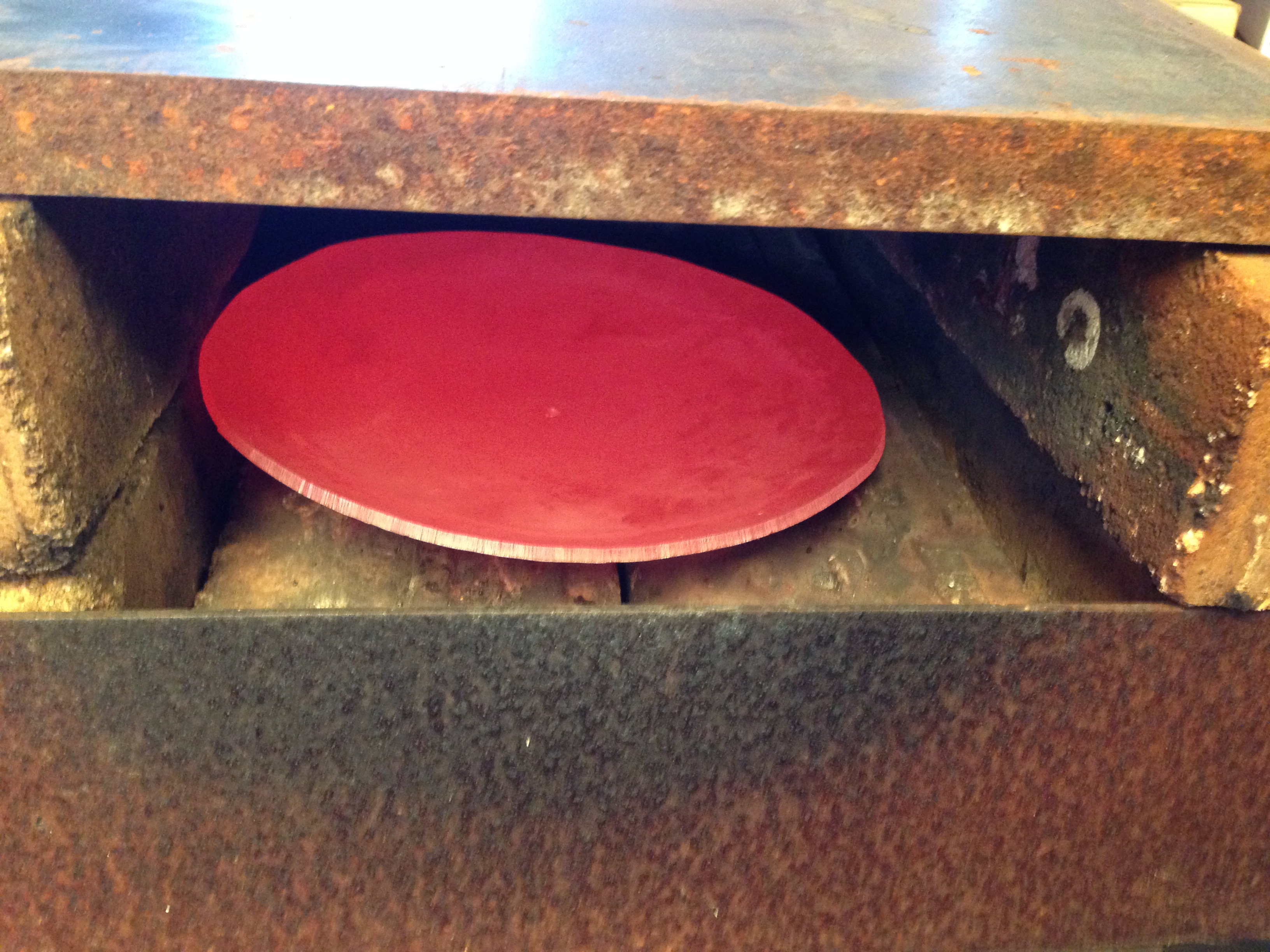
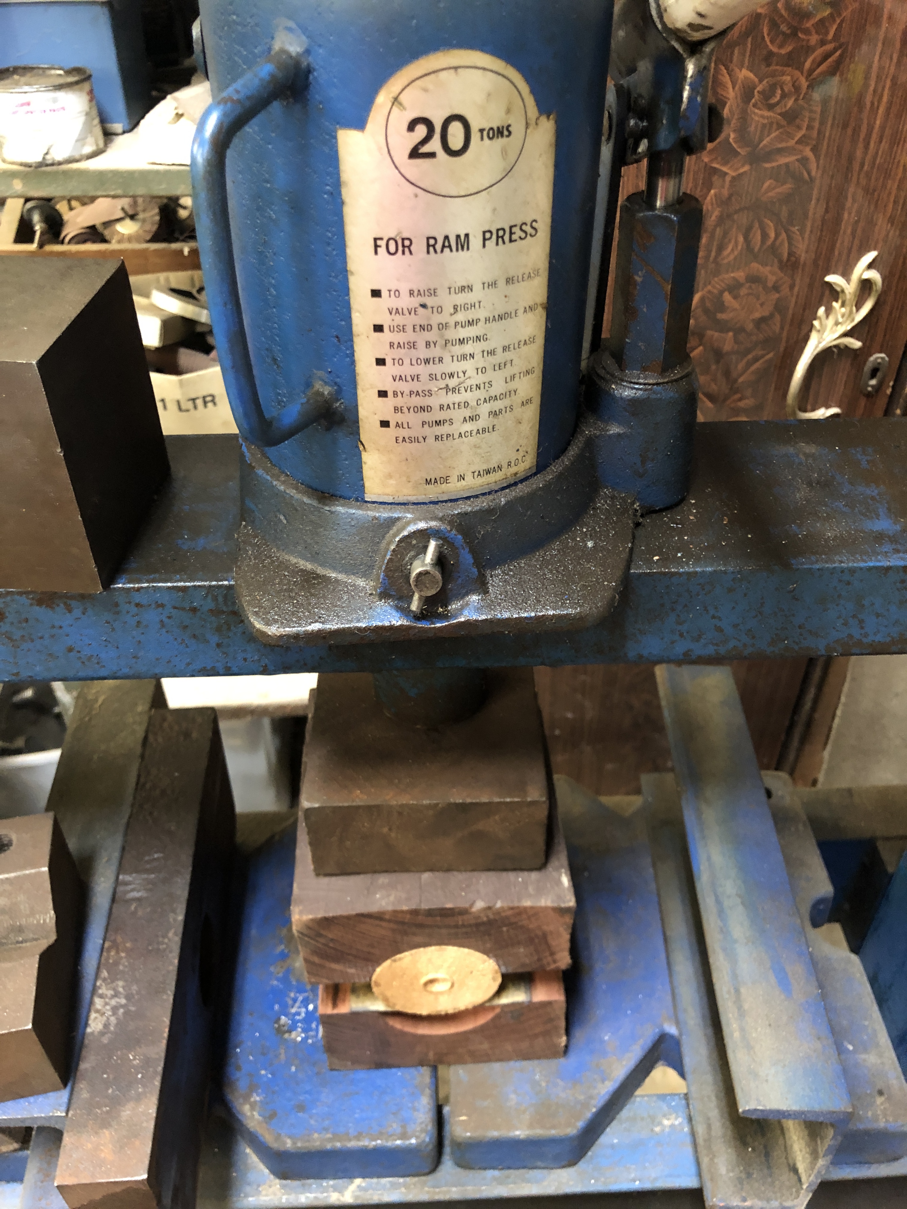
The two projects for which I am currently accumulating materials, will require rolling copper sheet and rod into circular shapes.

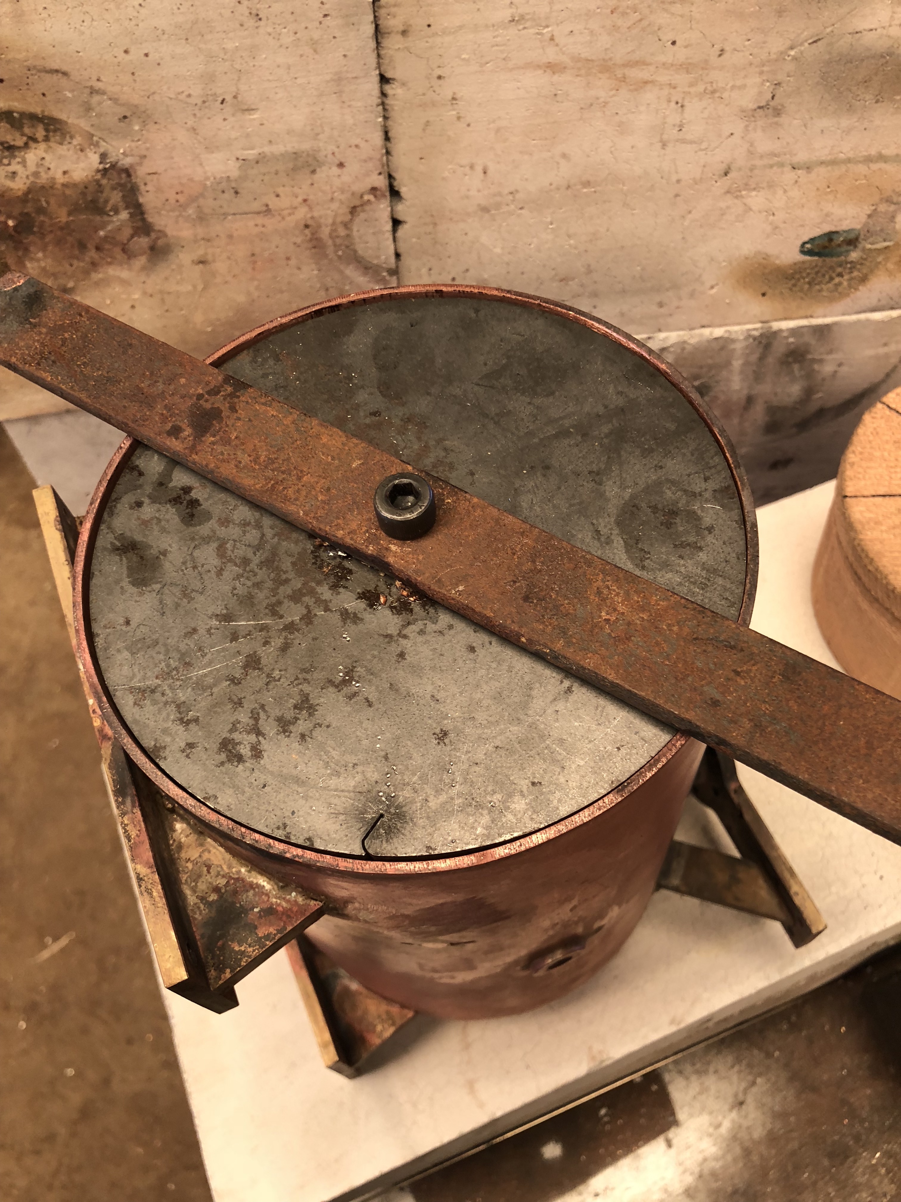
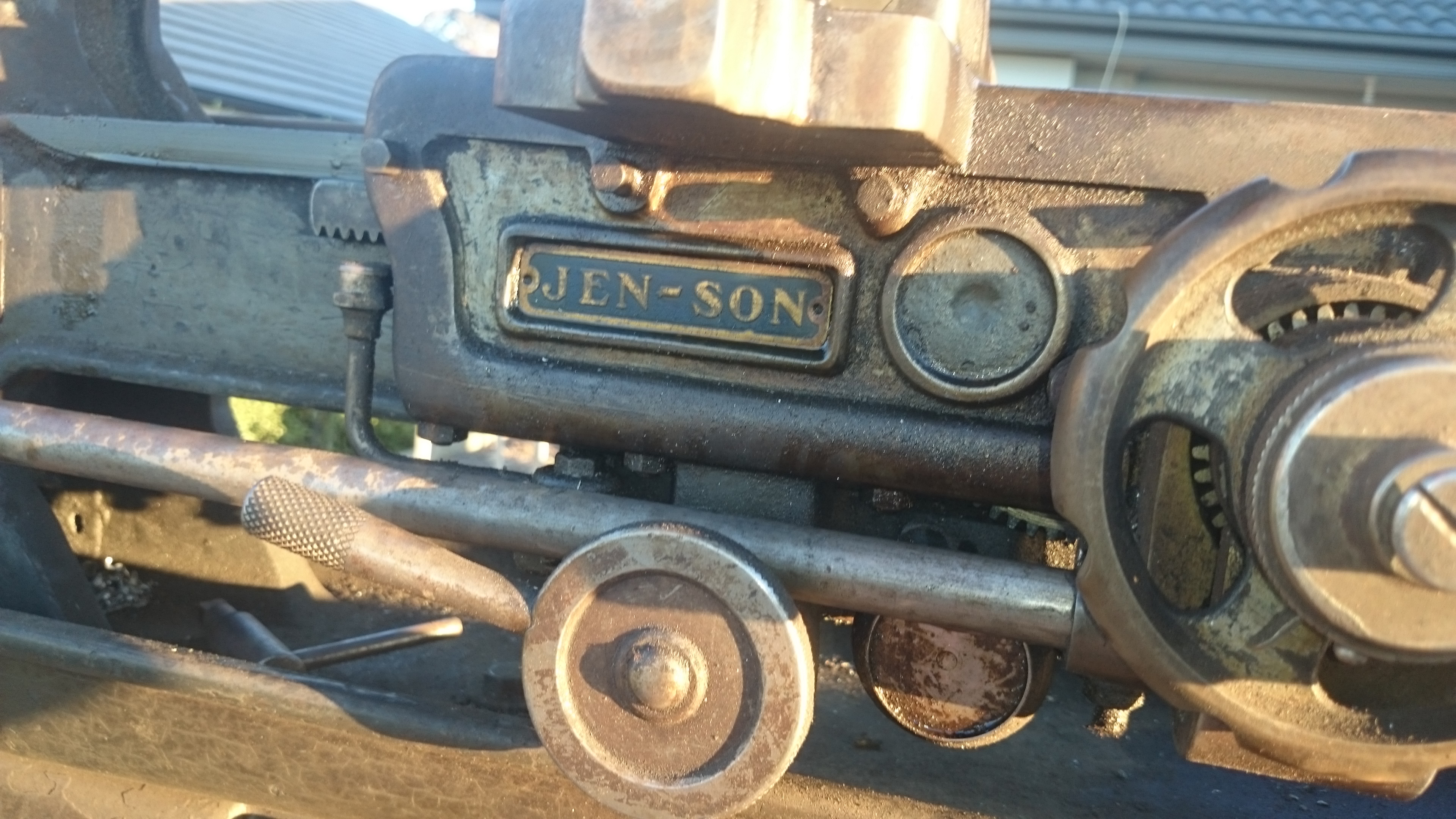
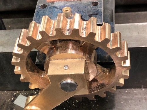
A few years back I made a ring roller to make components for steel gates, and it would have been perfect for rolling the copper foundation rings and fireboxes.

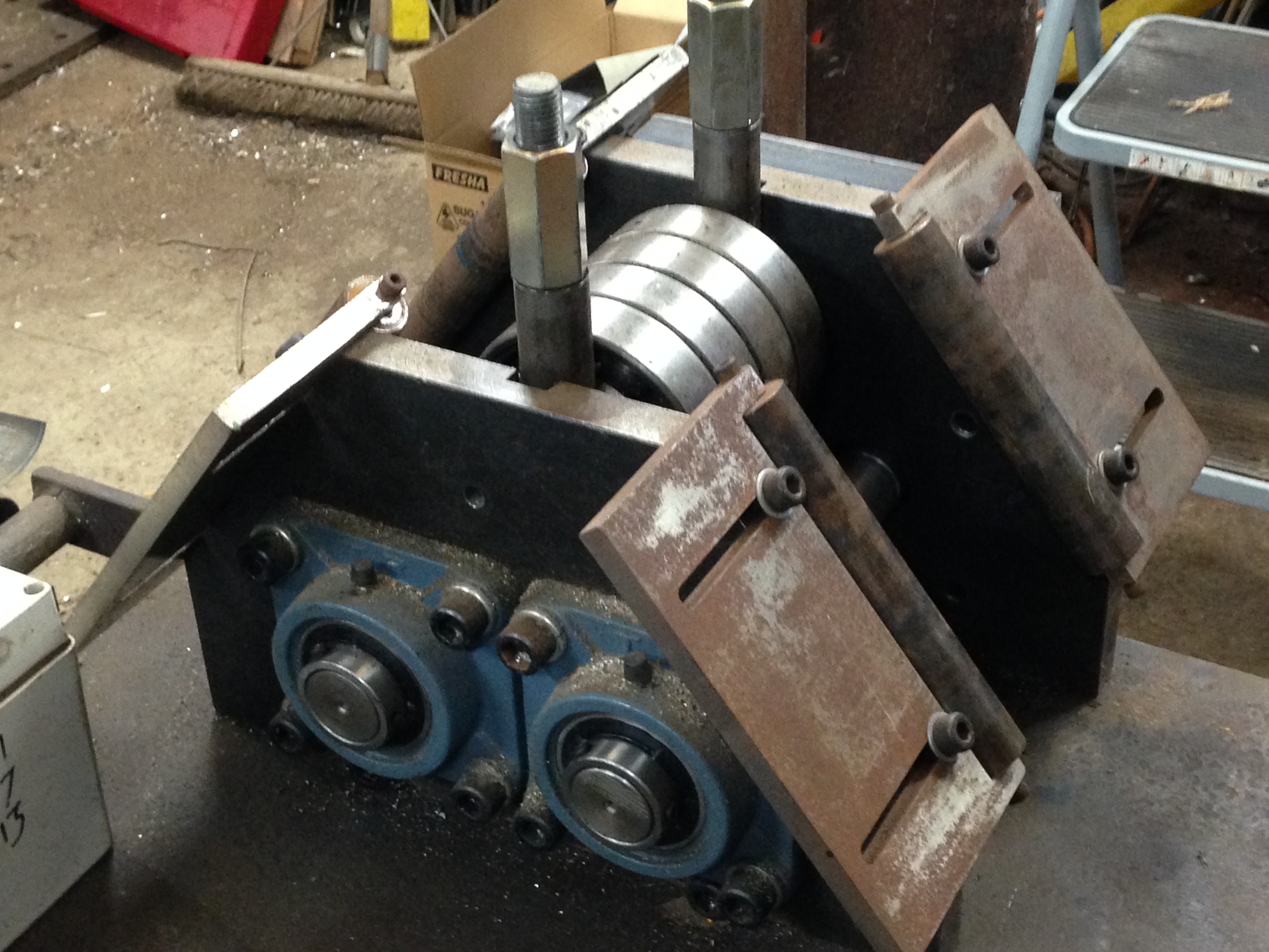
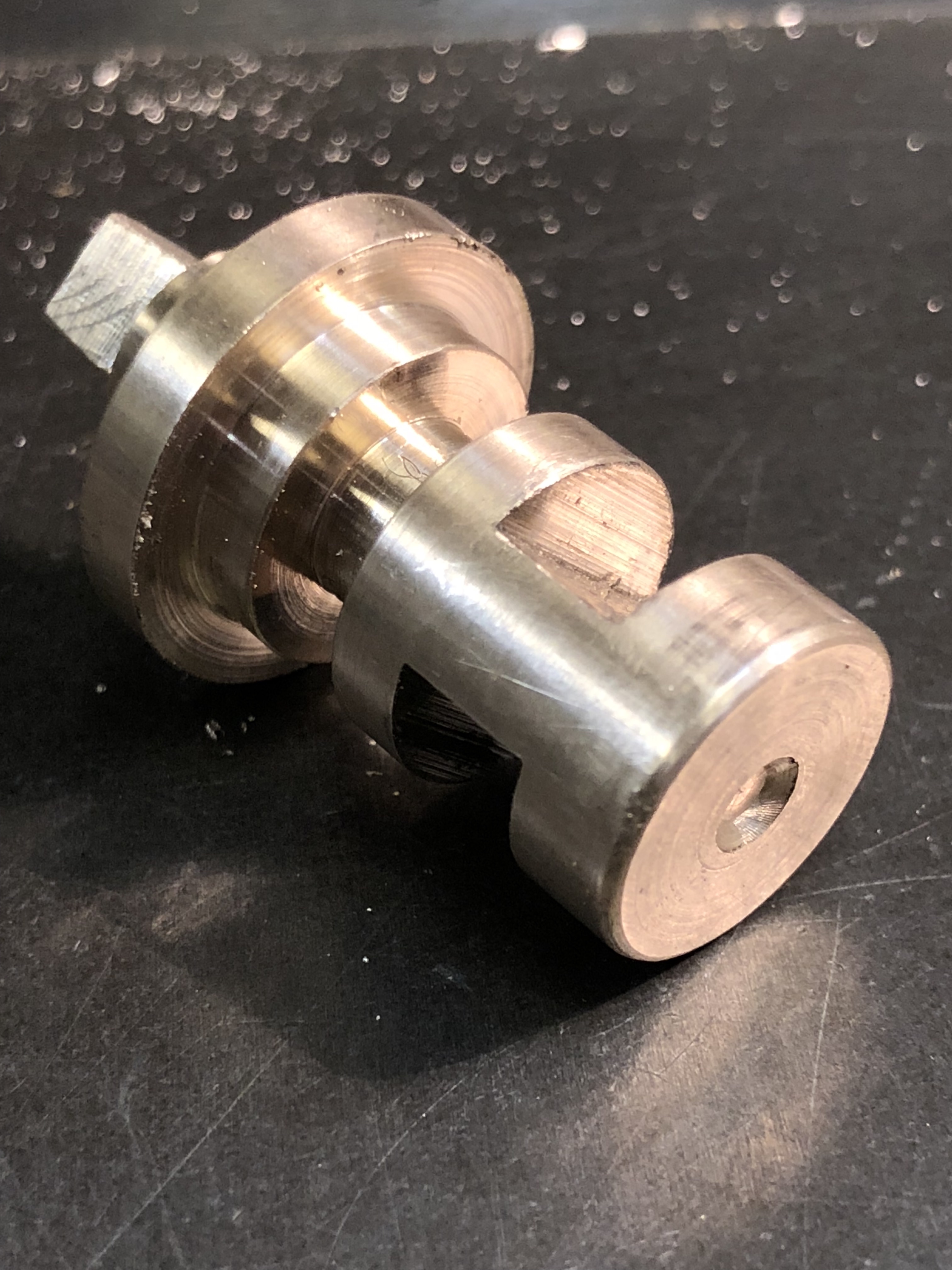
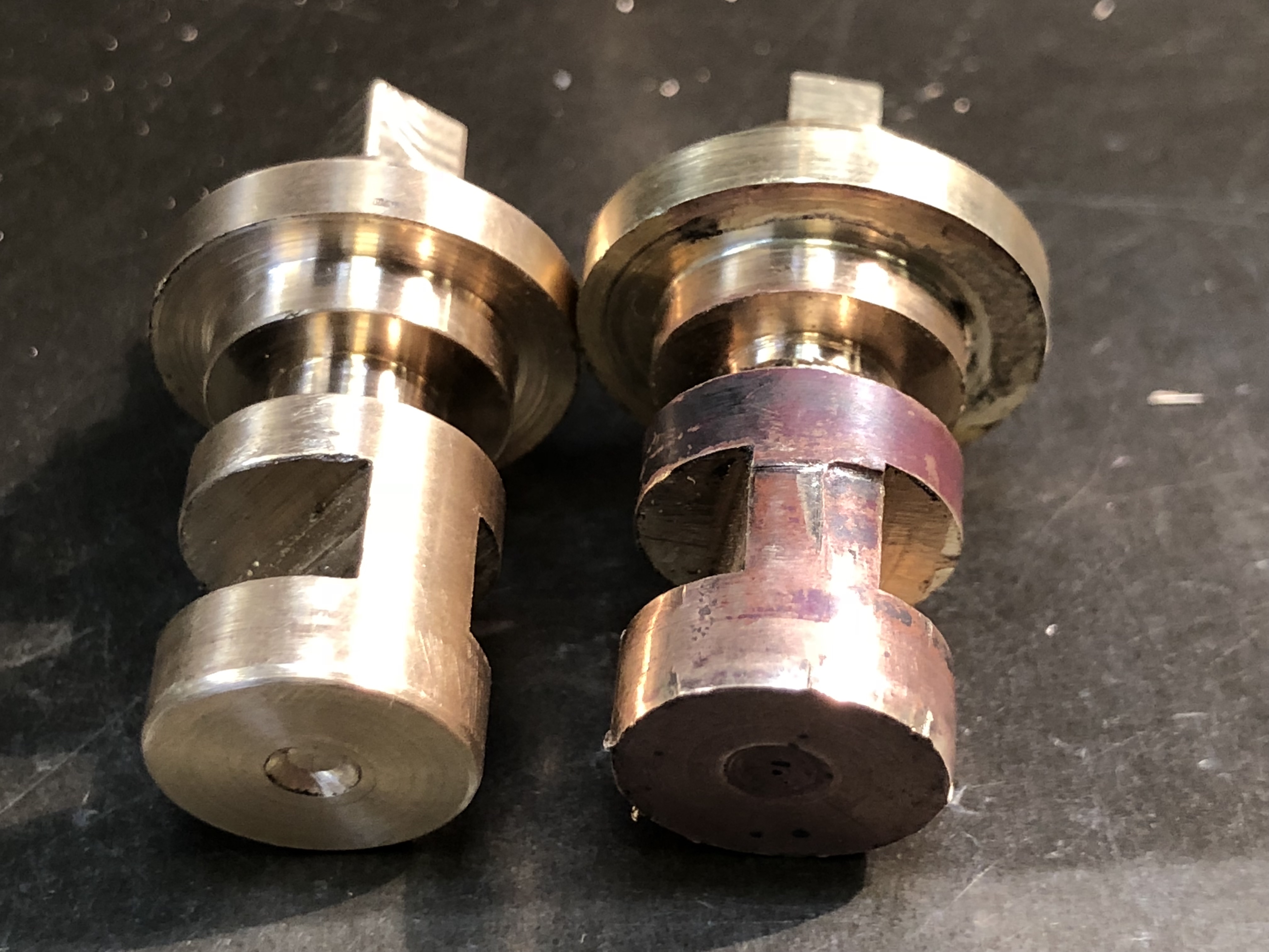
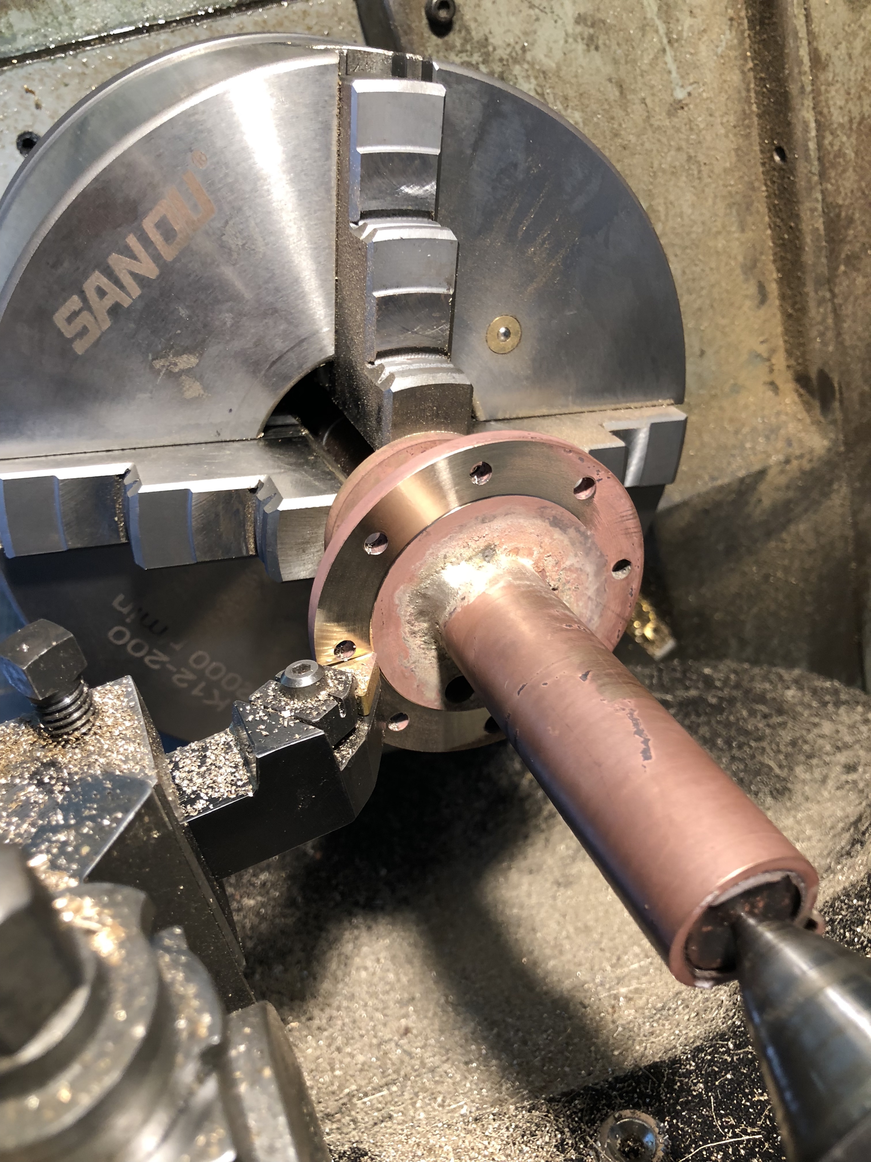
It is fairly heavy duty roller, powered by a 1/2 HP motor, geared down 1:40.  I have bent mild steel up to 1/2″ thick 4″ wide, but I founds its limits when I tried to bend some hardened rod.   It left some grooves in the rollers.   And those grooves would imprint marks into the soft copper, which would be totally unacceptable in the two boiler projects.

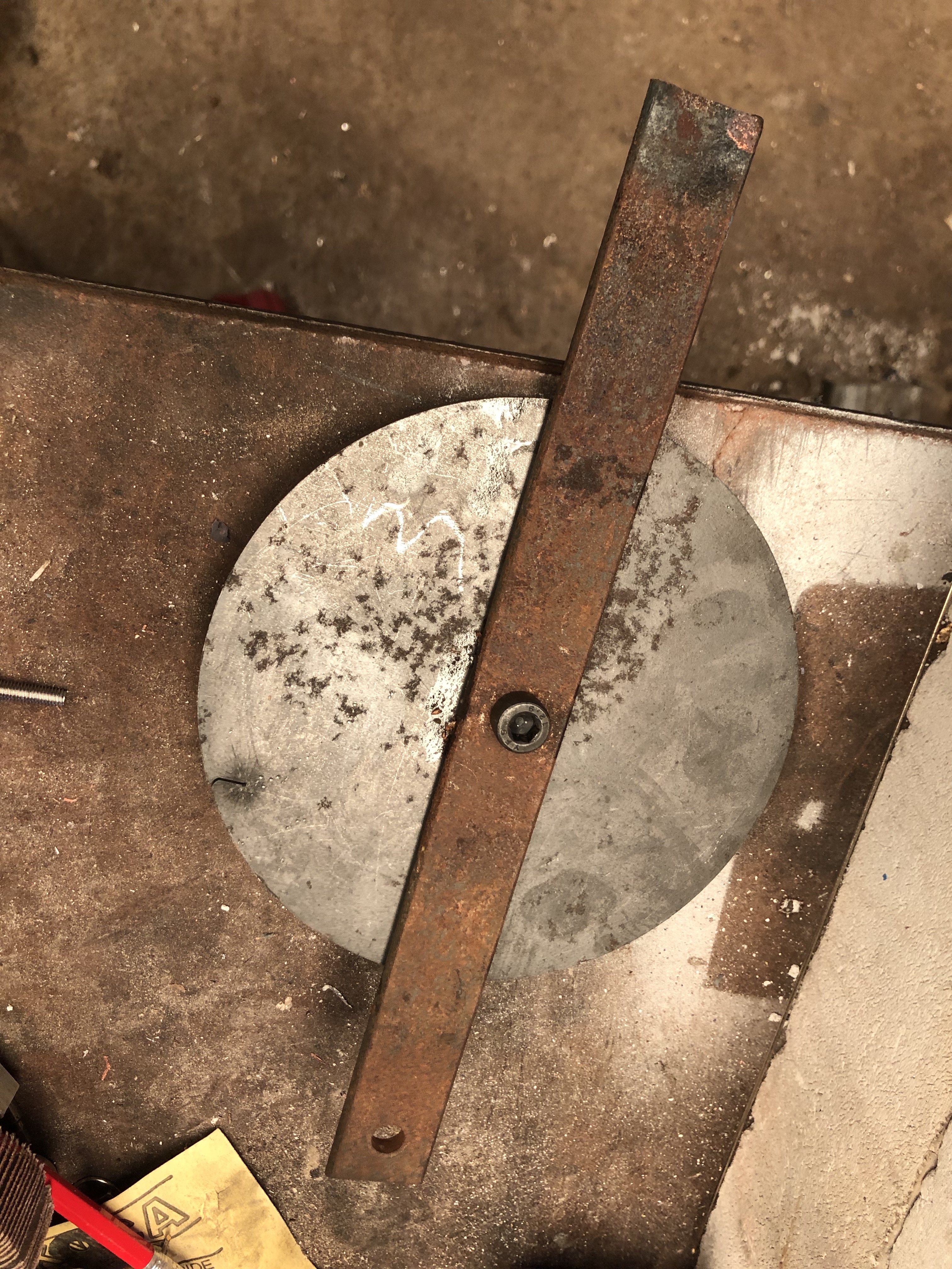
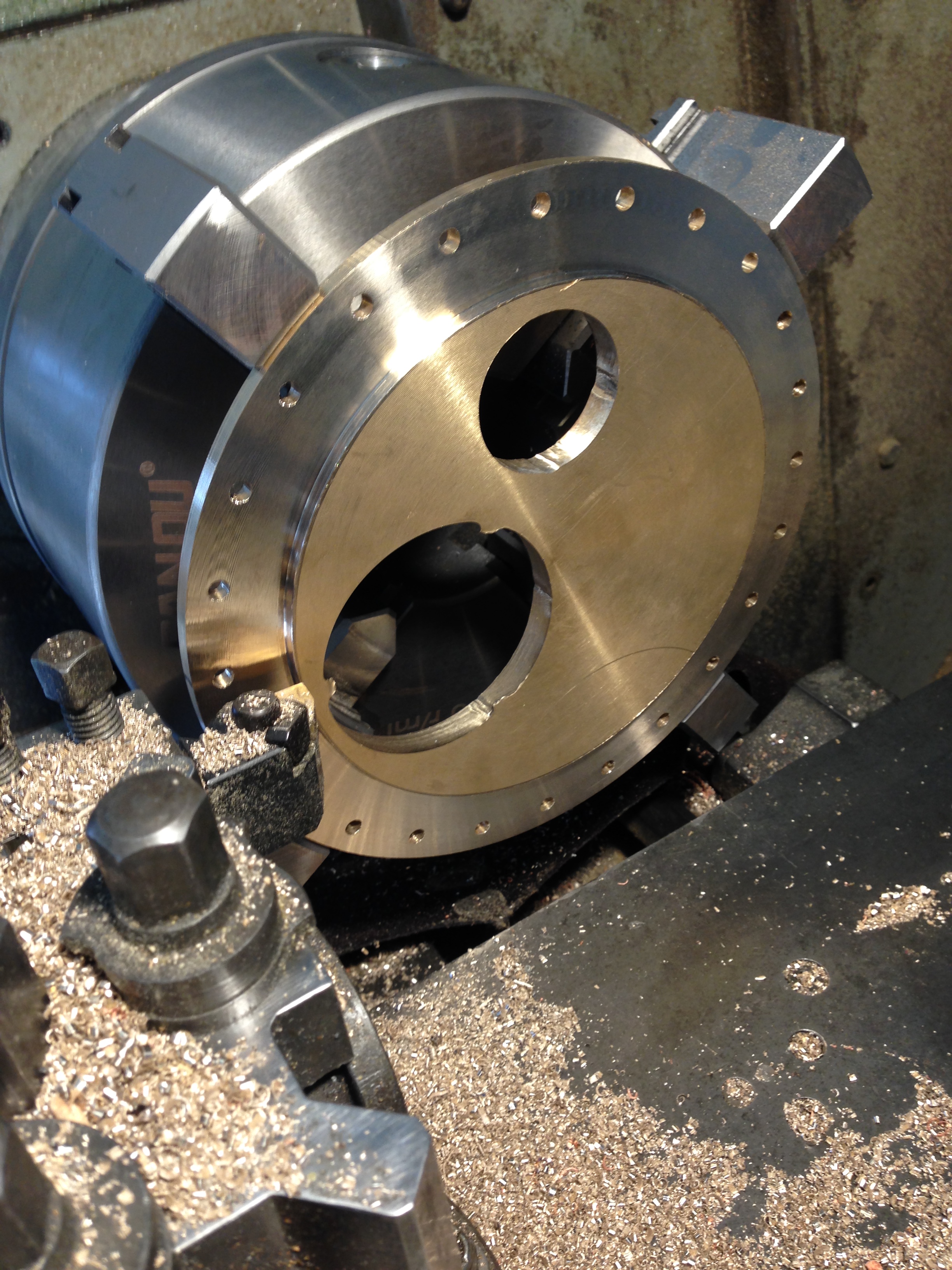
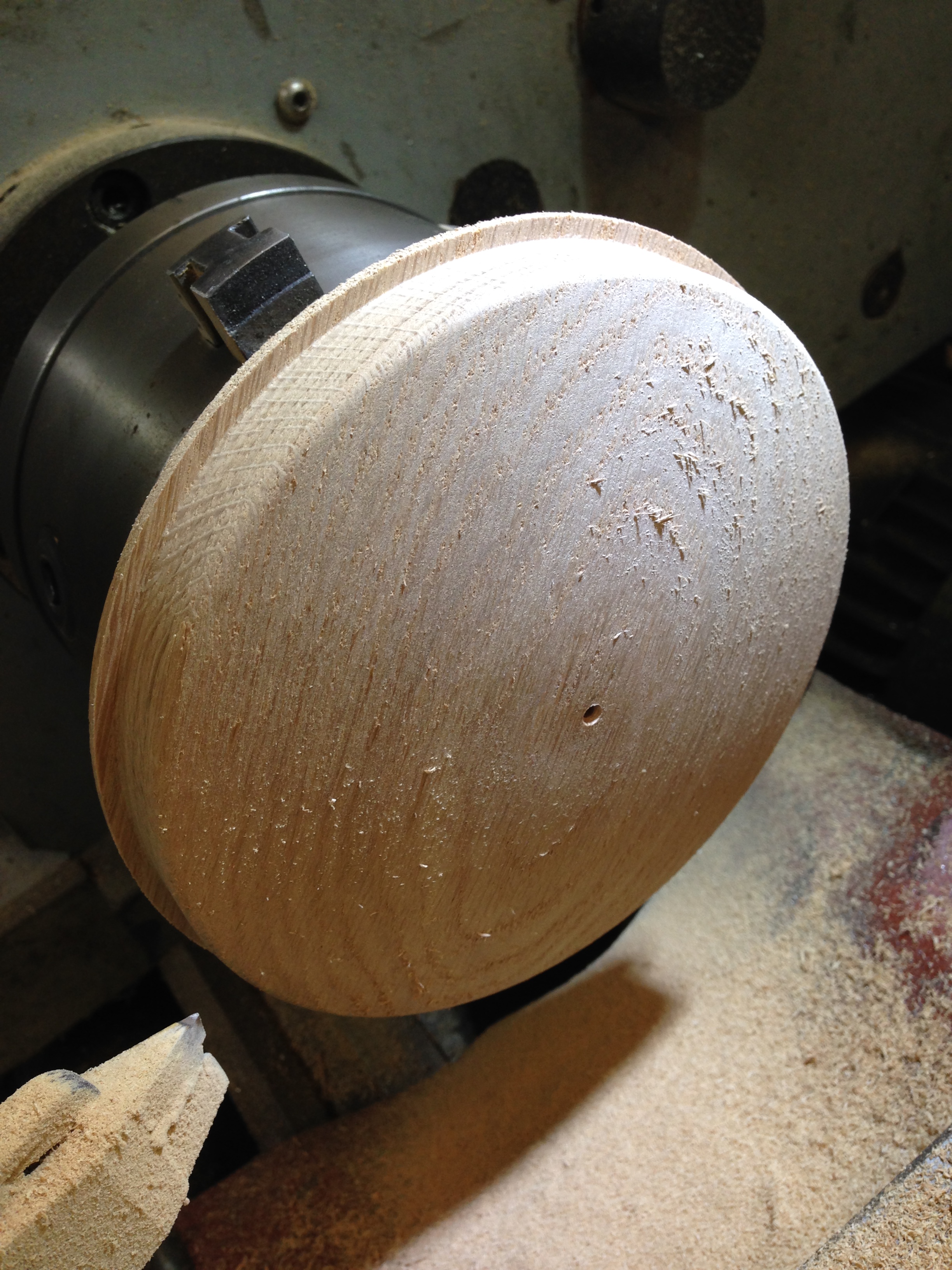
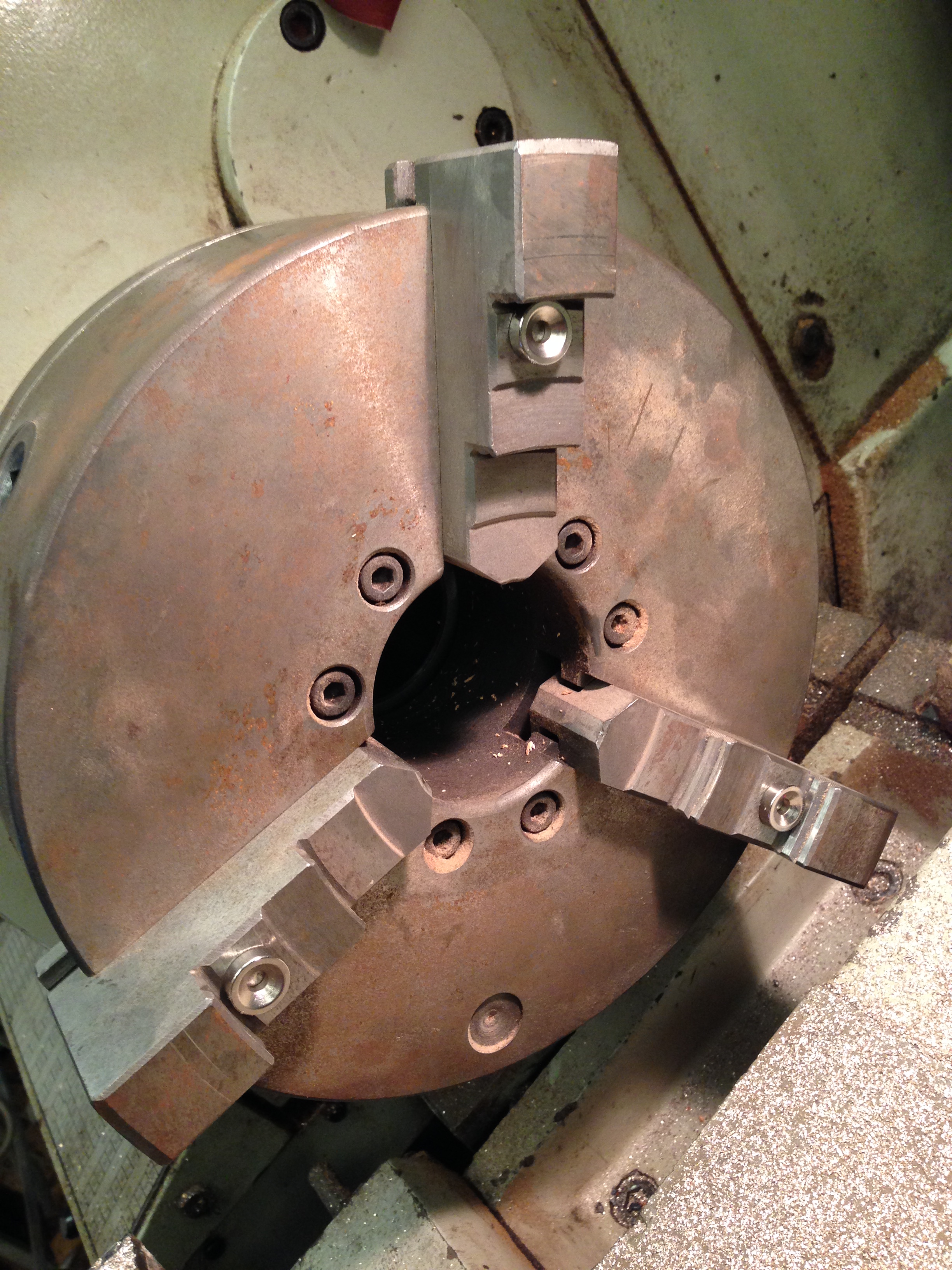
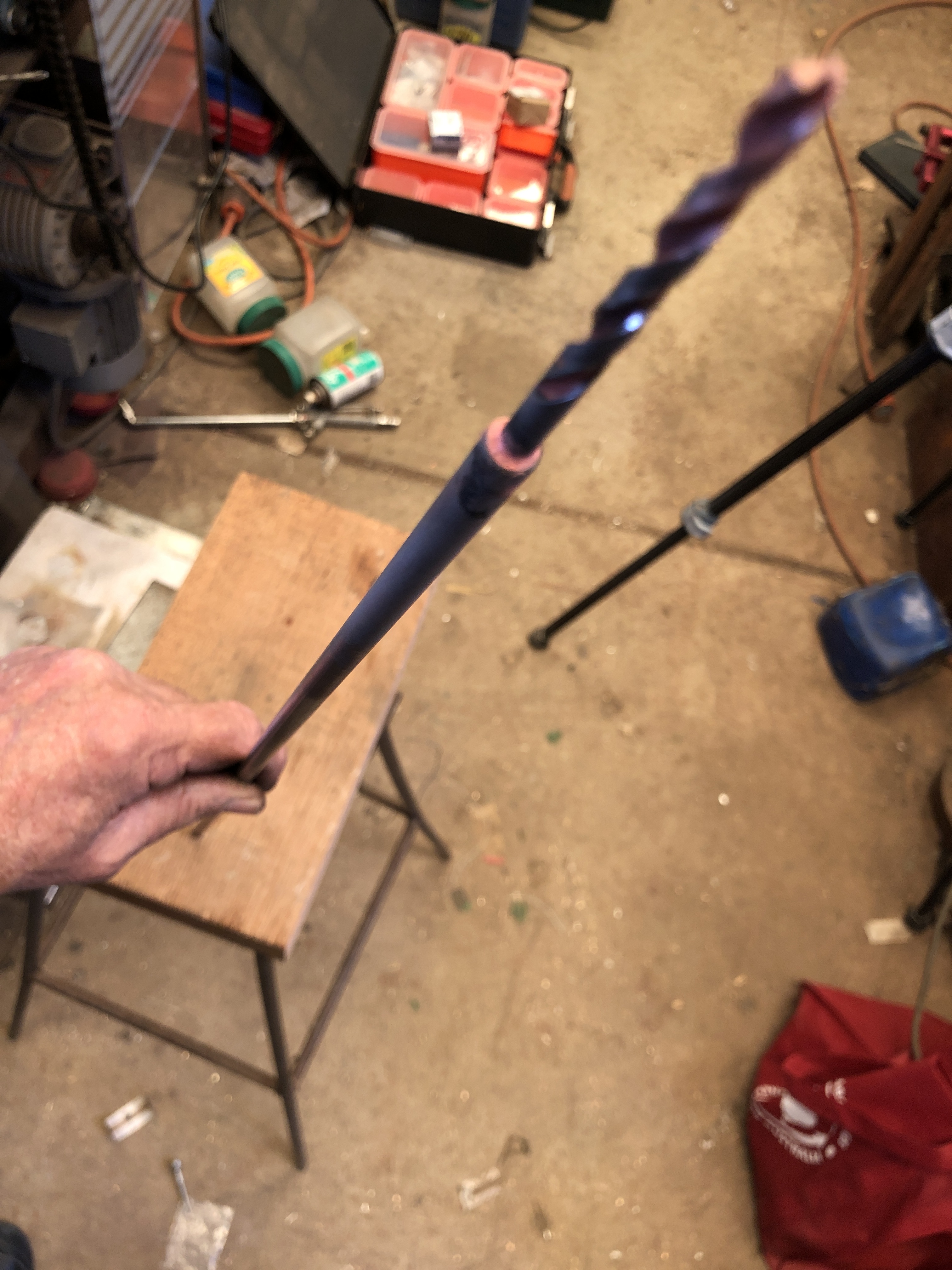
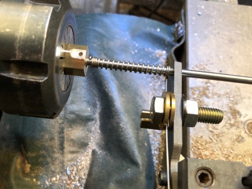
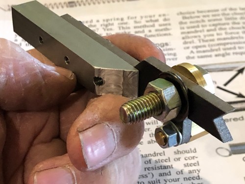
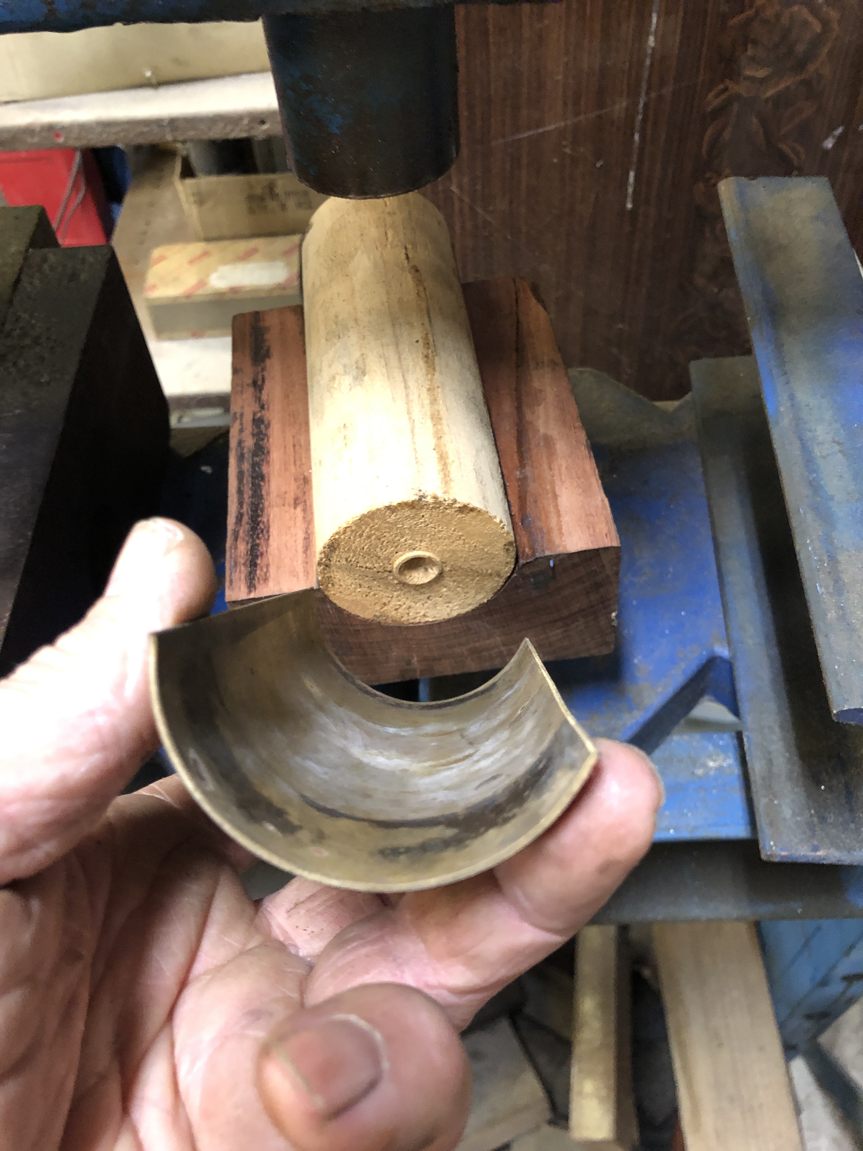
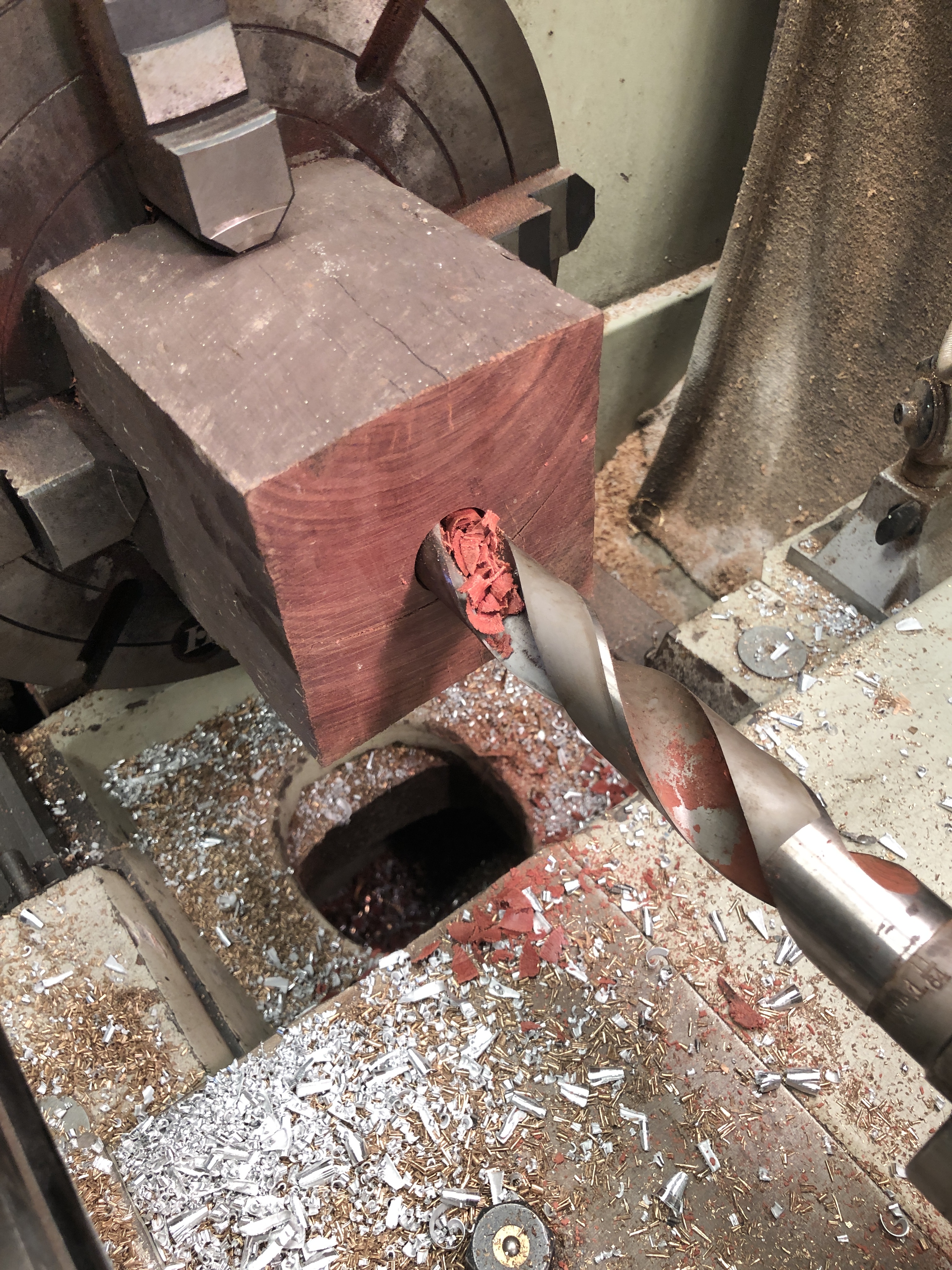
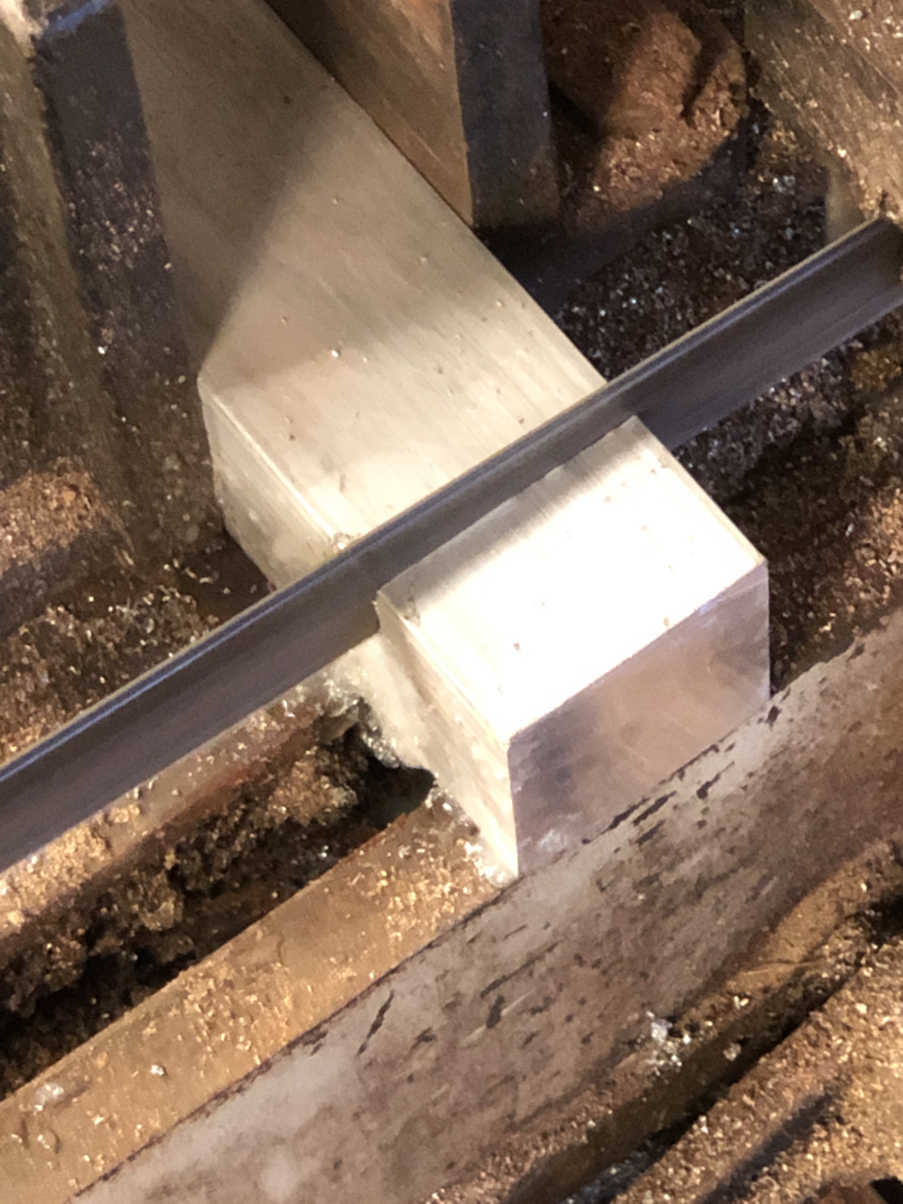
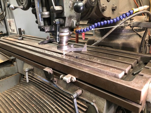
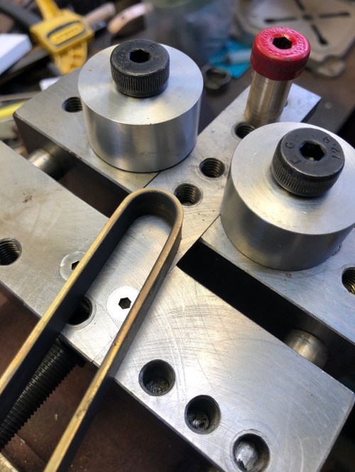
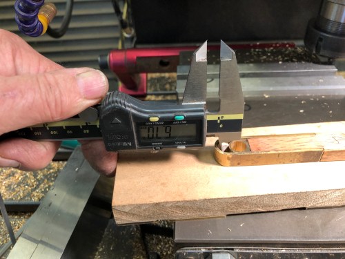
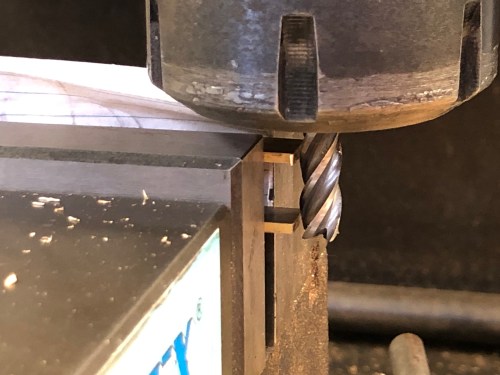
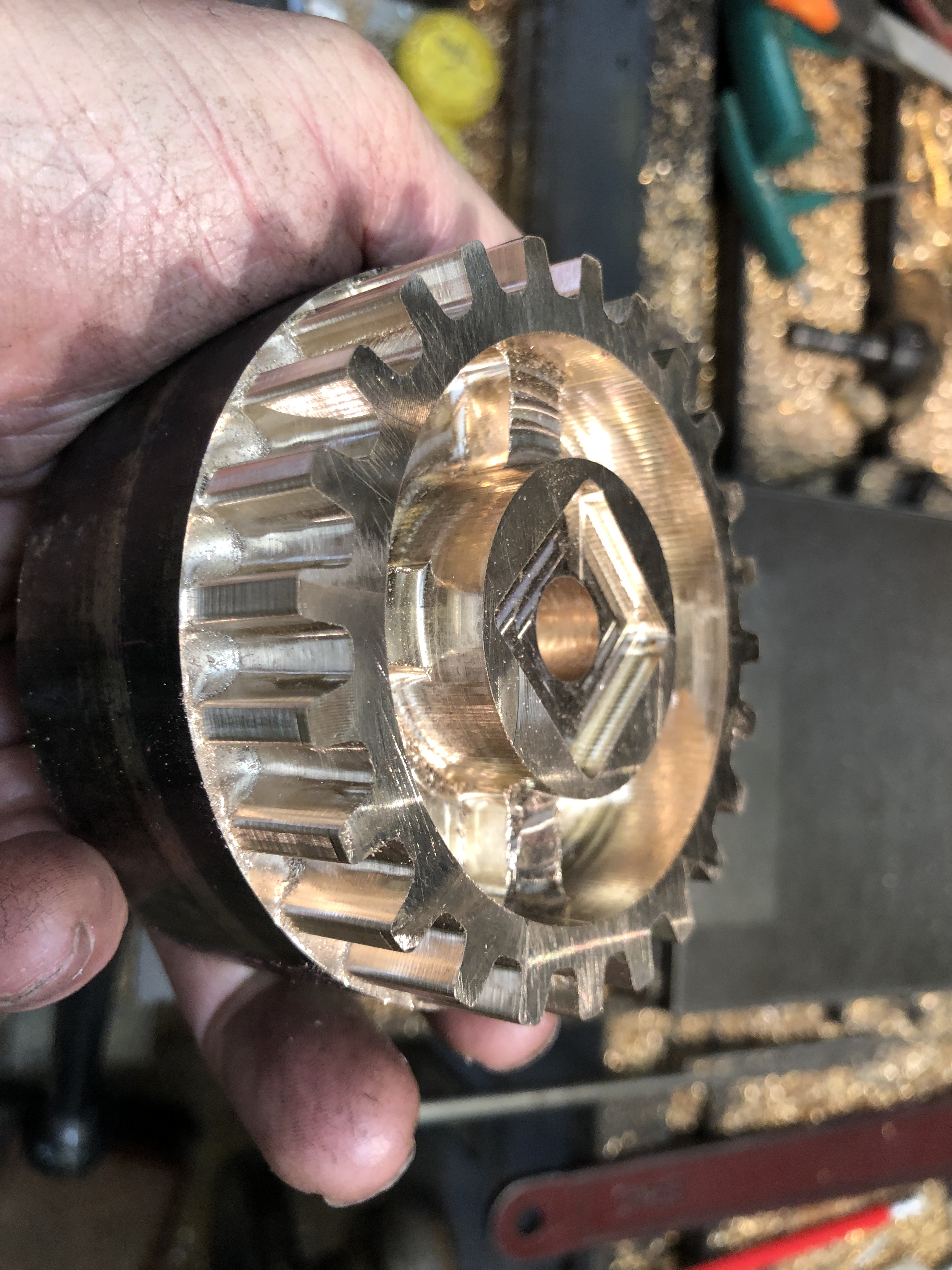
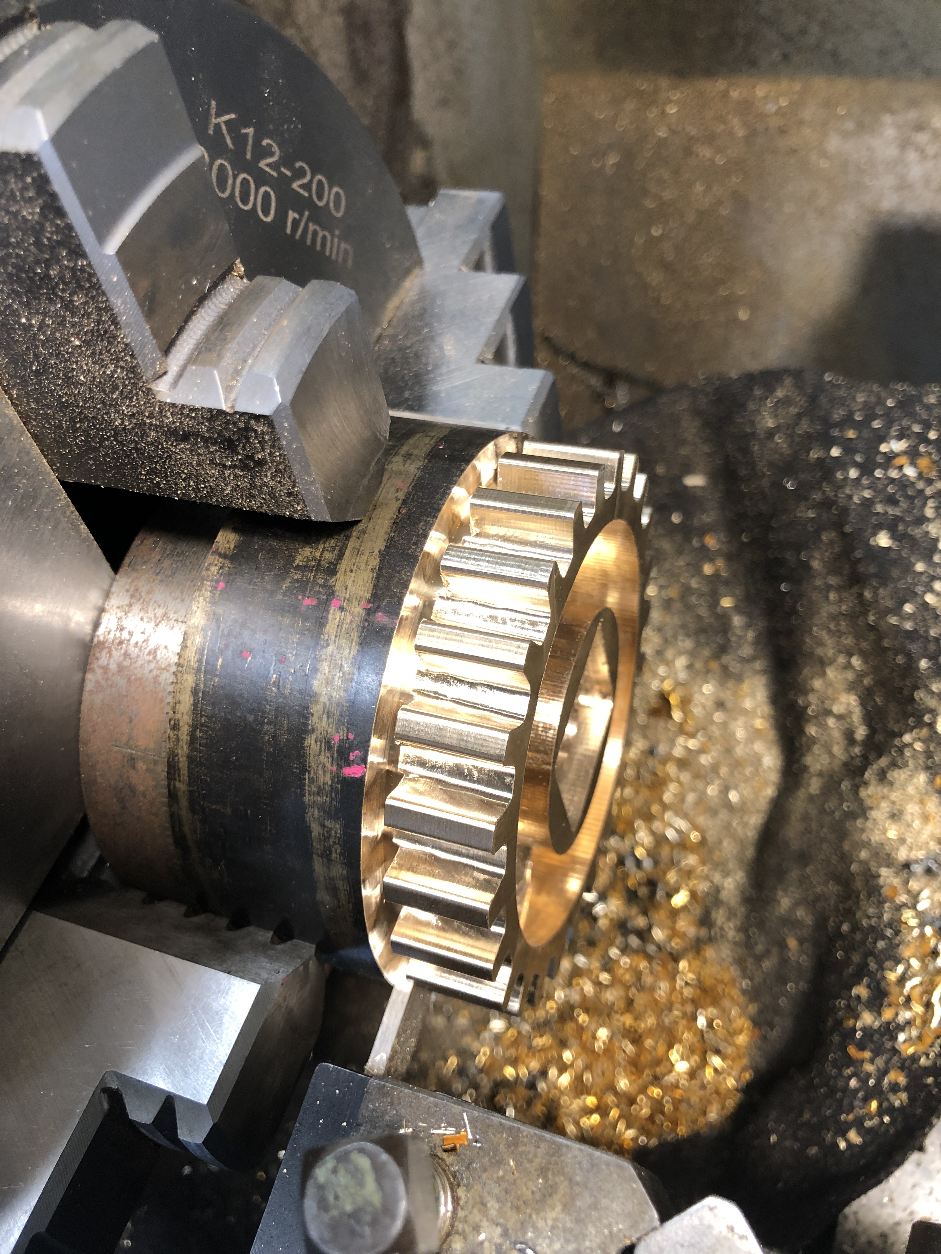
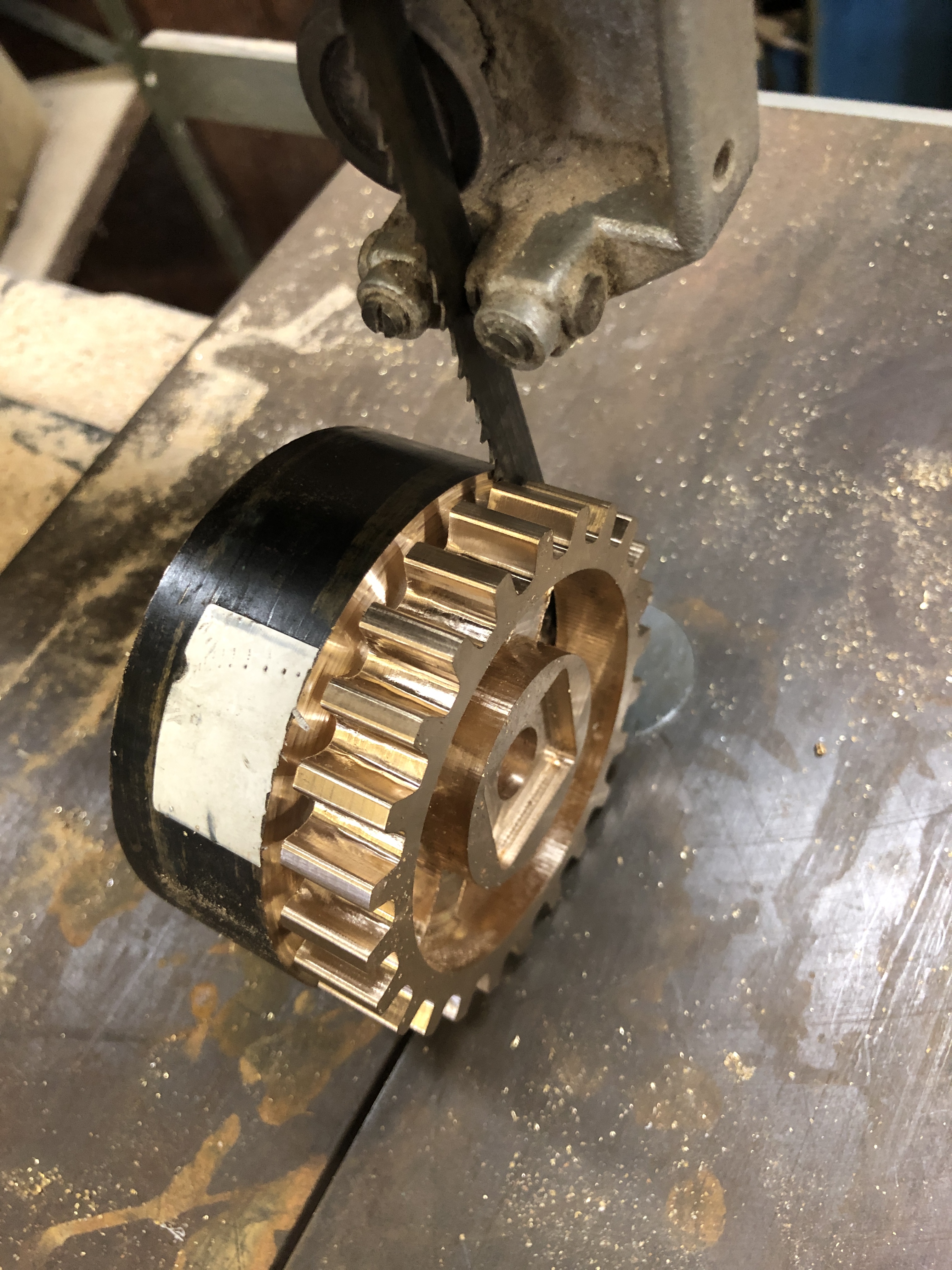
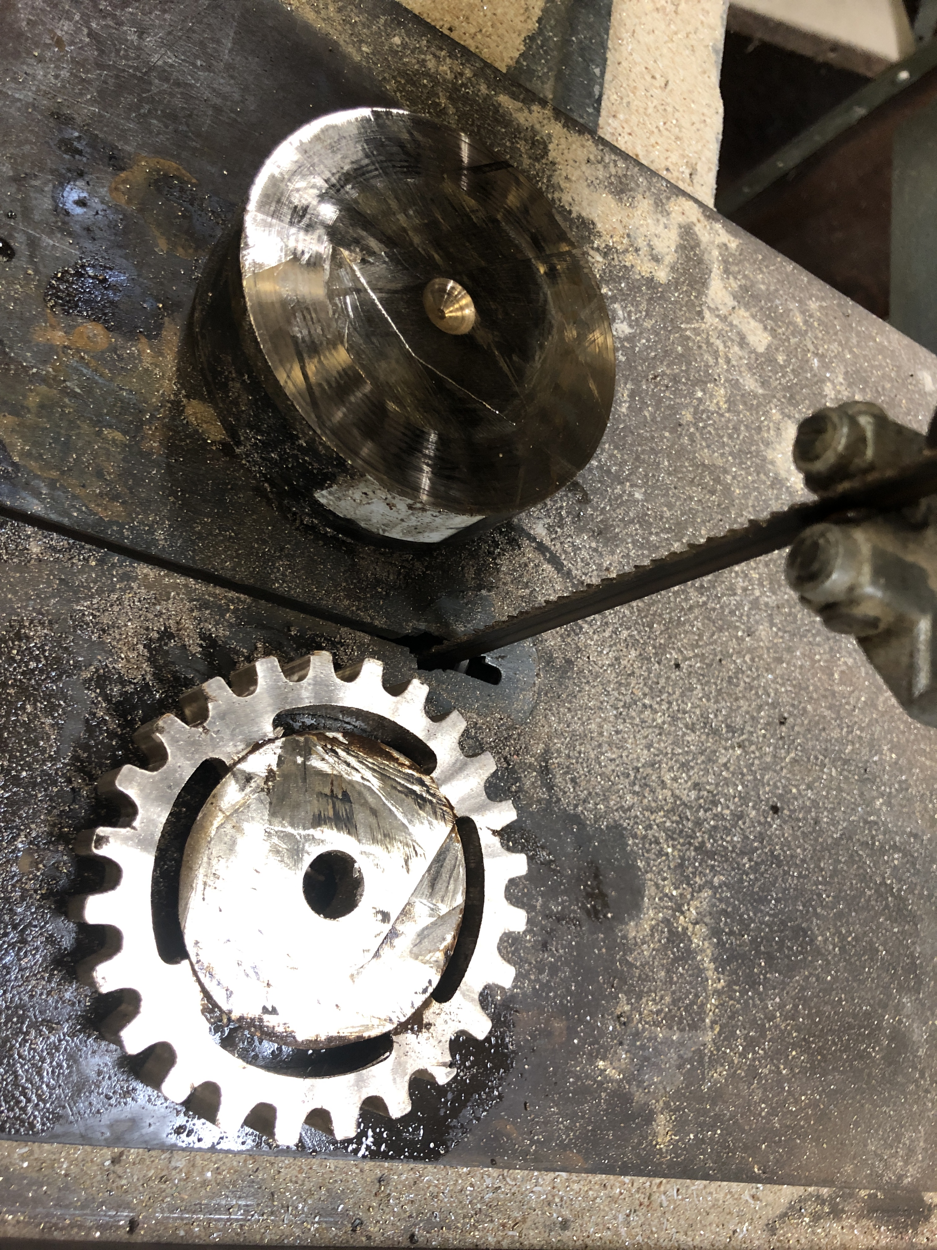
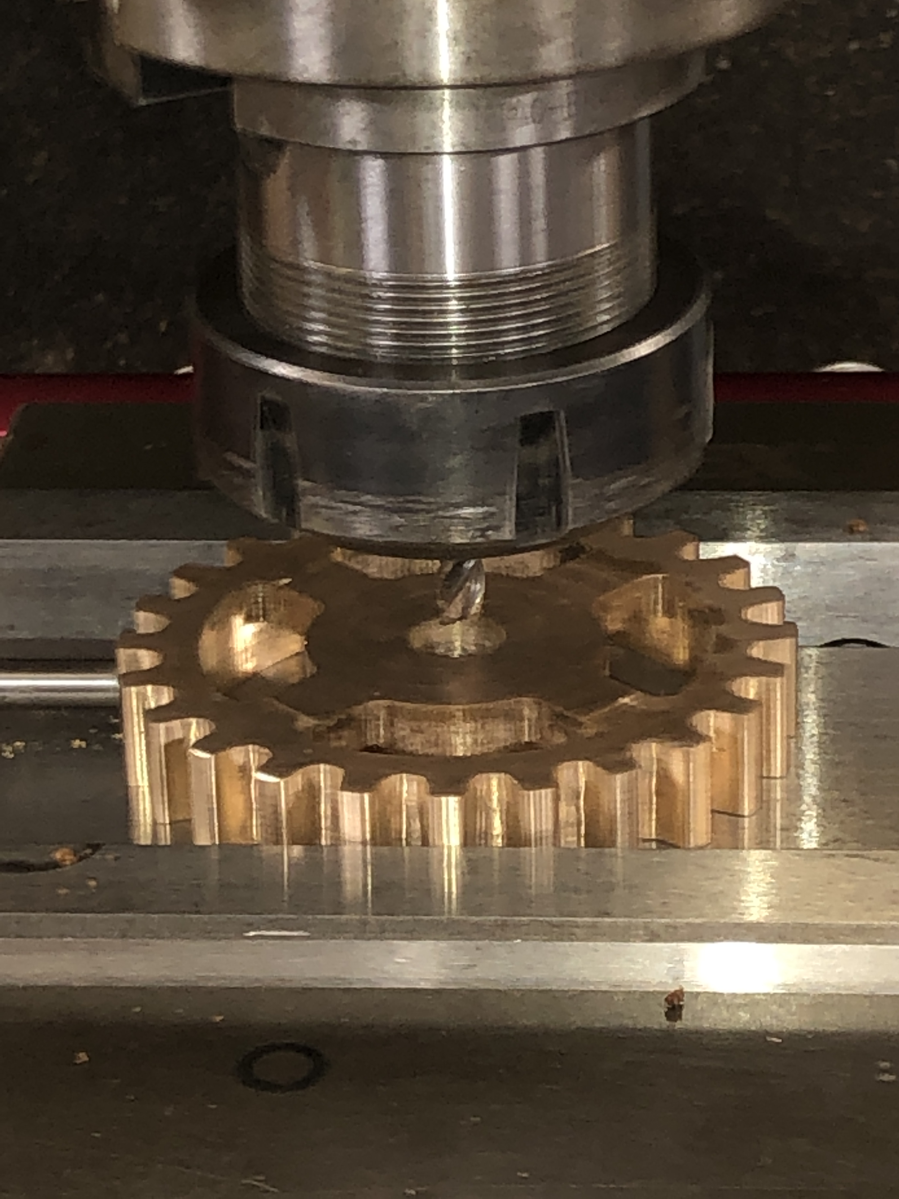
So yesterday I disassembled the machine, removed the rollers, and turned the rolling surfaces in the lathe until the grooves vanished.  The 31.75mm diameter finished at 30.4mm.  Nice and regular and smooth.  And working smoothly again.

Pretty mundane stuff eh?  But oddly satisfying.

IMG_6357

IMG_6360


BRONZE BRAZING

And after that I tried my hand at bronze brazing joins in copper parts.   The boiler inspector requires that certain joins in the boilers use bronze brazing, instead of silver soldering.  I am now reasonably proficient with silver soldering, and had no experience with bronze brazing.  So, do I try to learn a new skill and use it on my expensive copper components of the boilers?   Or do I pay an expert to do the bronze brazing for me?

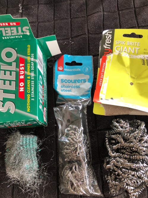
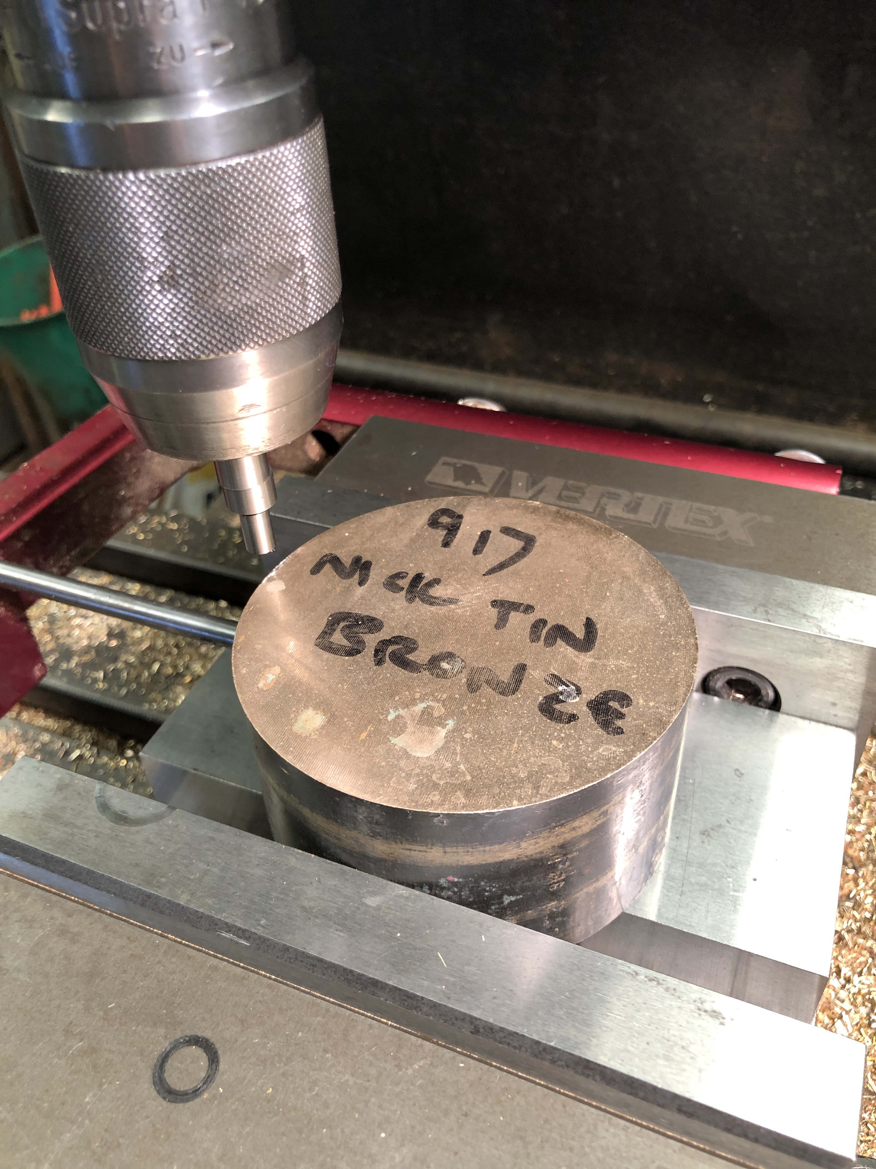
Well, I decided to buy some bronze rods and flux, and give the bronze brazing a try on some copper scrap.  The AMBSC boiler code requires the use of Tobin bronze.  Local welding suppliers had never heard of it, but I found a supplier on ebay.

Tobin bronze.JPG

Tobin bronze is another name for Naval Bronze. (according to my quick Internet “research”).  It is relatively resistant to corrosion, and very strong.  Actually much stronger than silver solder and with a much higher melting point.  Silver solder is said to be as strong as the parent metal, so bronze must be awesome.  Bronze will fill gaps, indeed a V gap is desireable, wheras silver solder prefers an even, tiny space which the solder fills by capillary action.

The brazing rods are available in diameters 1.6, 2.4, and 3.2mm.  I had no idea which size would be best, so I bought 1.6 and 2.4mm.  I also bought some 303 flux powder, even though some experts say that flux is not necessary.  OK, lots to learn.  (p.s. flux IS necessary. )

So, onto YouTube, and watching multiple tutorials on bronze brazing copper.  I reckon that YouTube is fantastic for learning new skills.

With silver soldering, the solder goes to the areas which are fluxed.  But, it seems that when bronze brazing, the bronze follows the heat, so the application of heat is critical.  And not just where the heat is applied, but how much.  The thing is, that the parent metal is not melted in either process (unlike welding).   When bronze brazing copper the temperature range between succesful brazing and melting the parent metal (which means disaster) is quite narrow (about 100ºc), and the brazing temperature is about 950ºc, so it is tricky.

And copper is an excellent heat conductor, so the heat spreads rapidly through the parent metal, with result that the bronze filler spreads and it is difficult to get a good appearance.

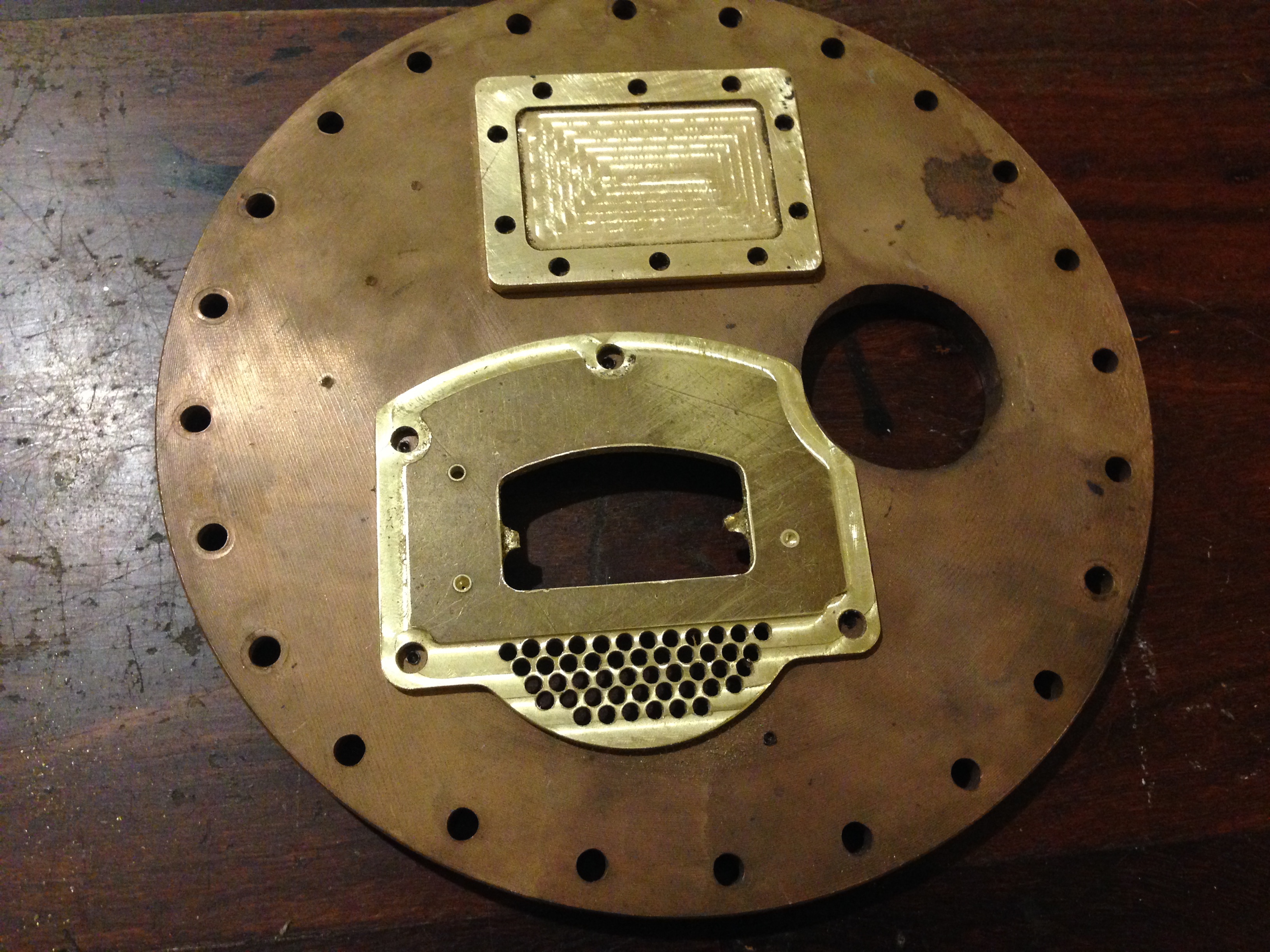
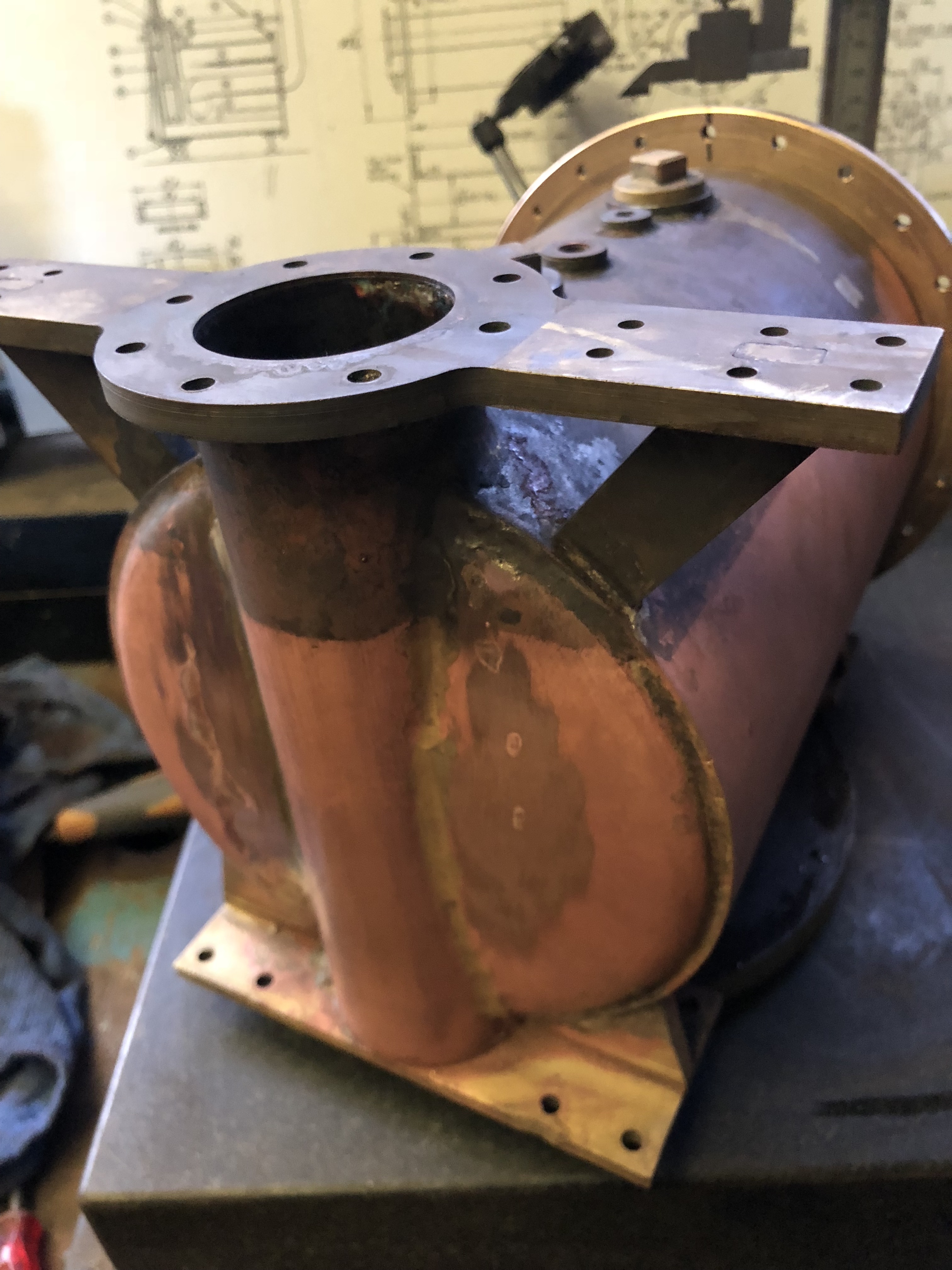
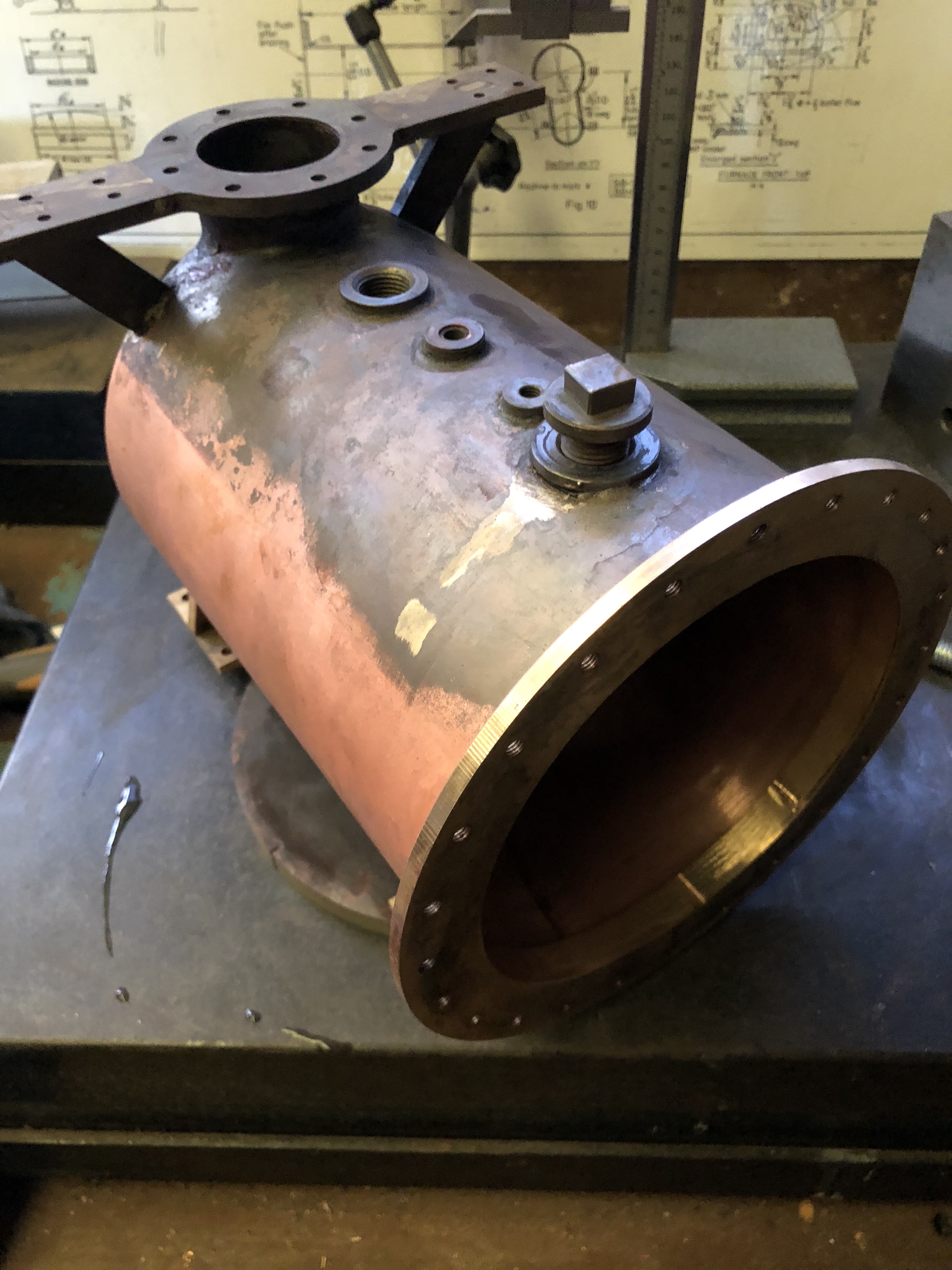
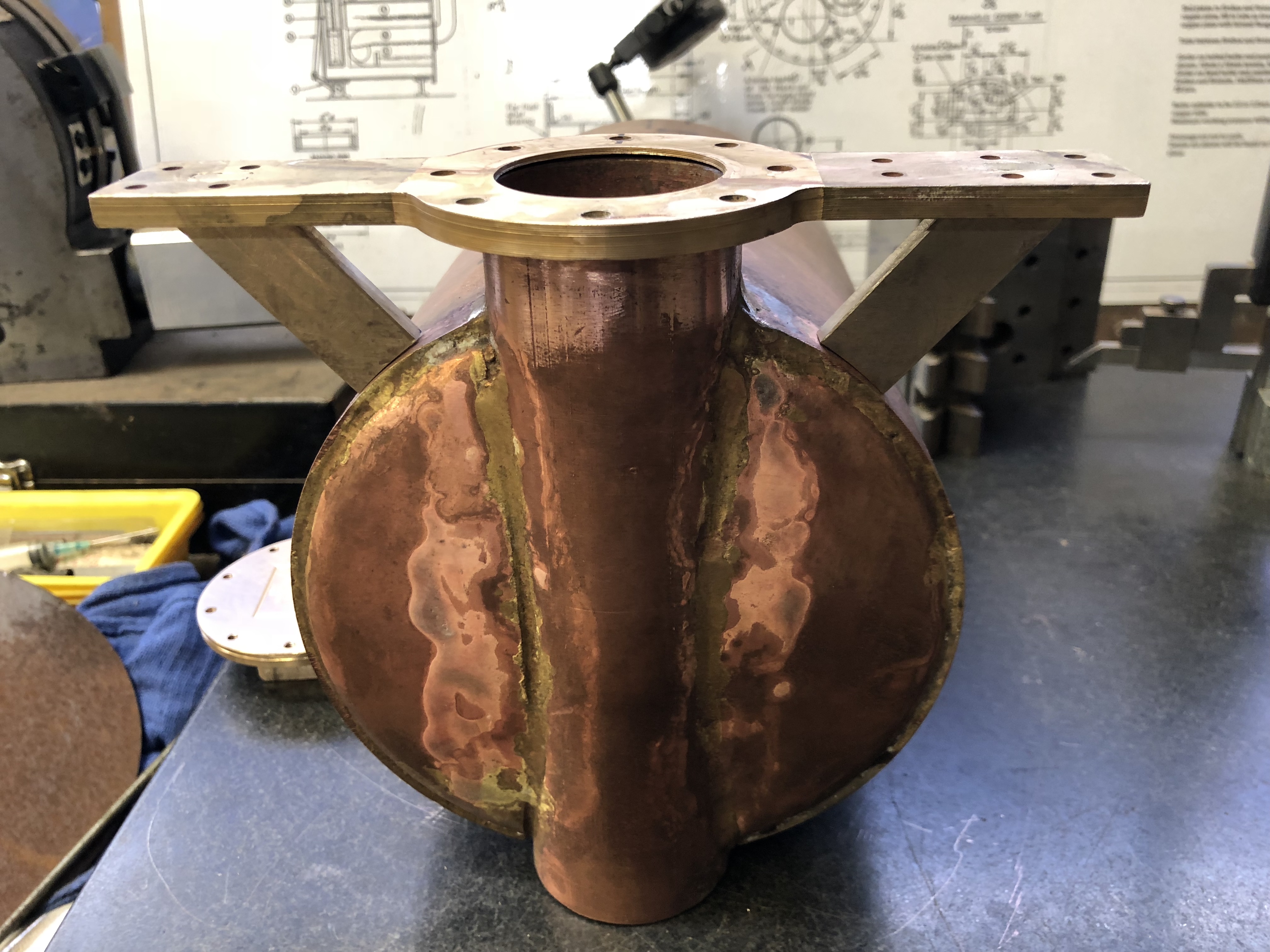
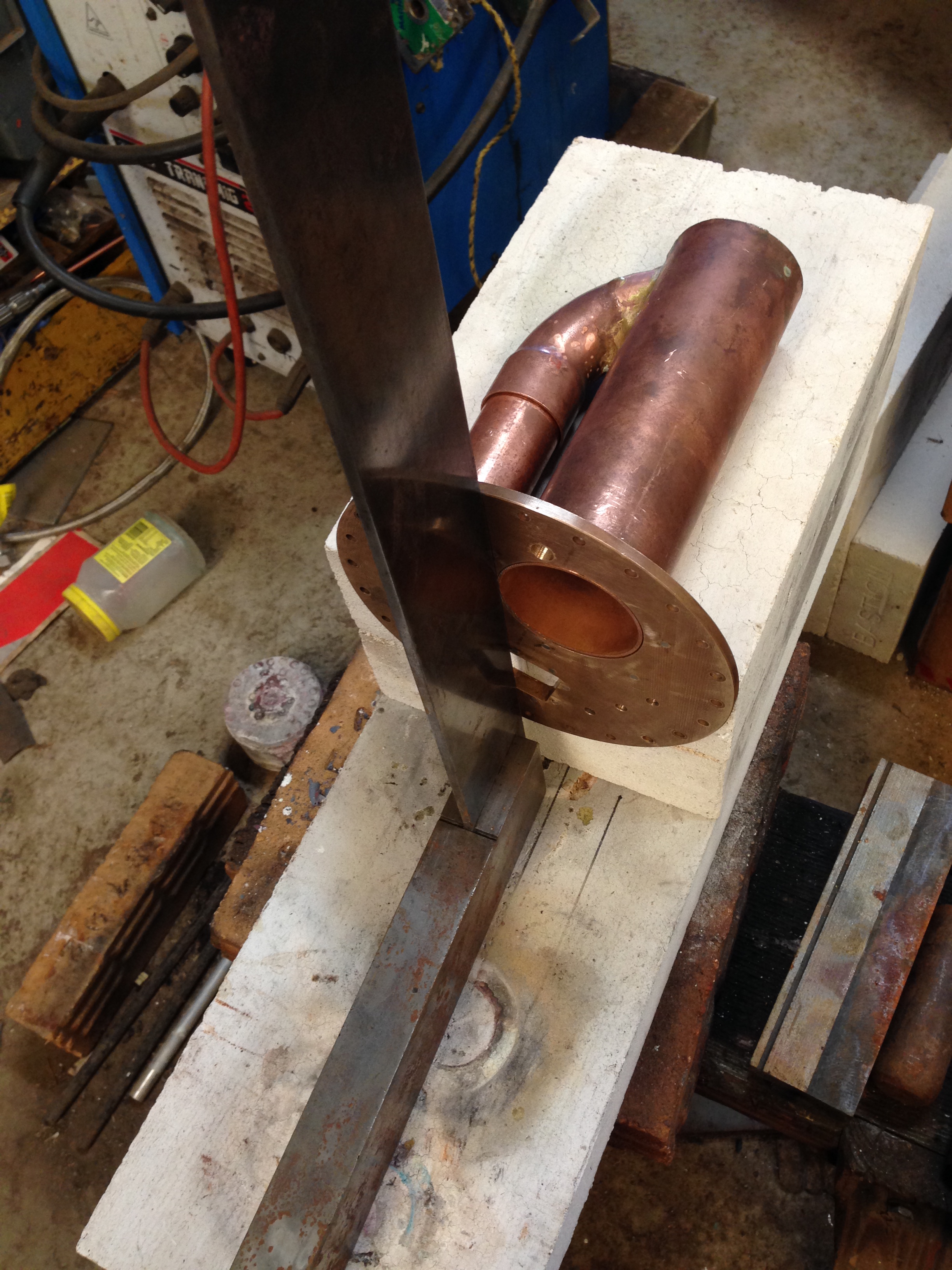
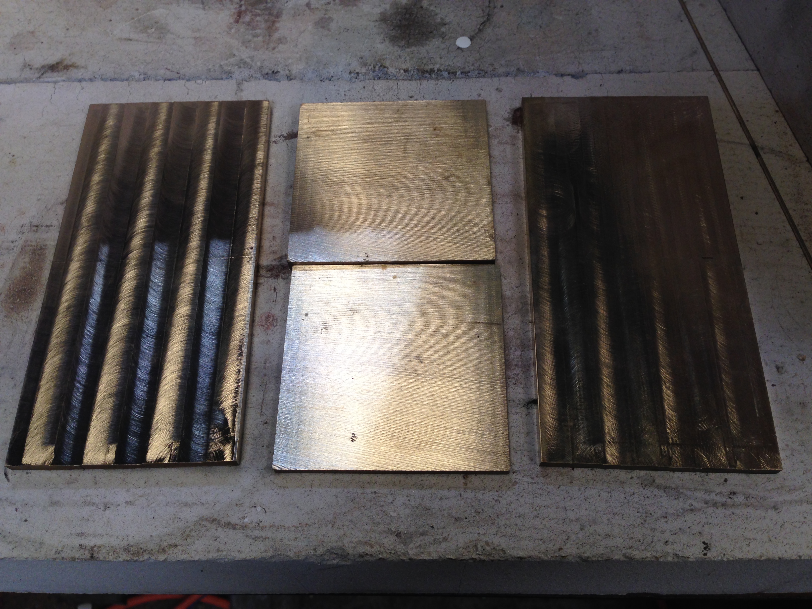
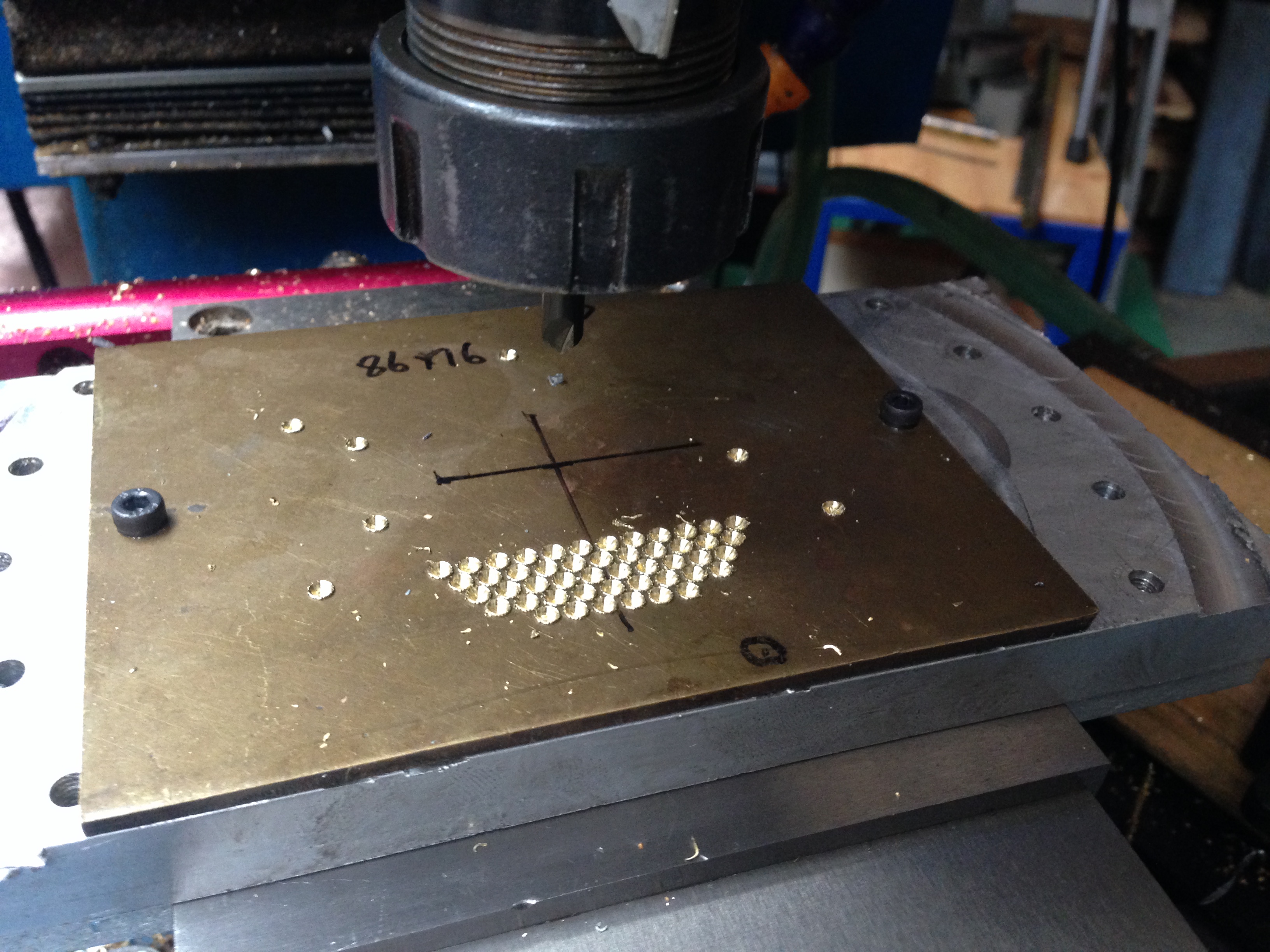
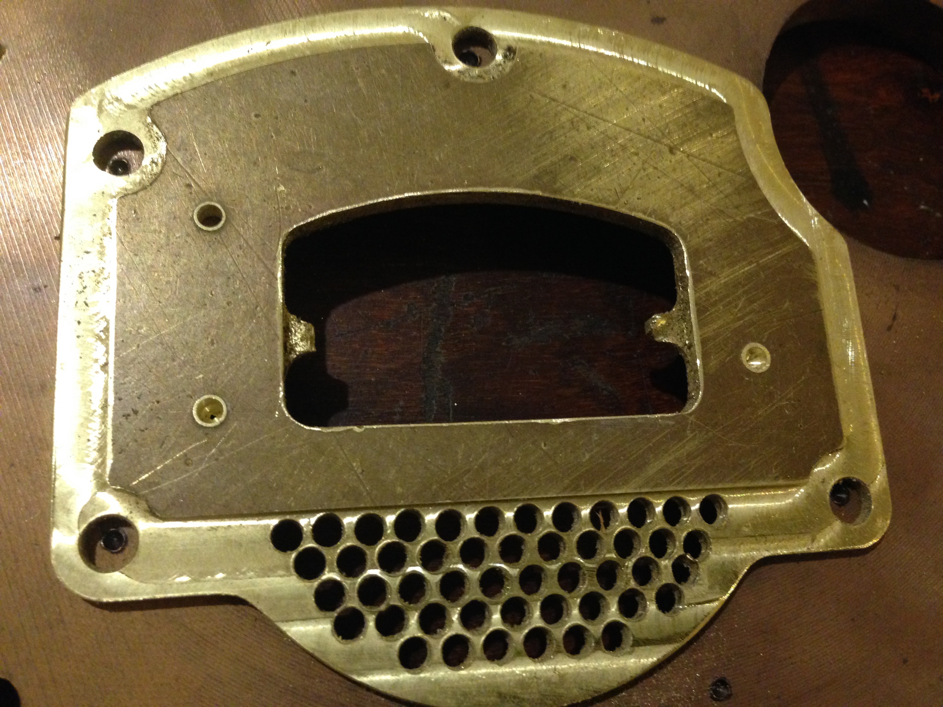
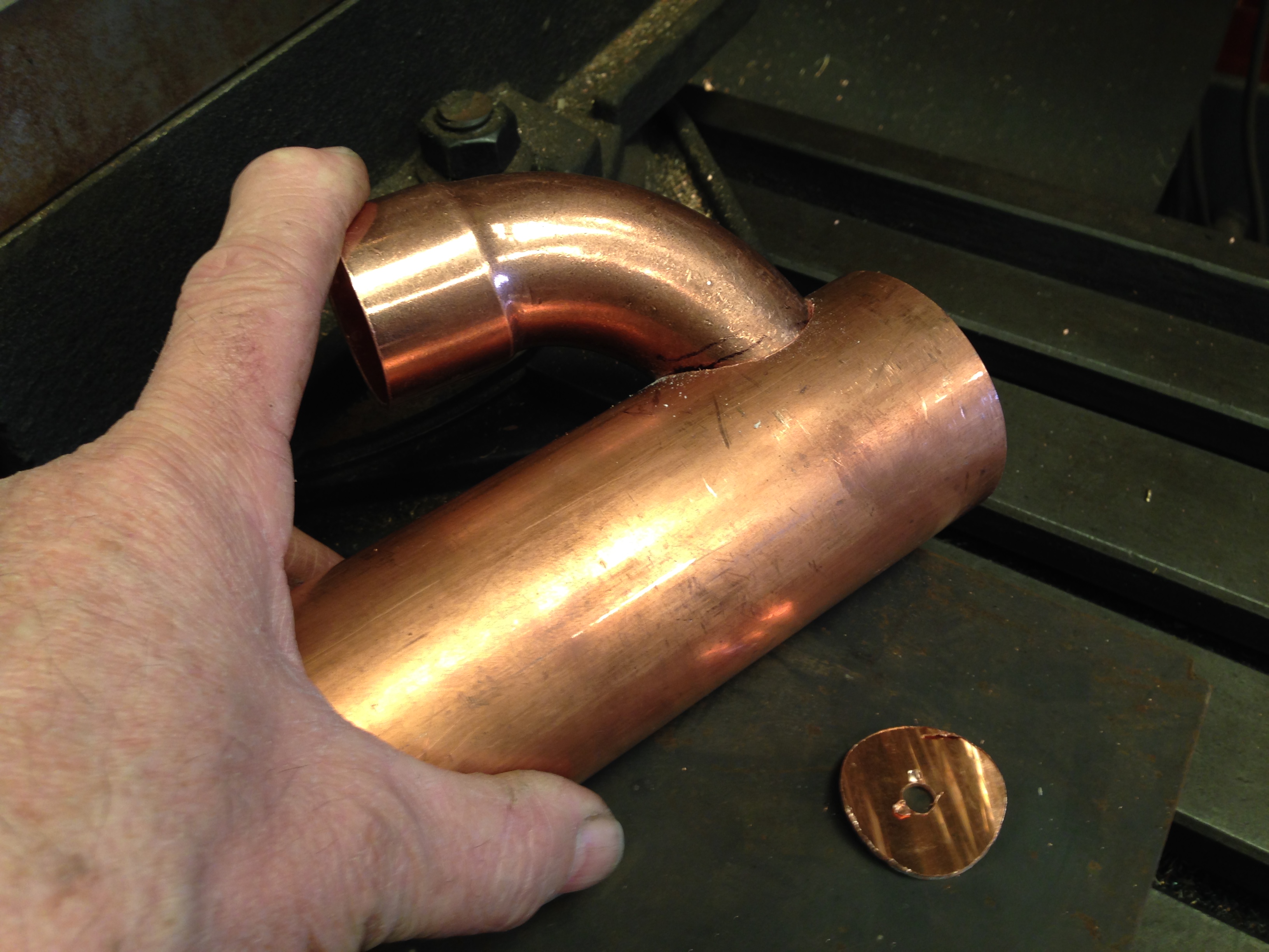
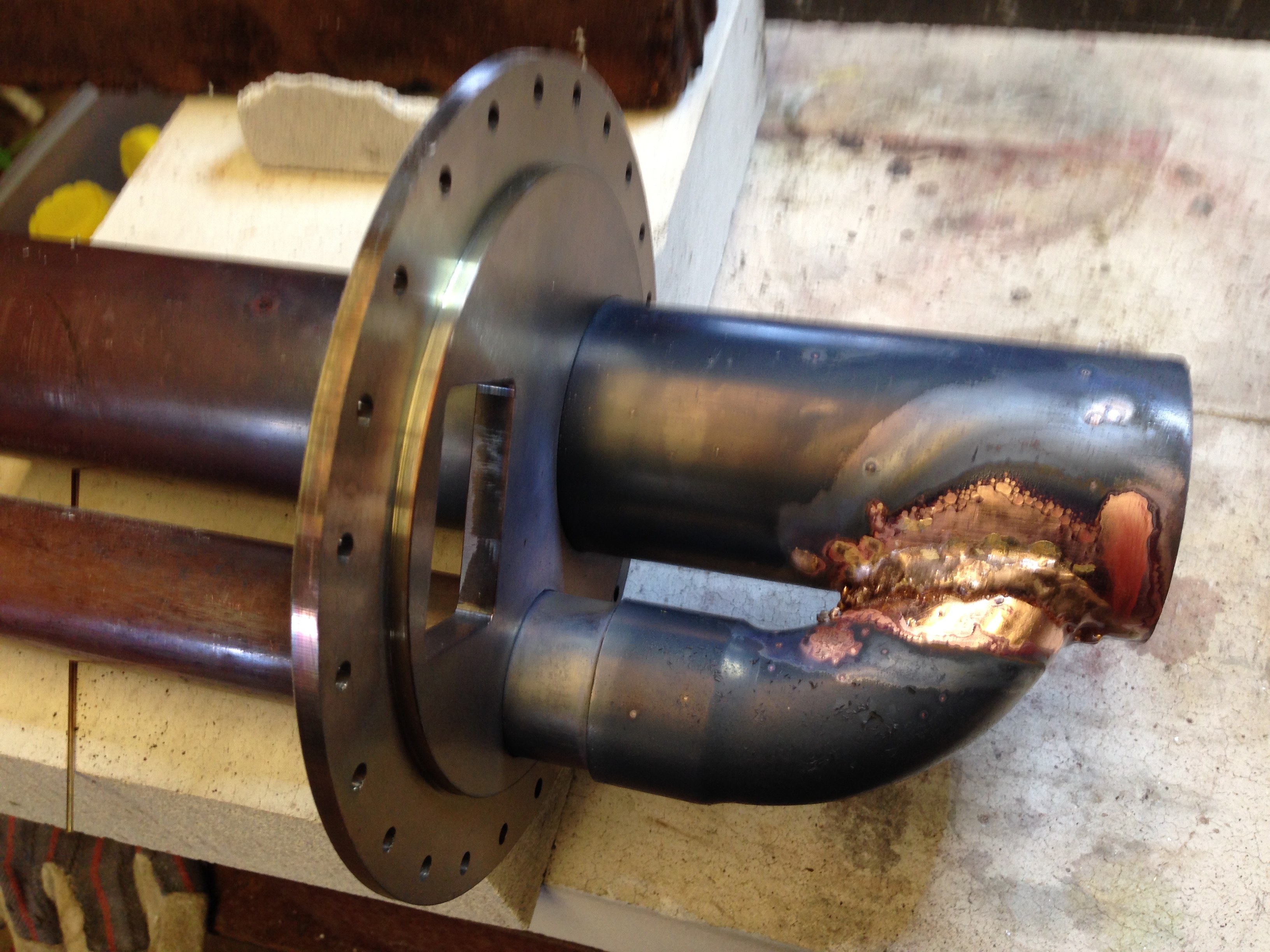
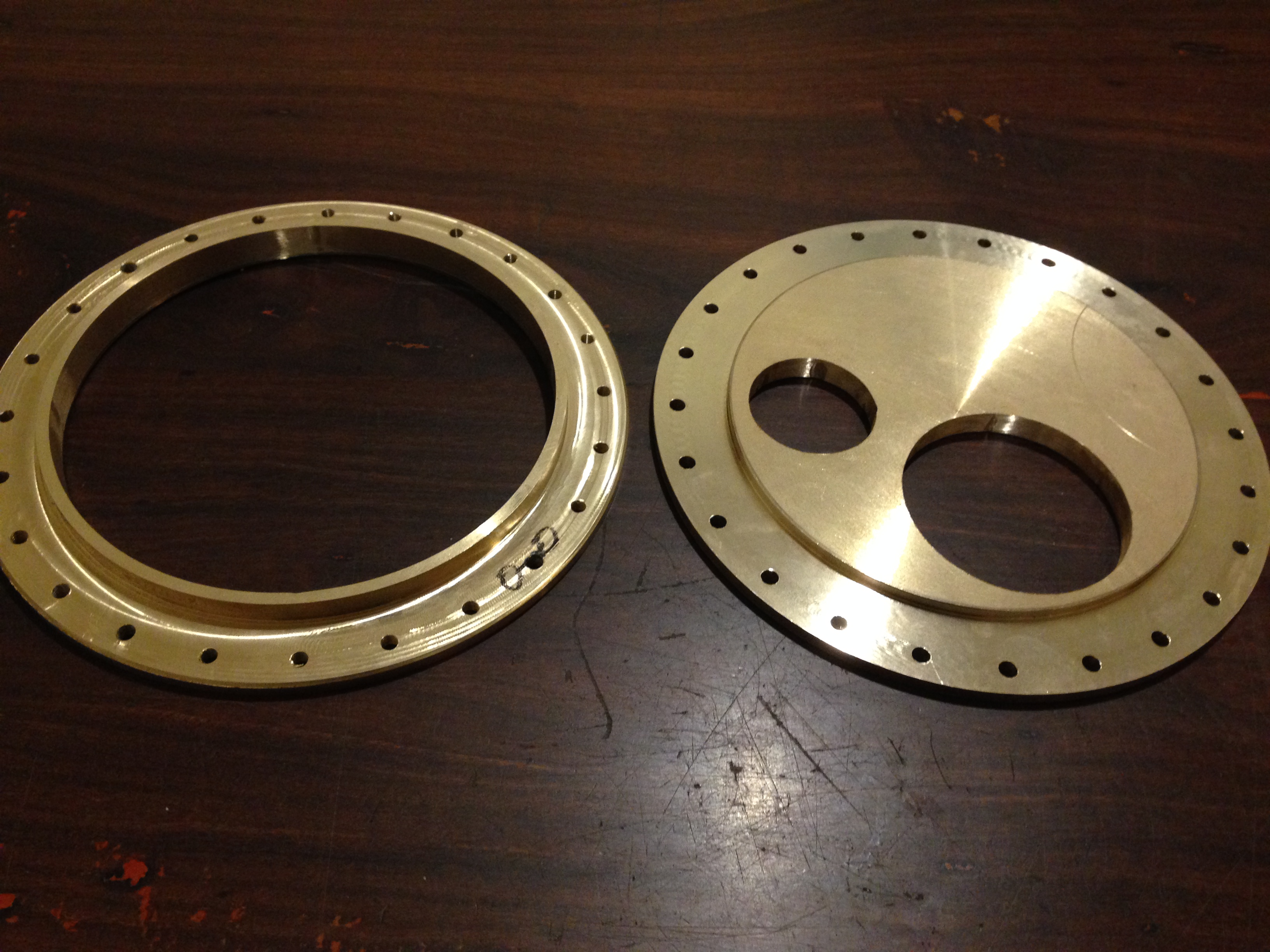
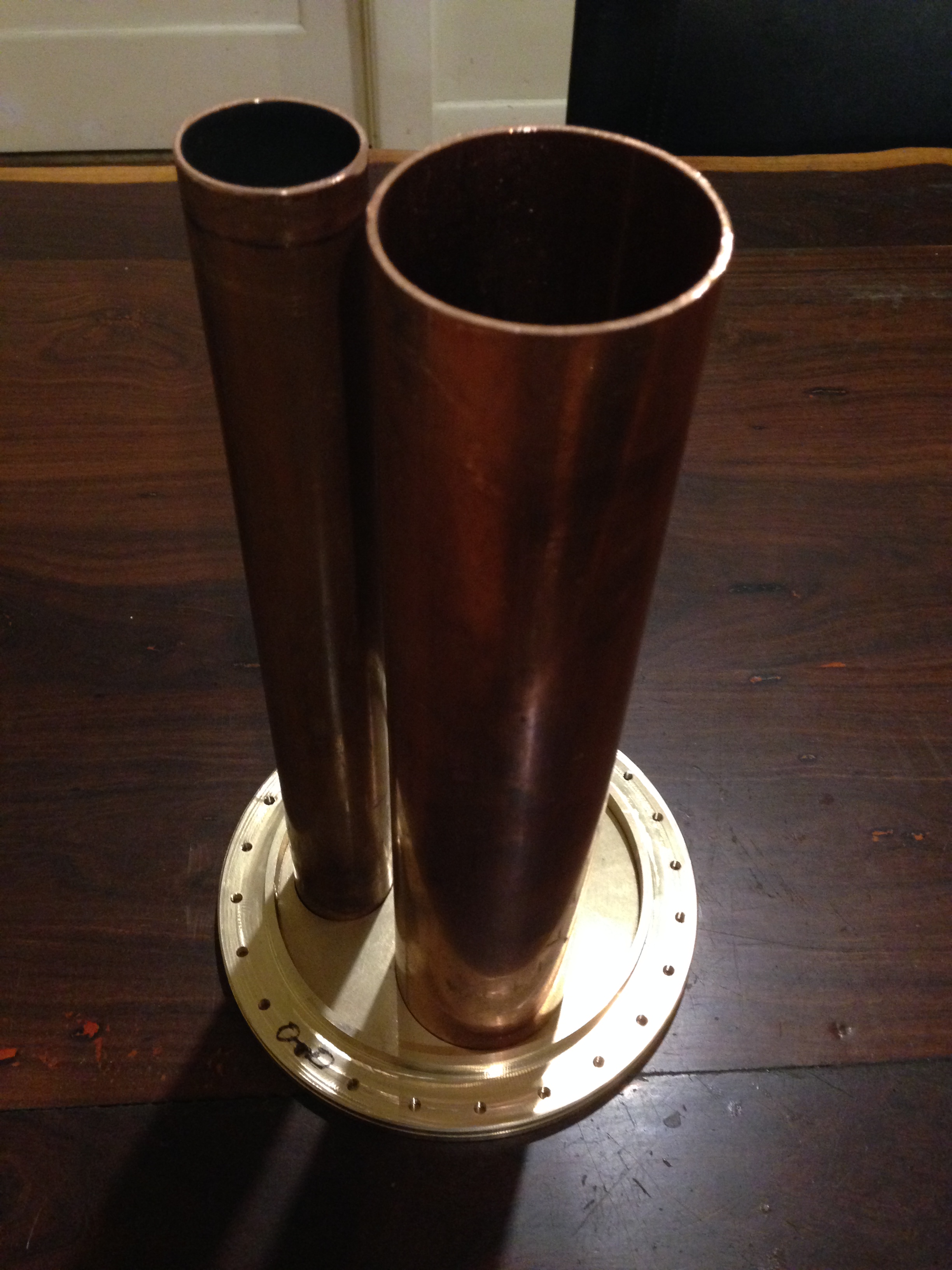
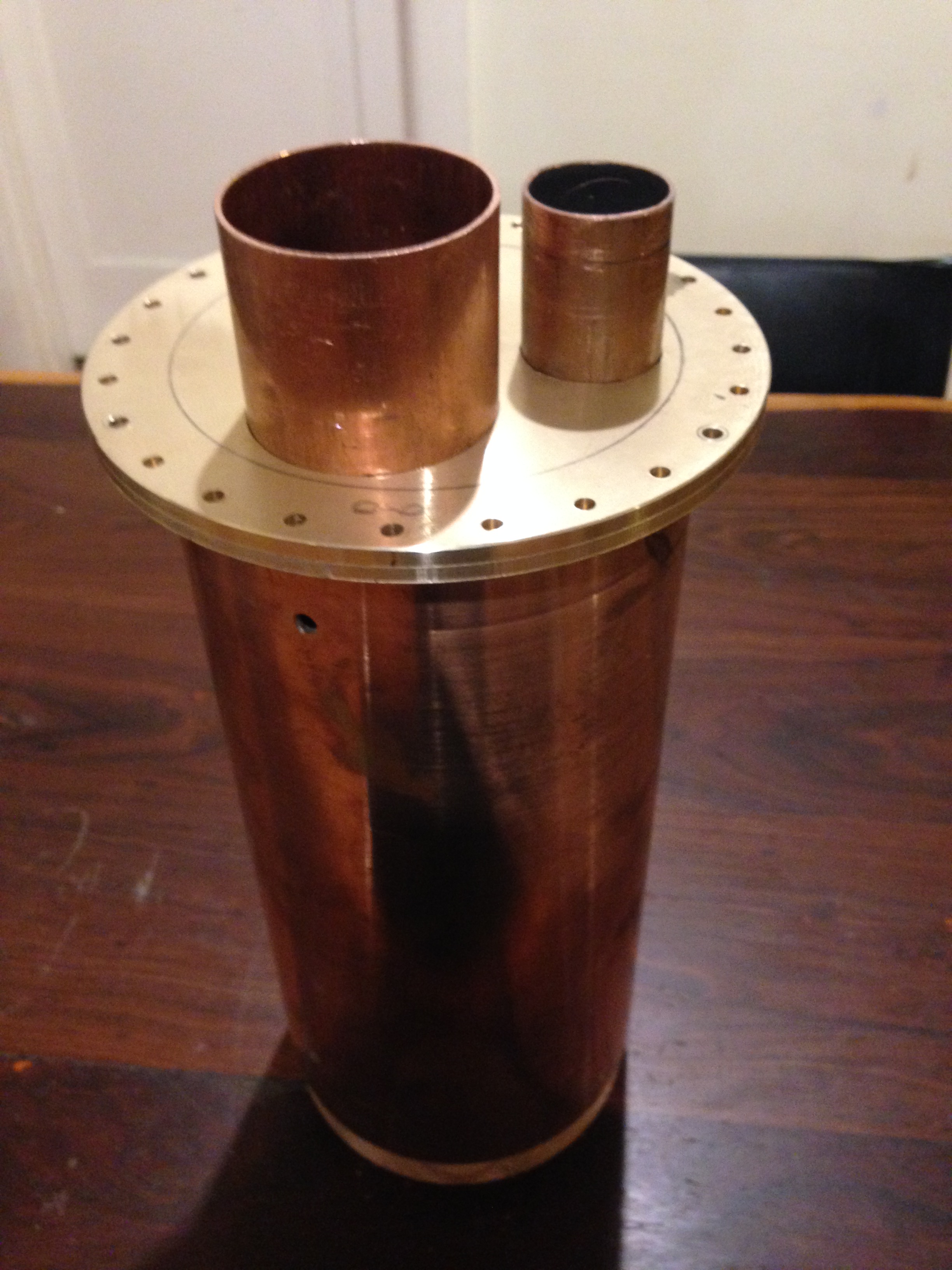
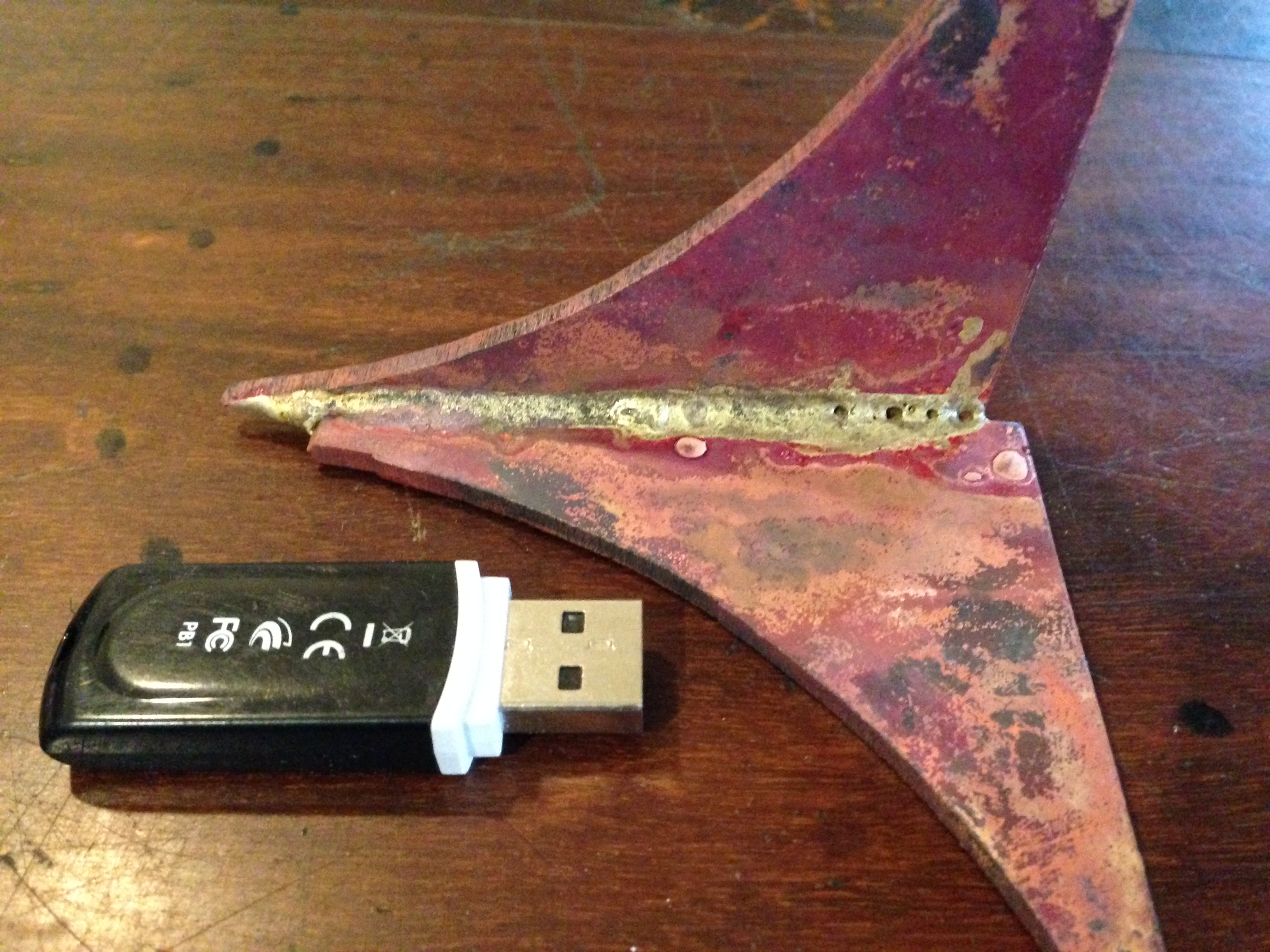
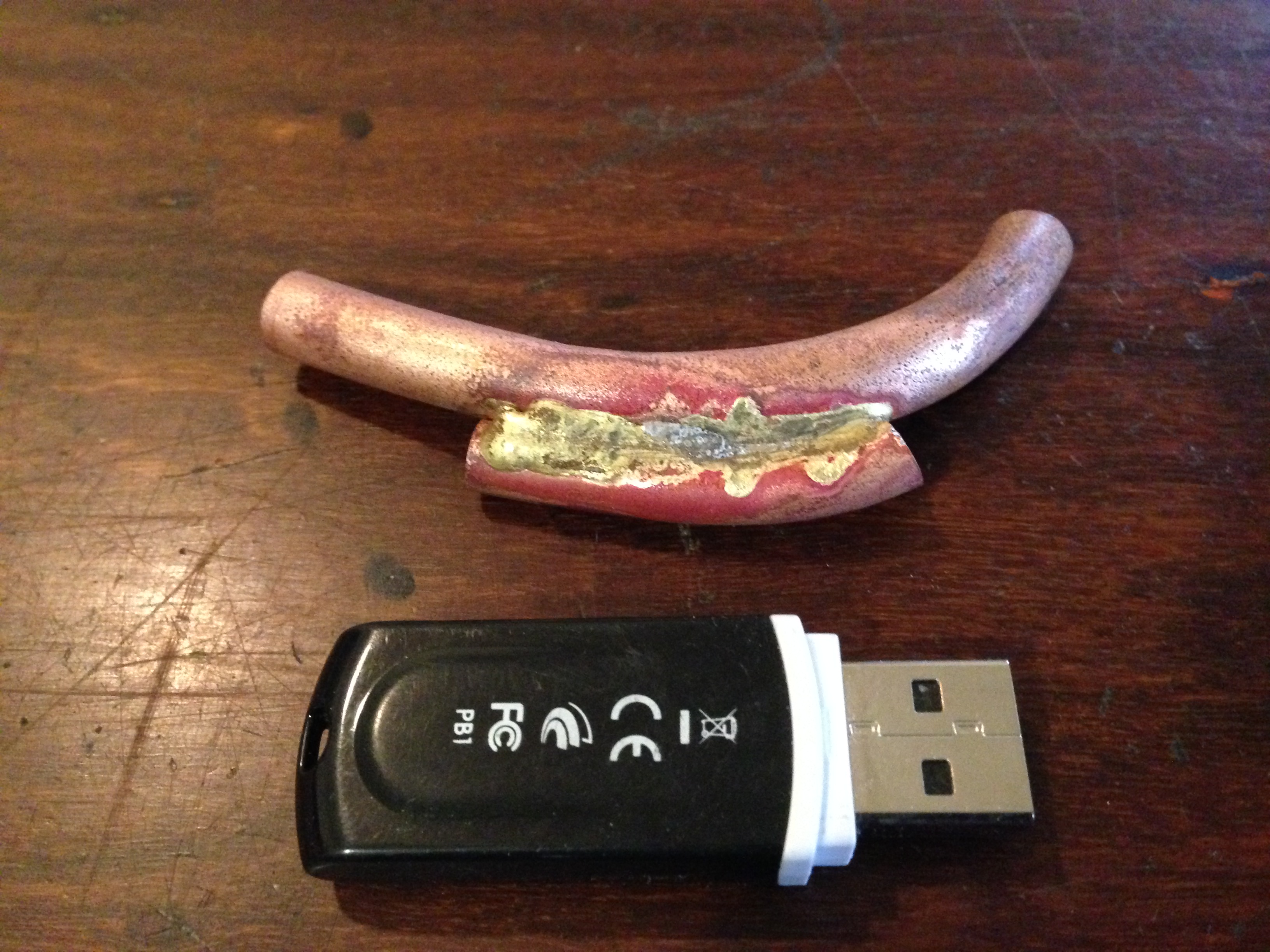
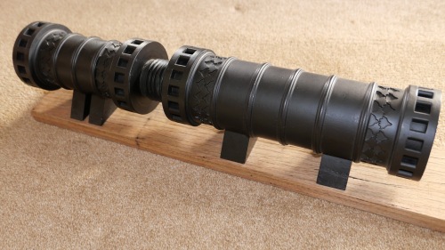
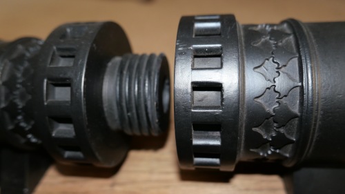
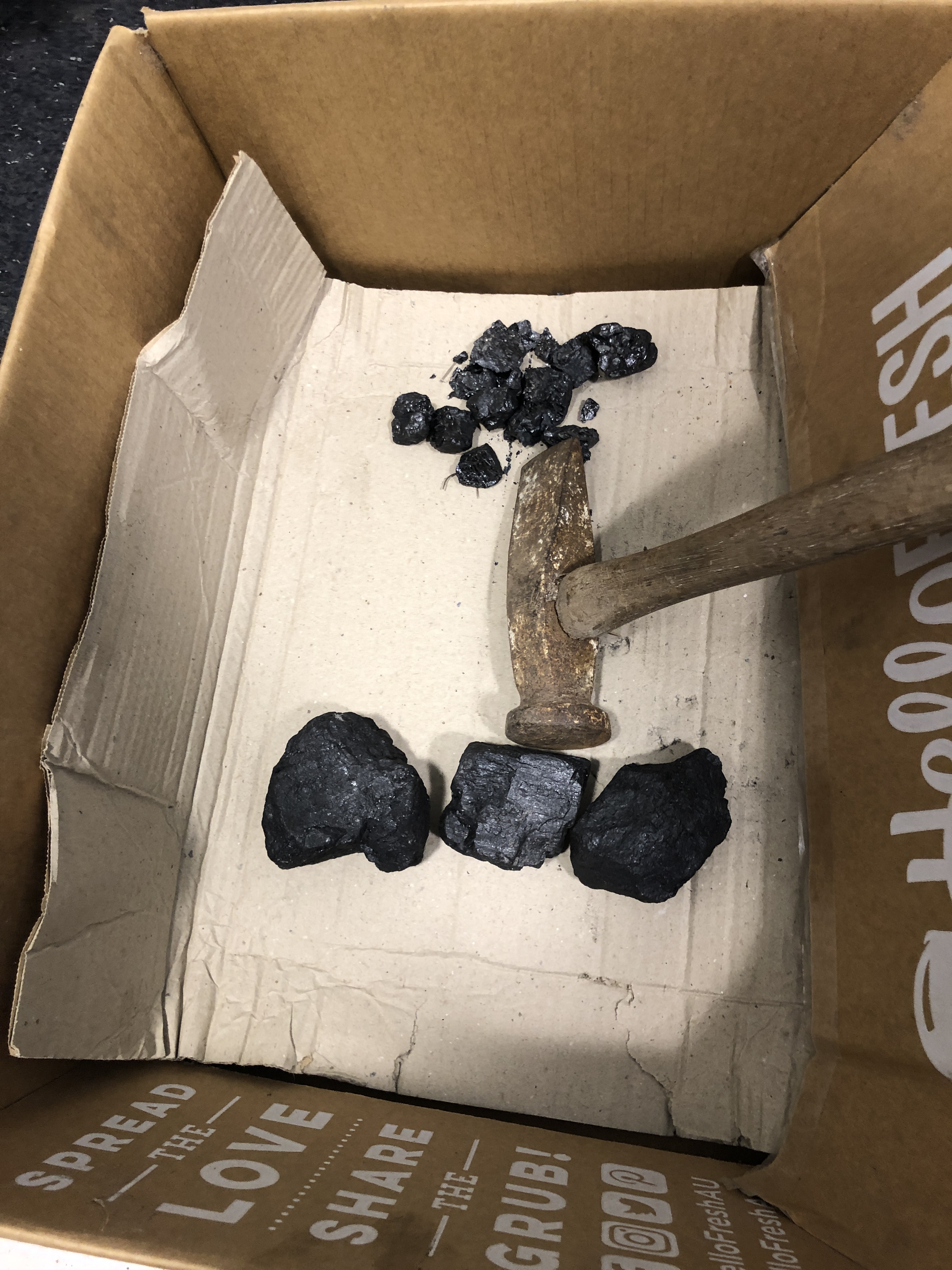
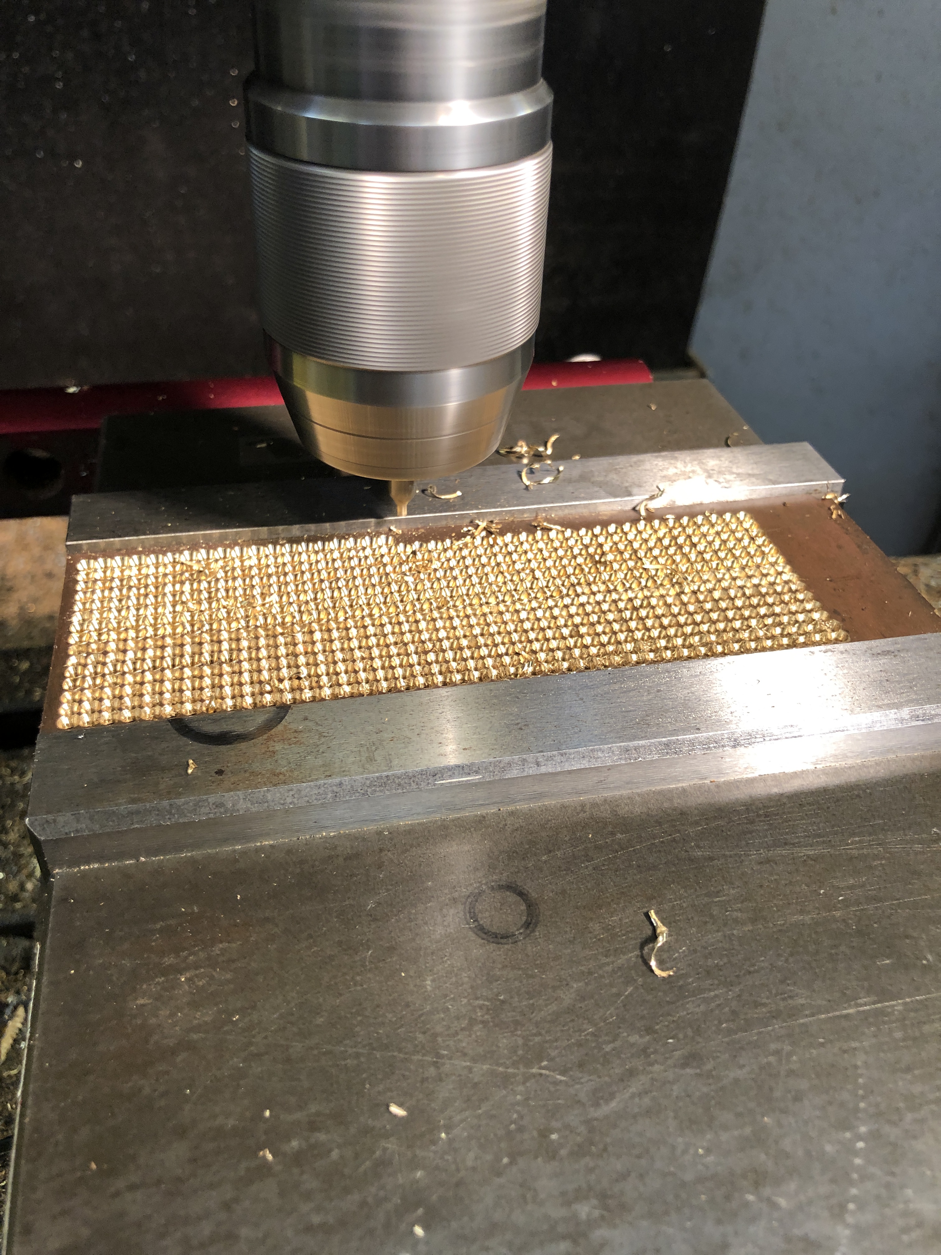
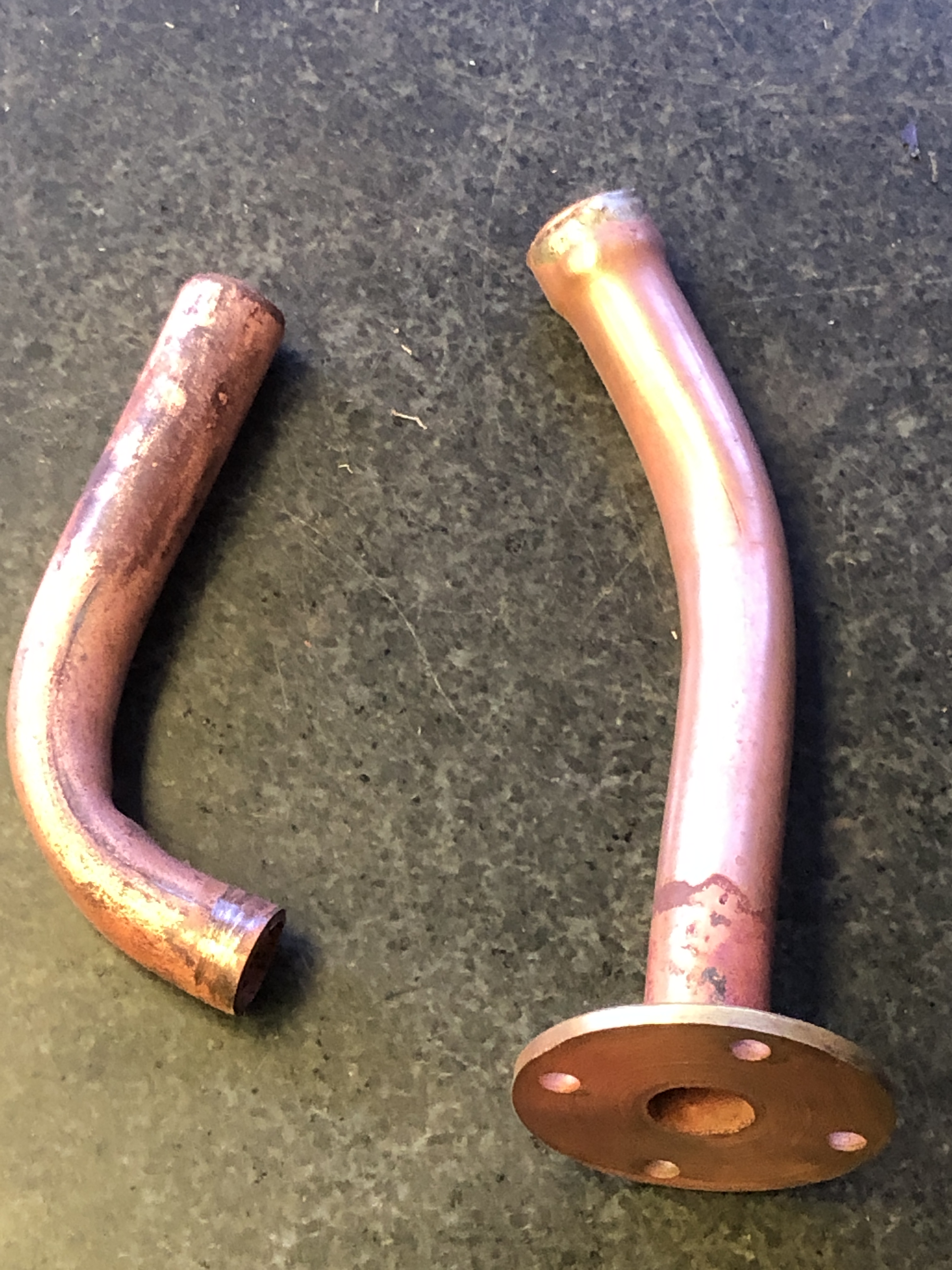
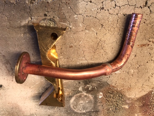
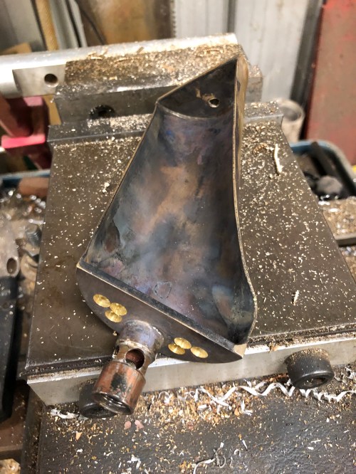
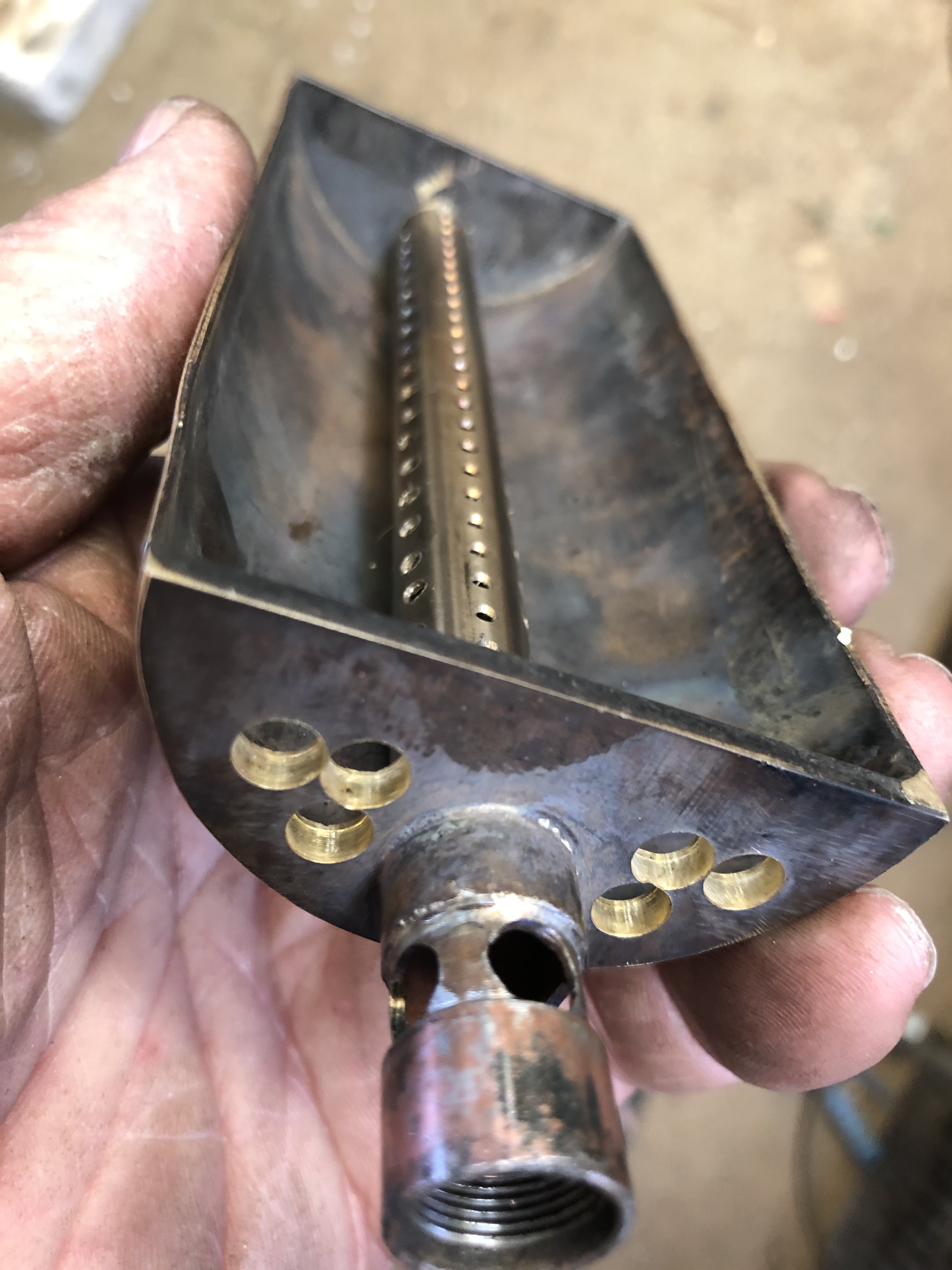
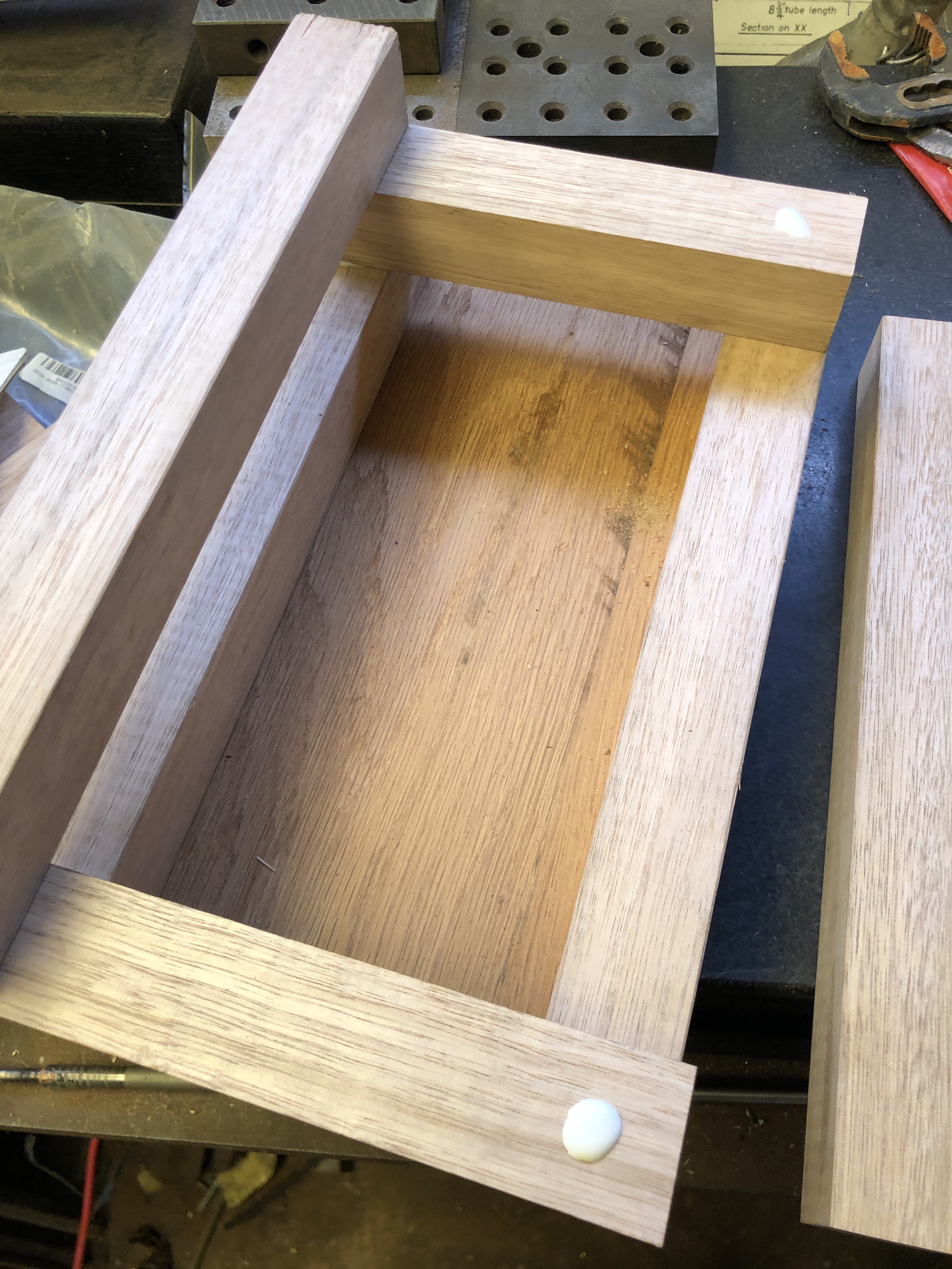
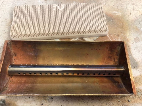
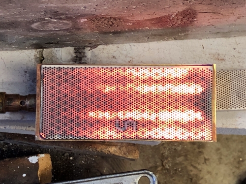
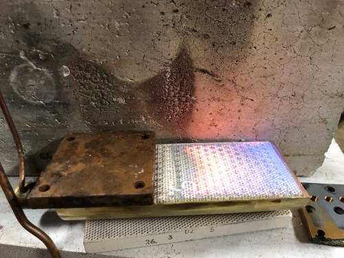
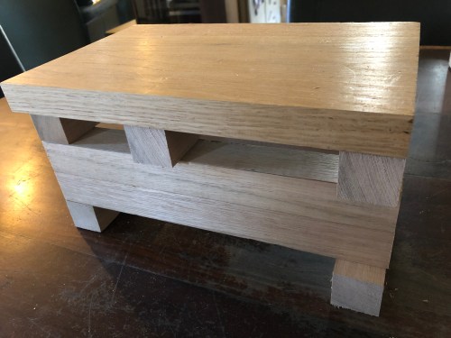
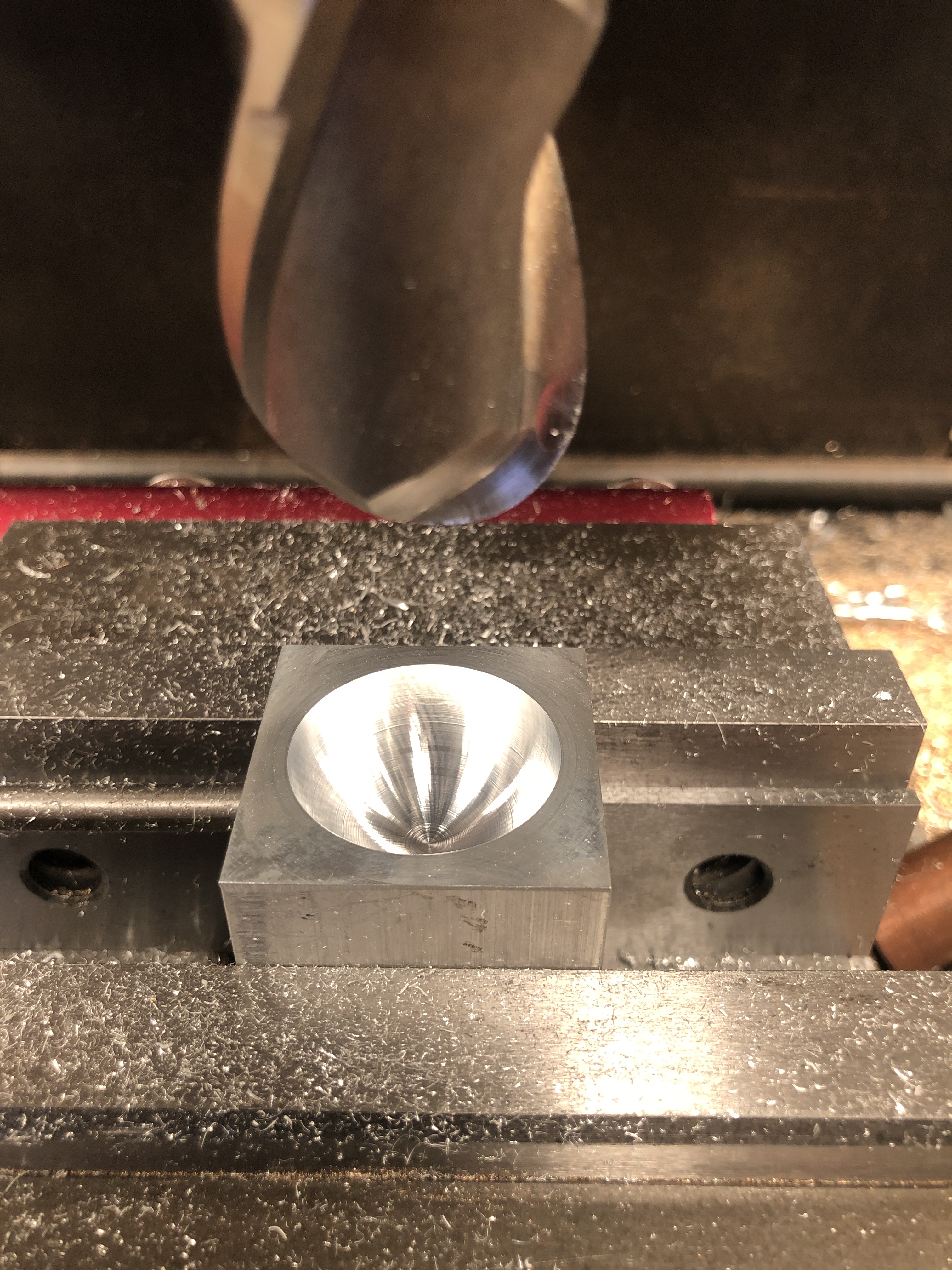
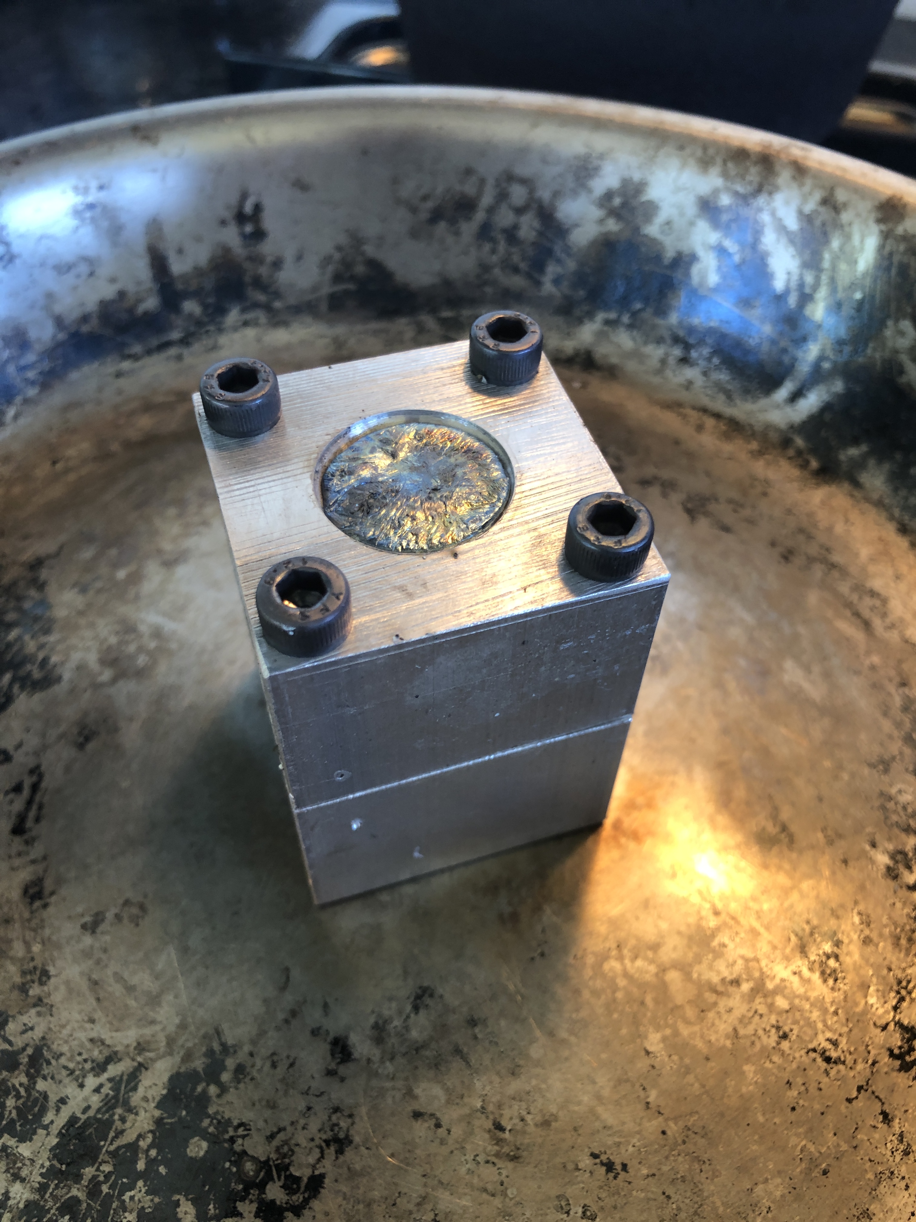
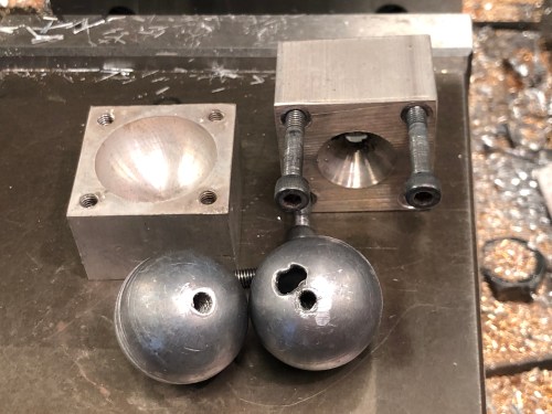
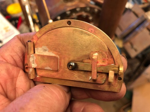
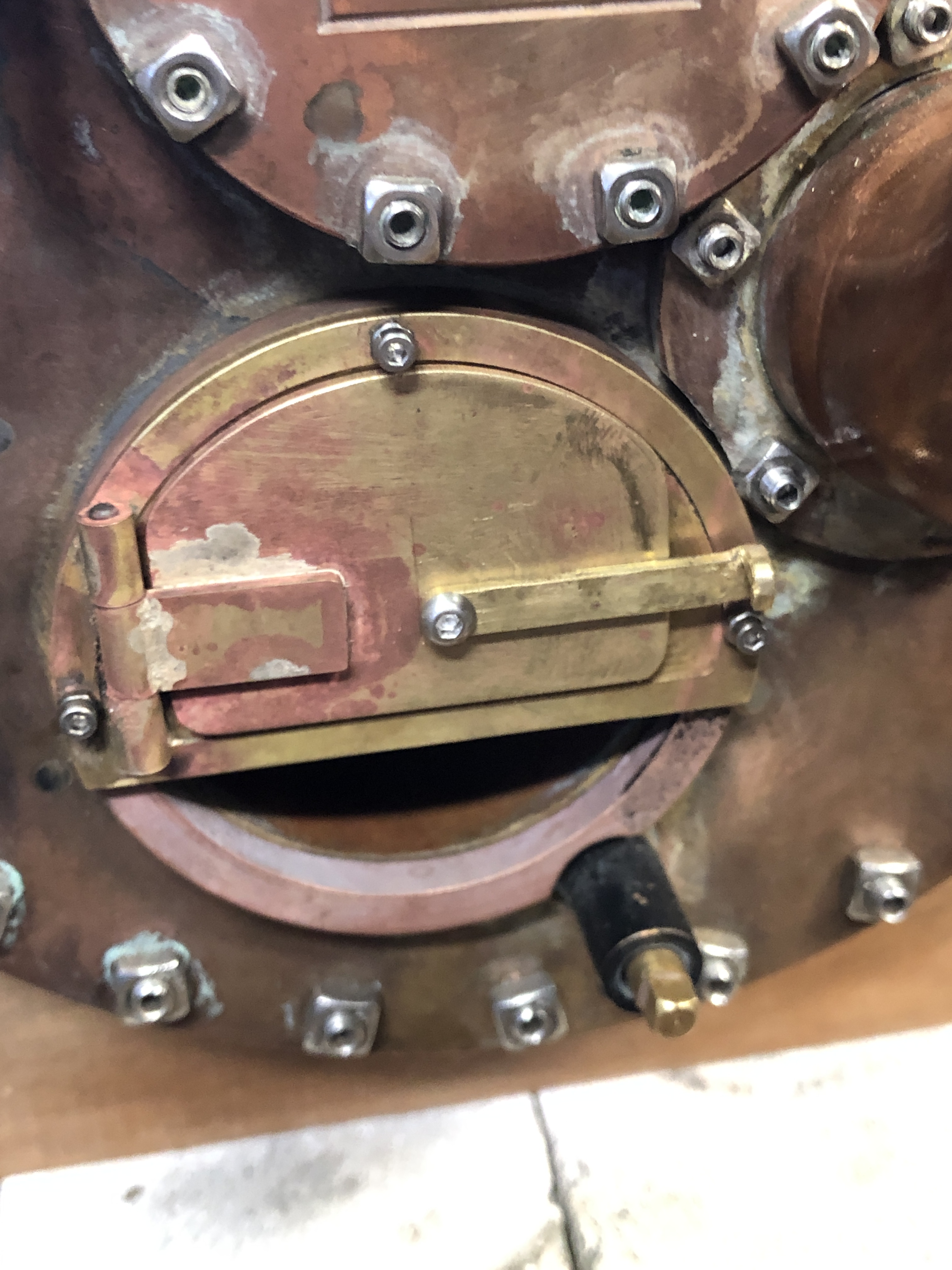
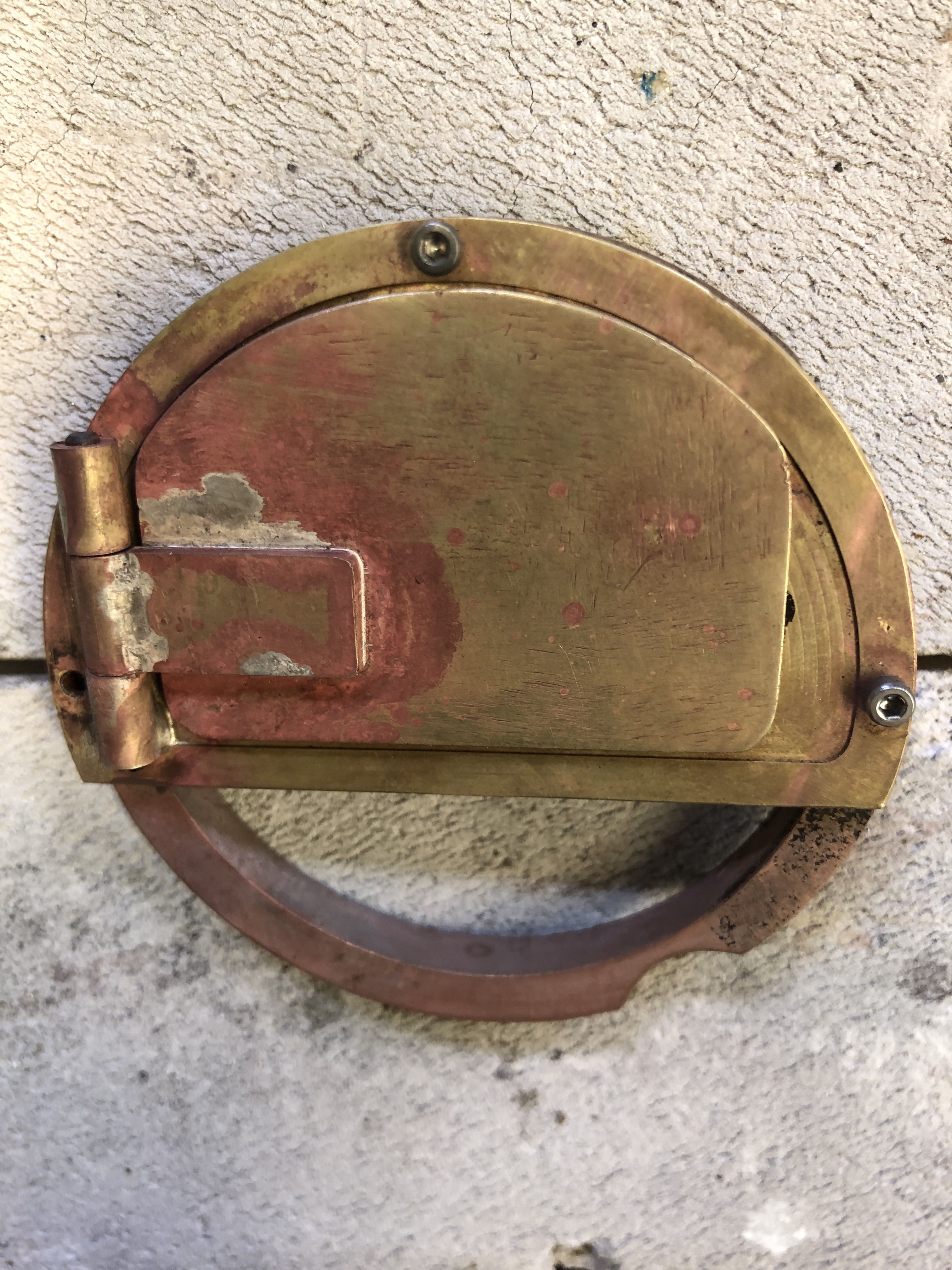
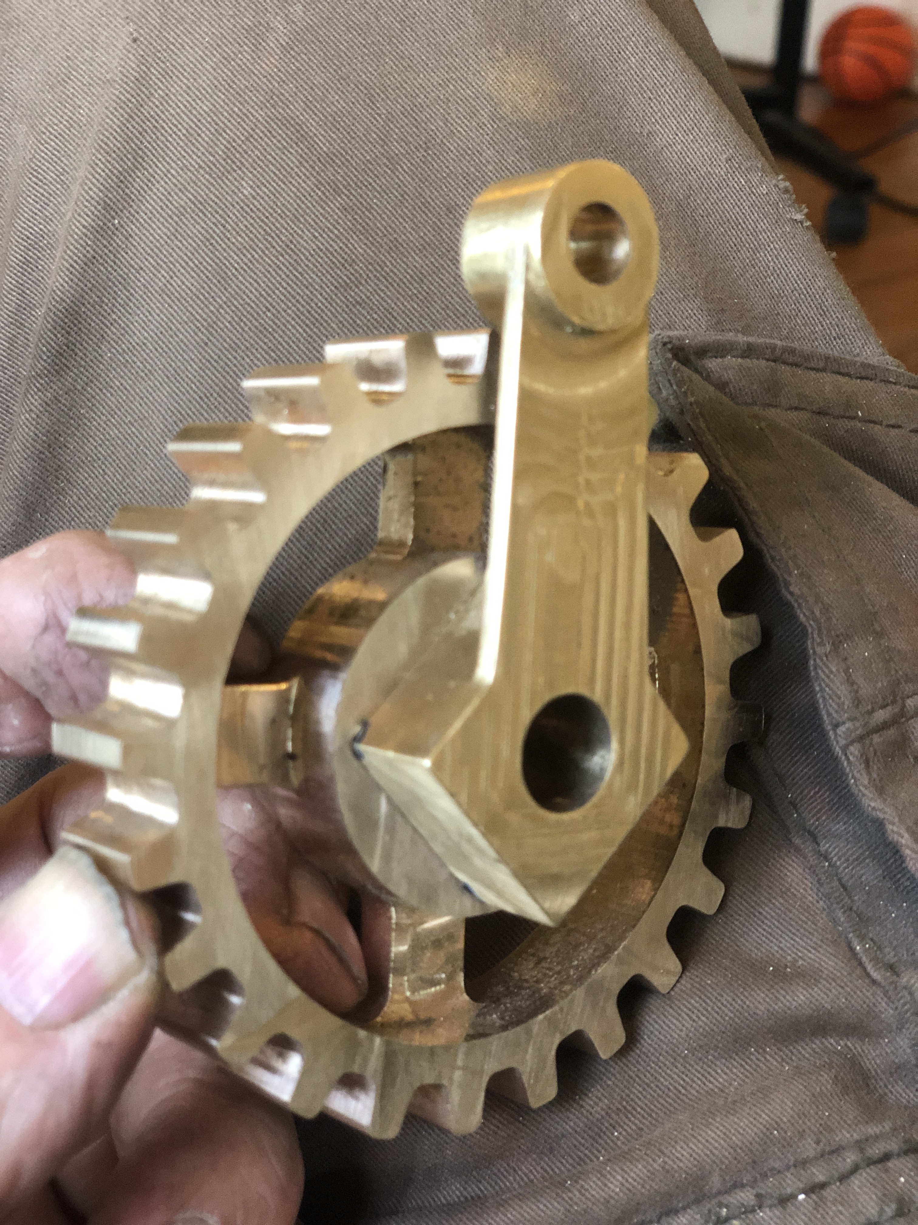
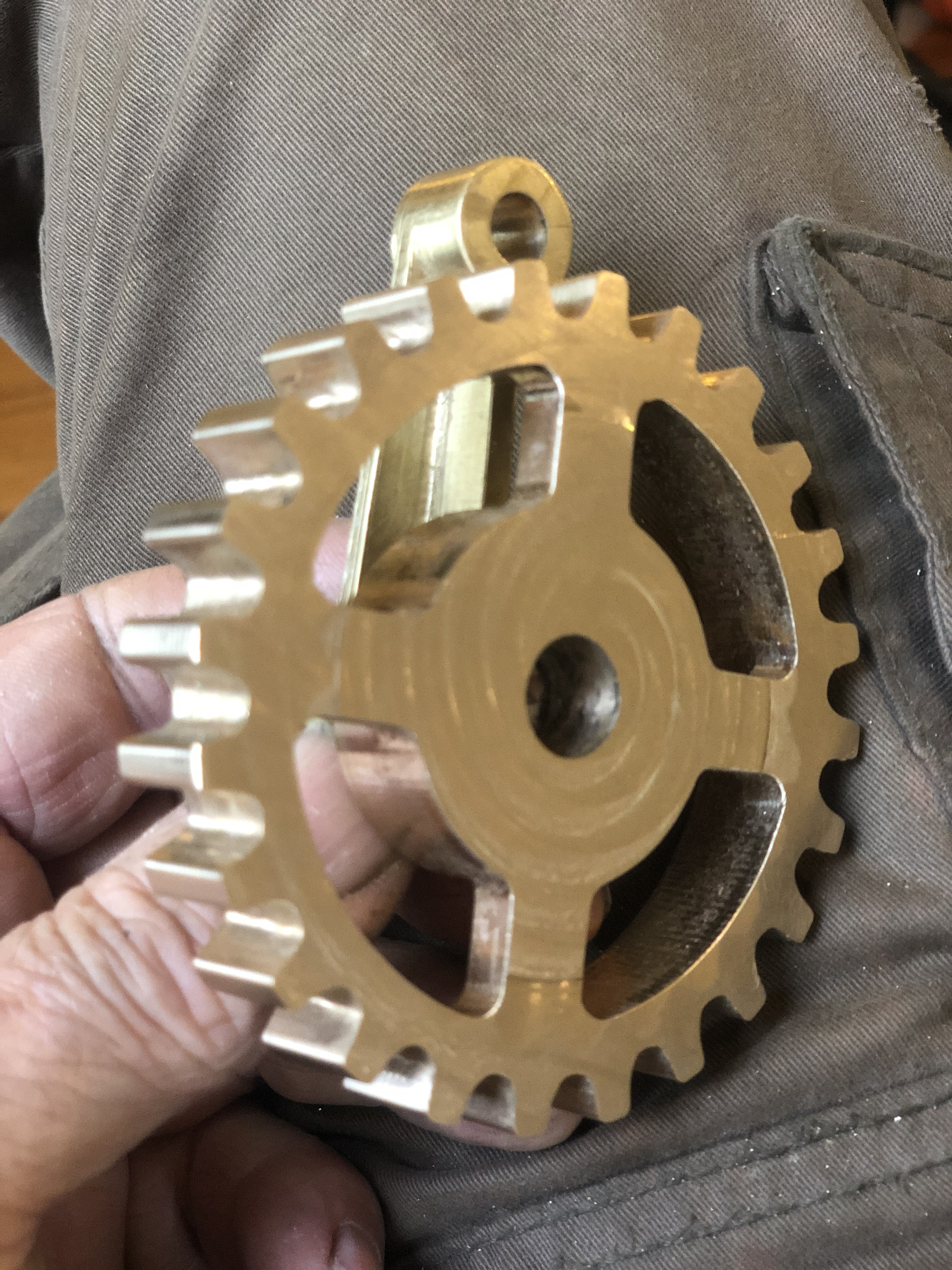
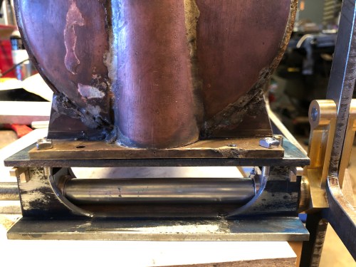
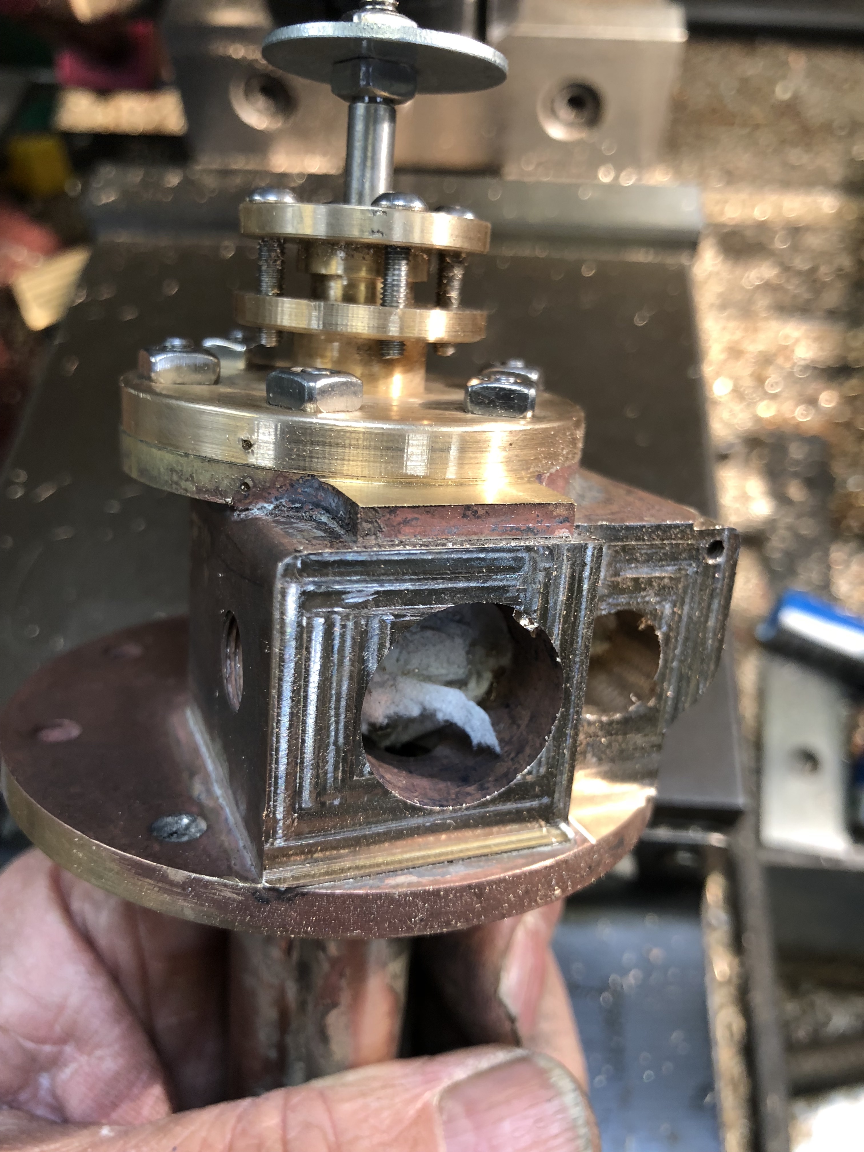
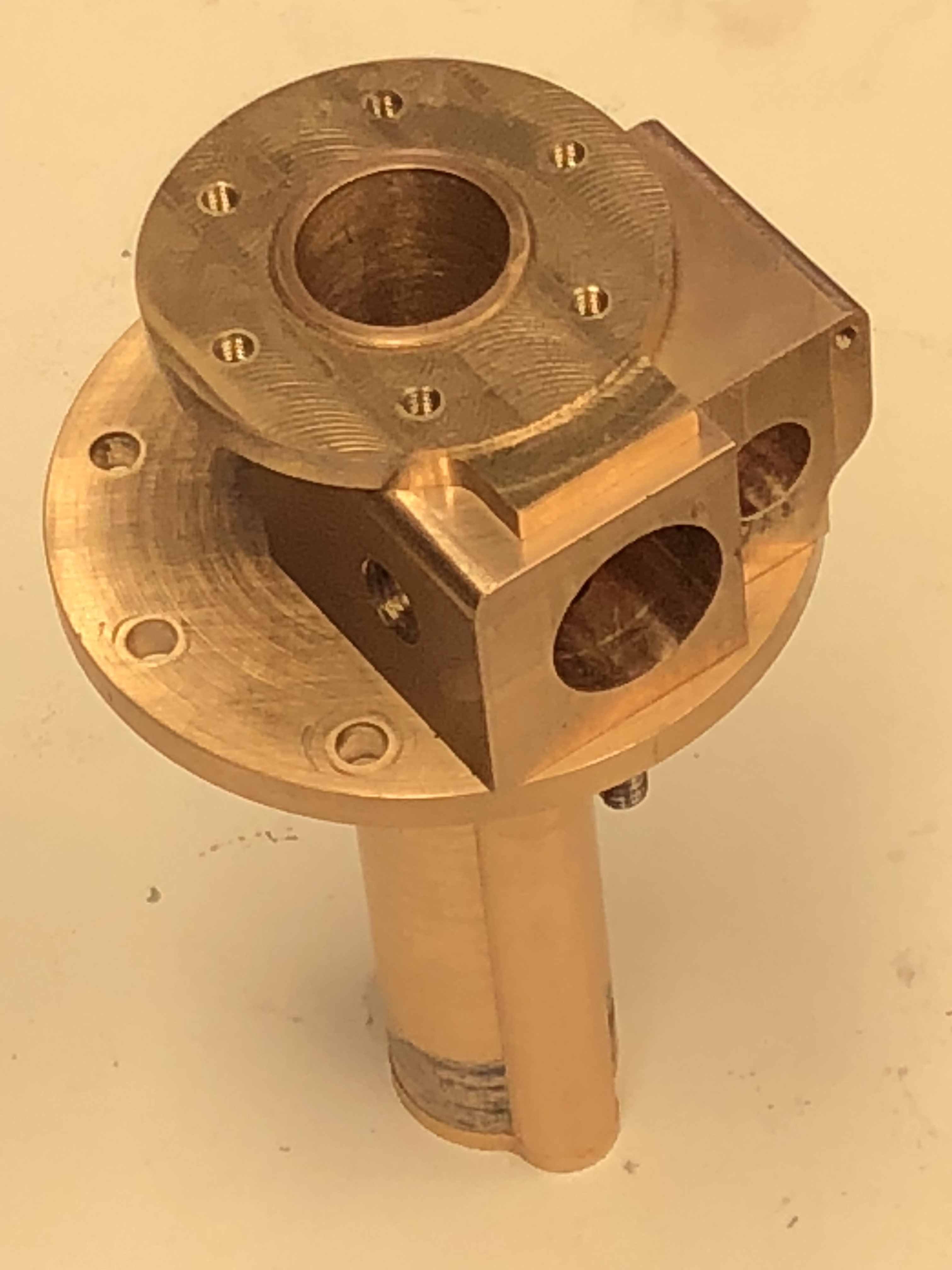
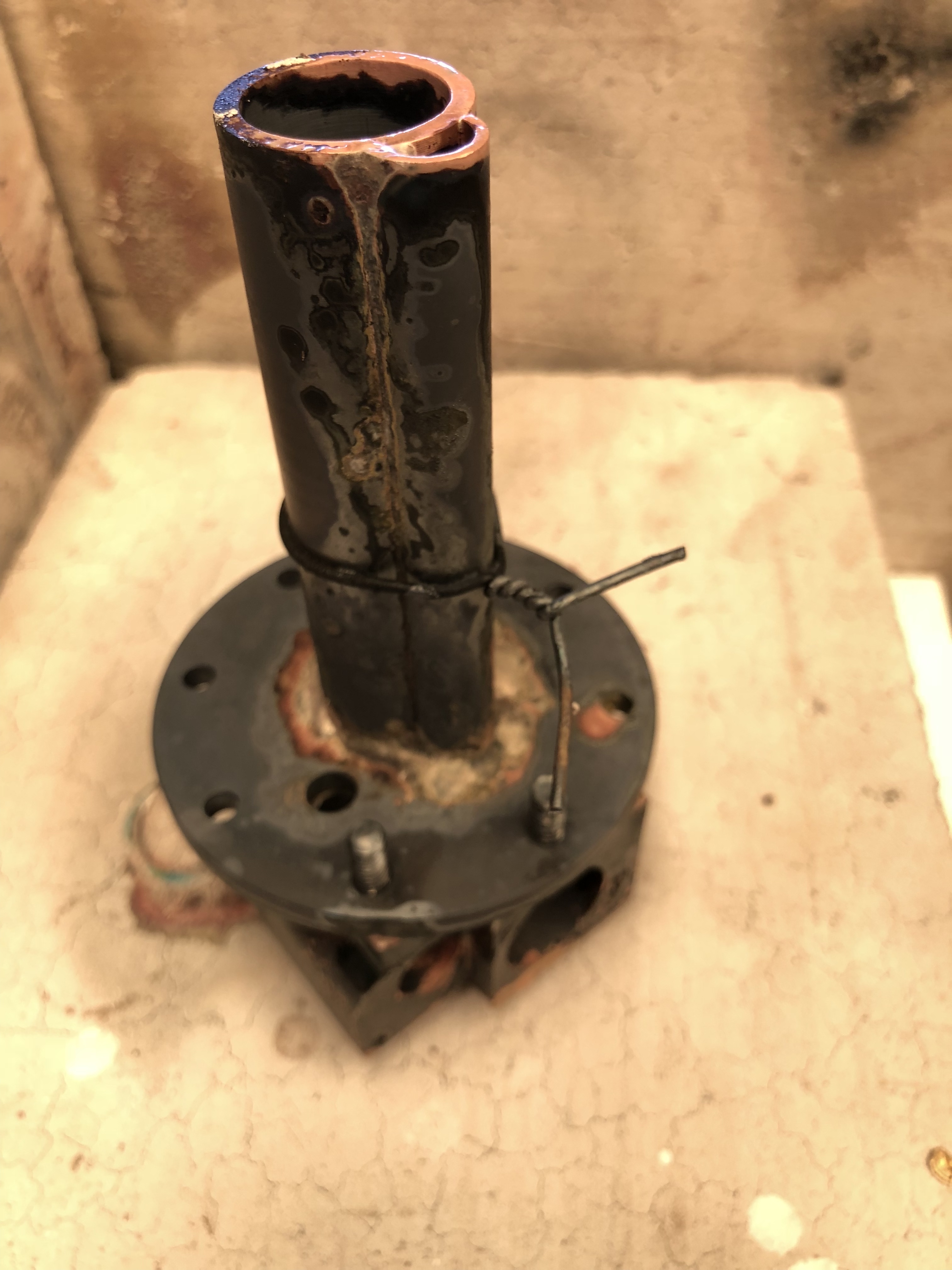
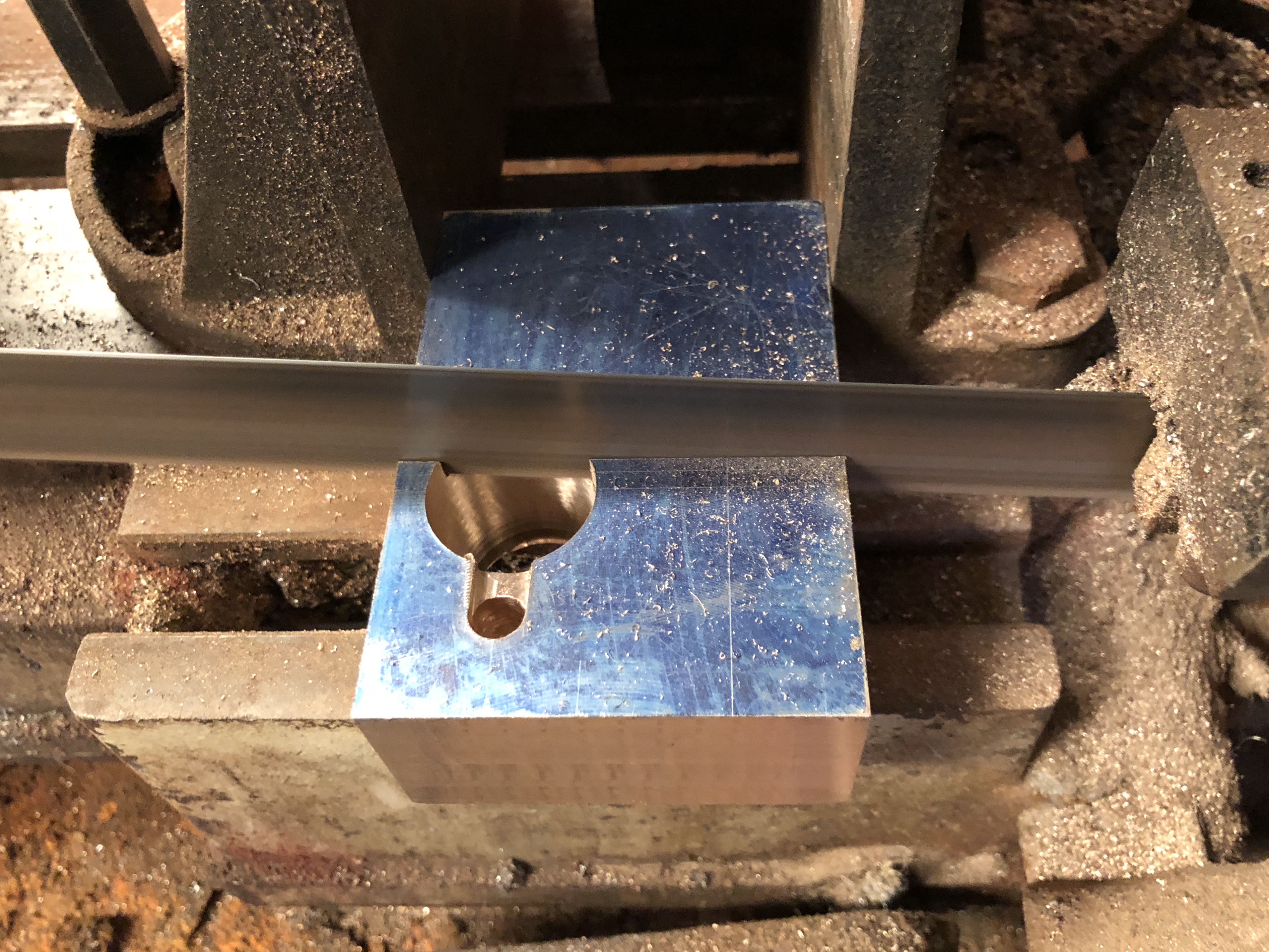
Here are the results of my first efforts.

Braze1.JPG

The copper is 3mm thick.  The bronze filler is not pretty, but this is my first ever effort.  I discovered that you cannot actually see the molten puddle until you have moved on a bit, and by then it is easy to have applied too much filler.

braze5.JPG

I cut across the join to check the adequacy of the brazed join.  I was quite pleased to see that there were no gaps or voids.  Also, although the bronze filler looks ugly on the surface, it is actually fairly flat, and should be insignificant when painted.   You can see the V which was prepared in the edges of the join.

Braze2.JPG

Next I tried an angle join.  Looks neater, but not enough bronze filler at one end.  USB for scale.

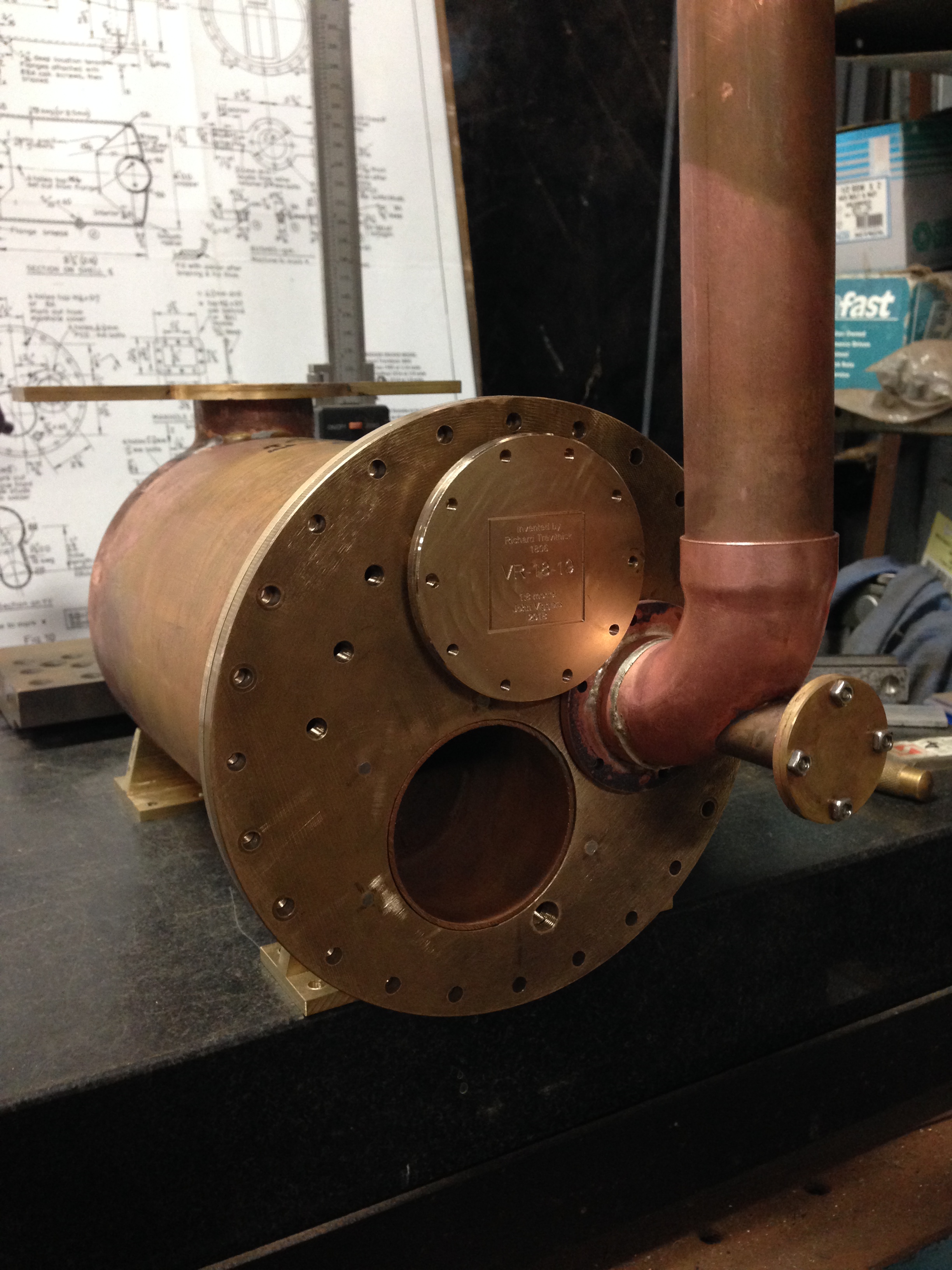
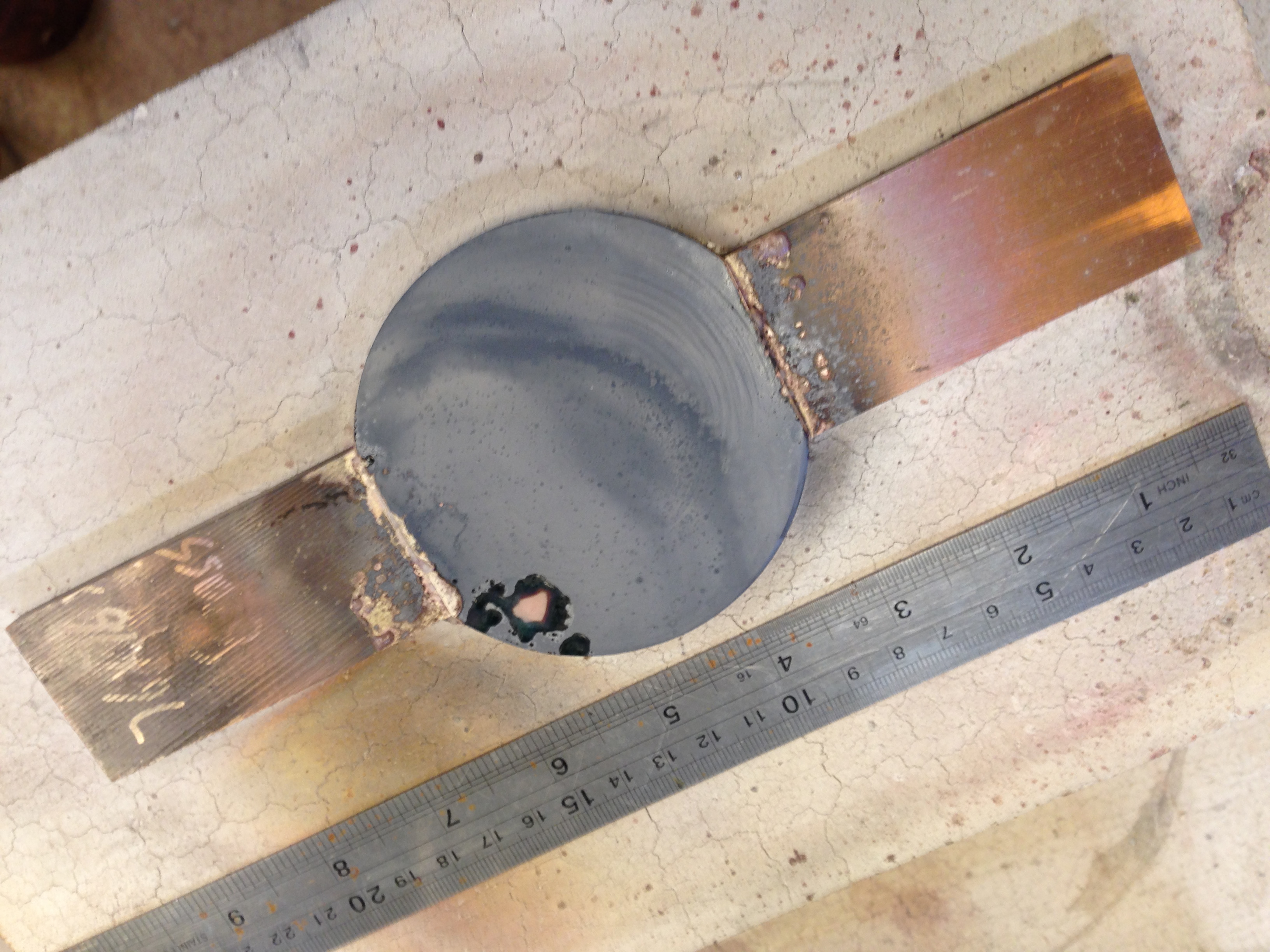
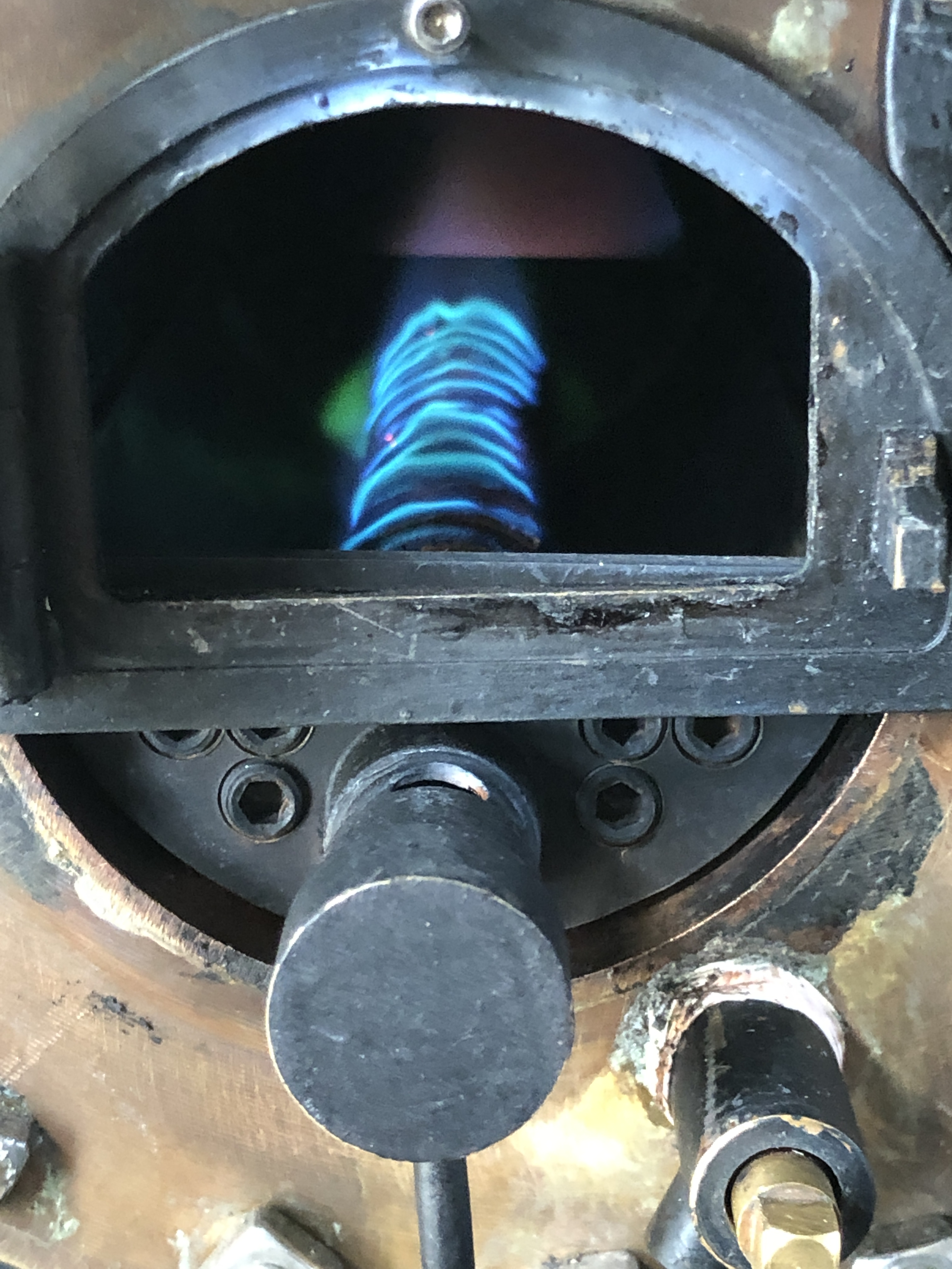
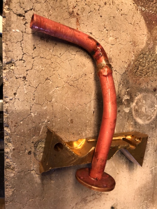
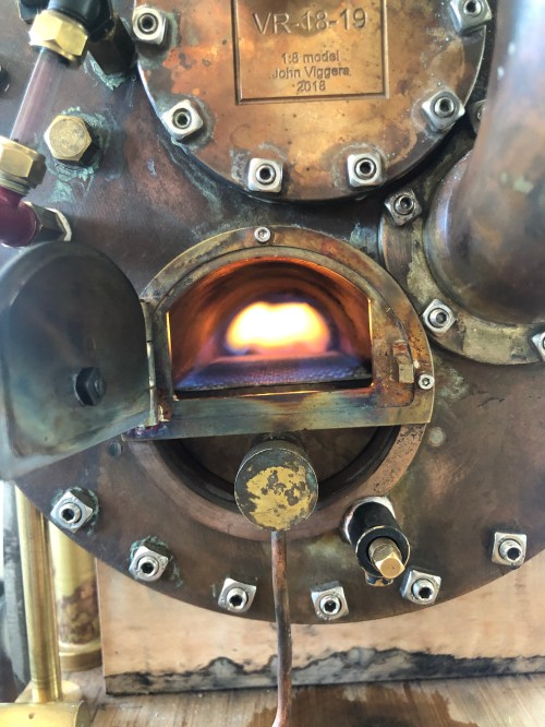
OK, looking promising, but what about thin copper?  Will that just melt away?  By the way, my heat source is oxy-acetylene.  I tried MAP gas with air, but got nowhere near enough heat.  Oxy-acetylene burns at 3500ºc and copper melts at 1083ºc so it is not difficult to end up with an ugly, expensive blob of copper and bronze.

braze3.JPG

This is 1/4″ pipe with a 0.7mm wall.   No problemo.

braze4.JPG

and the final test for the day was end joining the 1/4″ pipe.  The hardest aspect was holding them in position.  Quite happy with this.

I tried both 1.6 and 2.4mm bronze filler rod diameters, and for this scale job I preferred the 1.6mm.  The  joins were significantly lumpier with the 2.4mm.

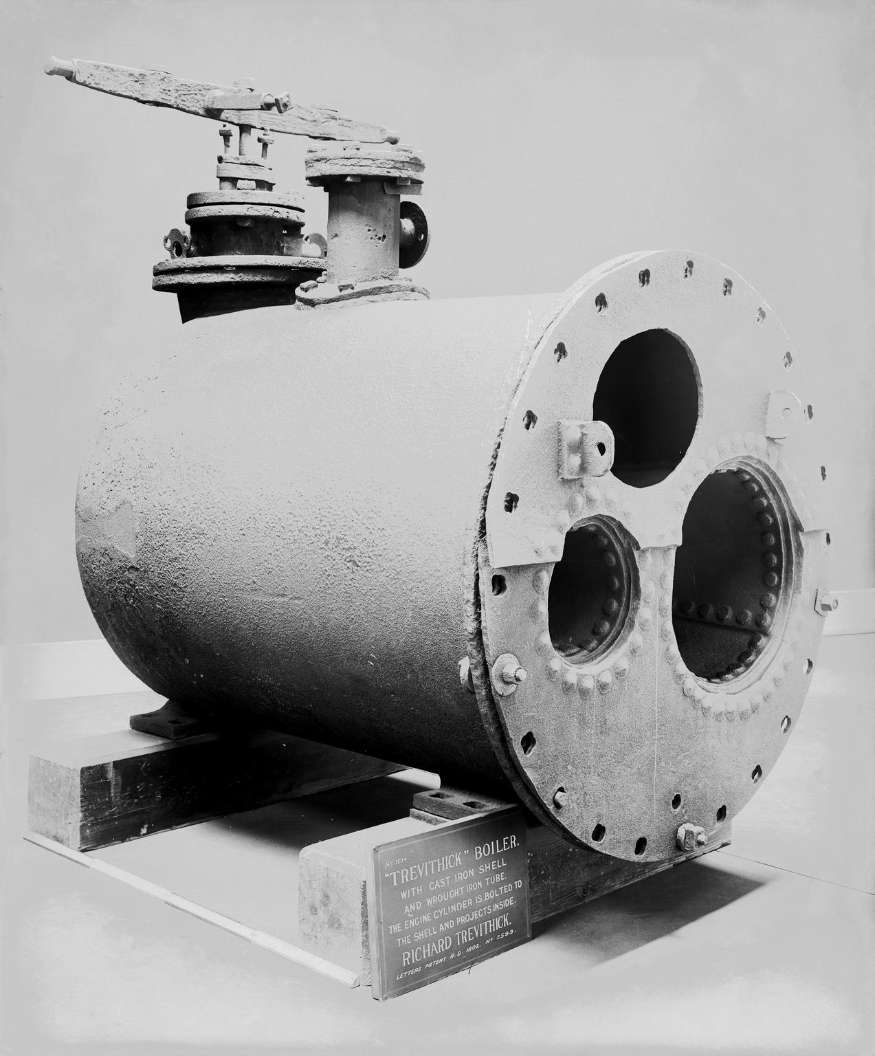
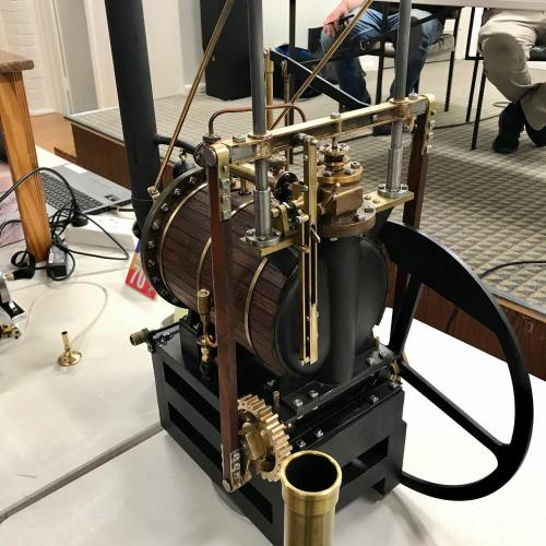
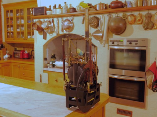
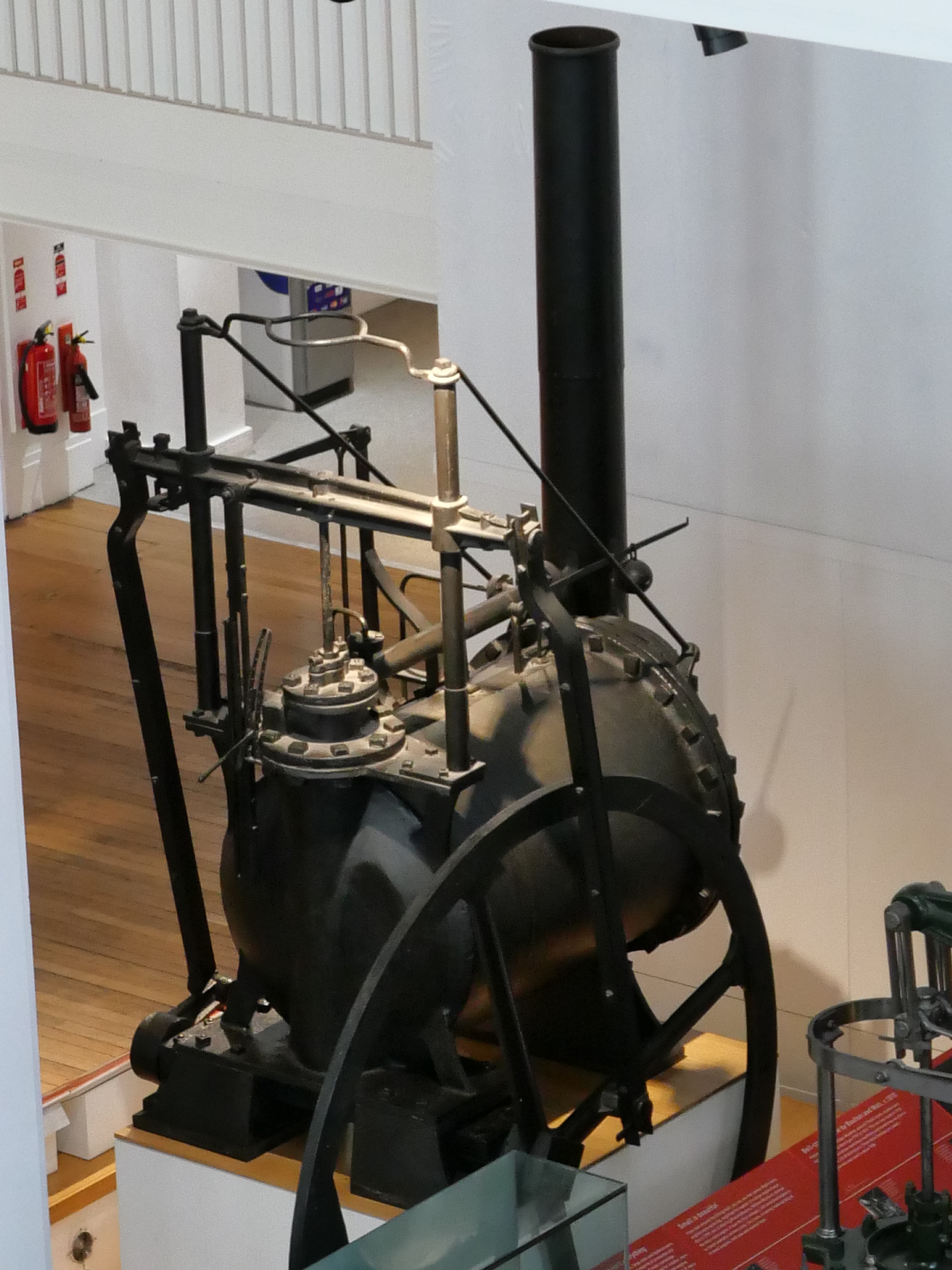
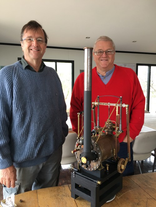
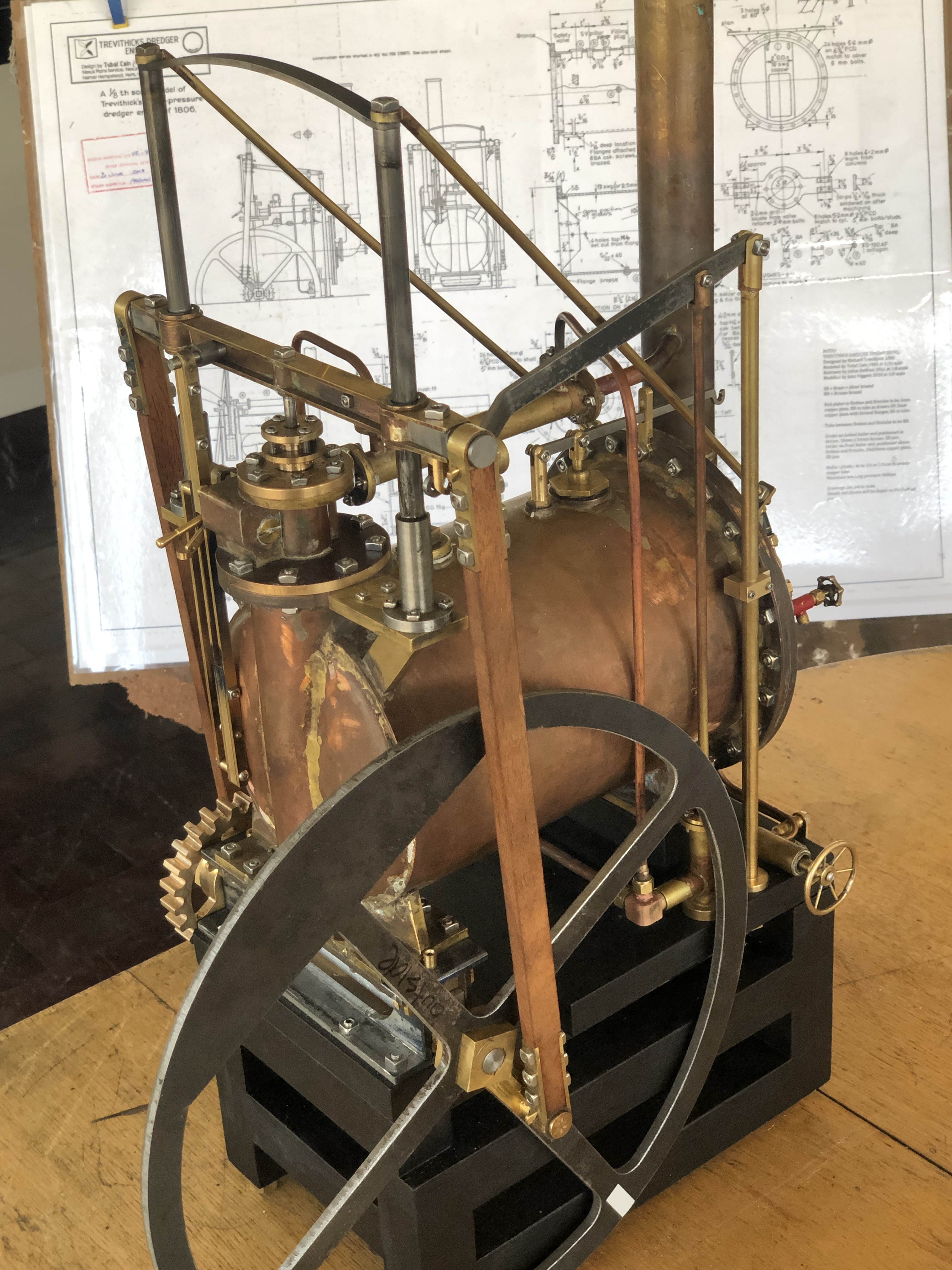
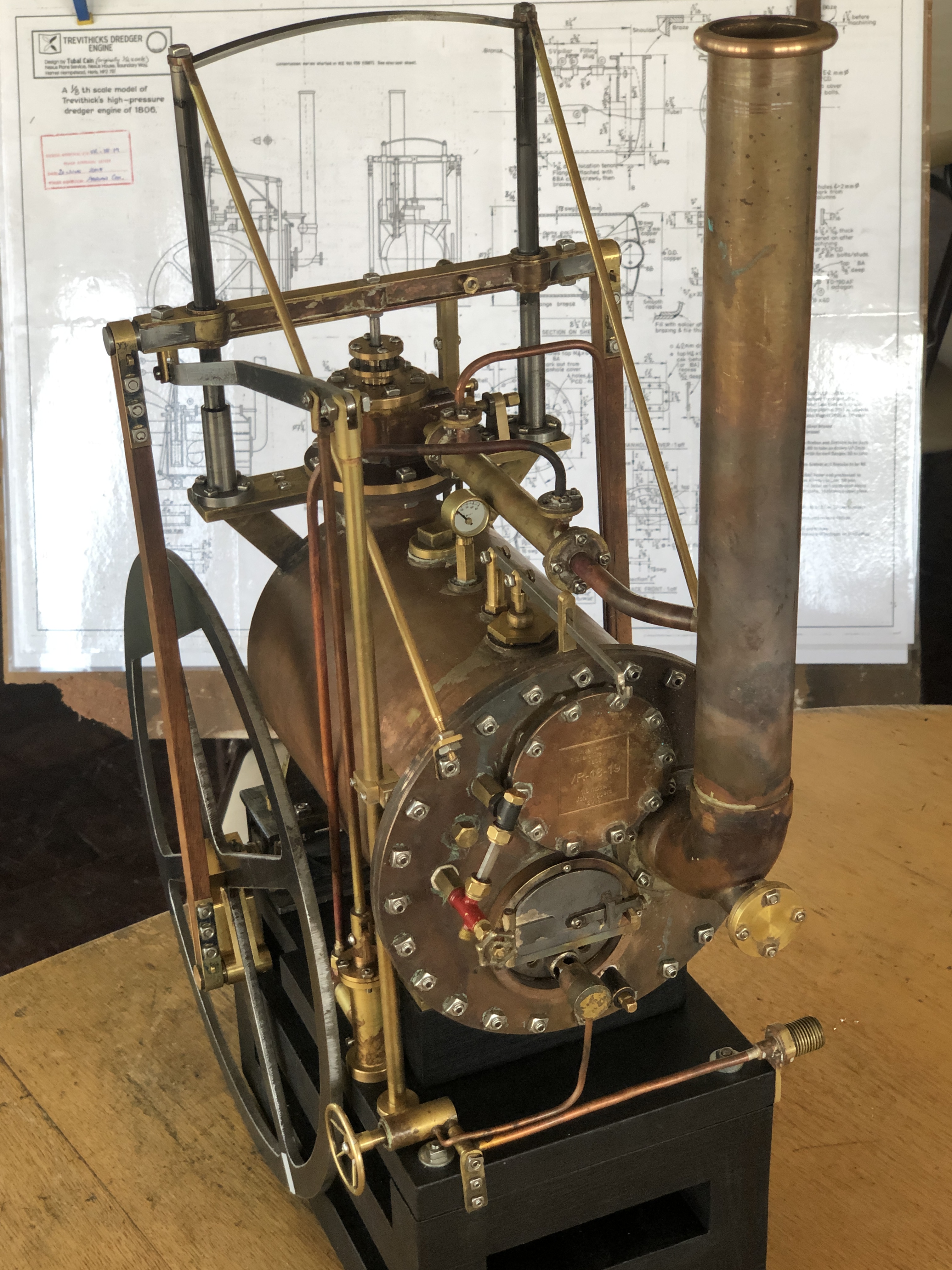
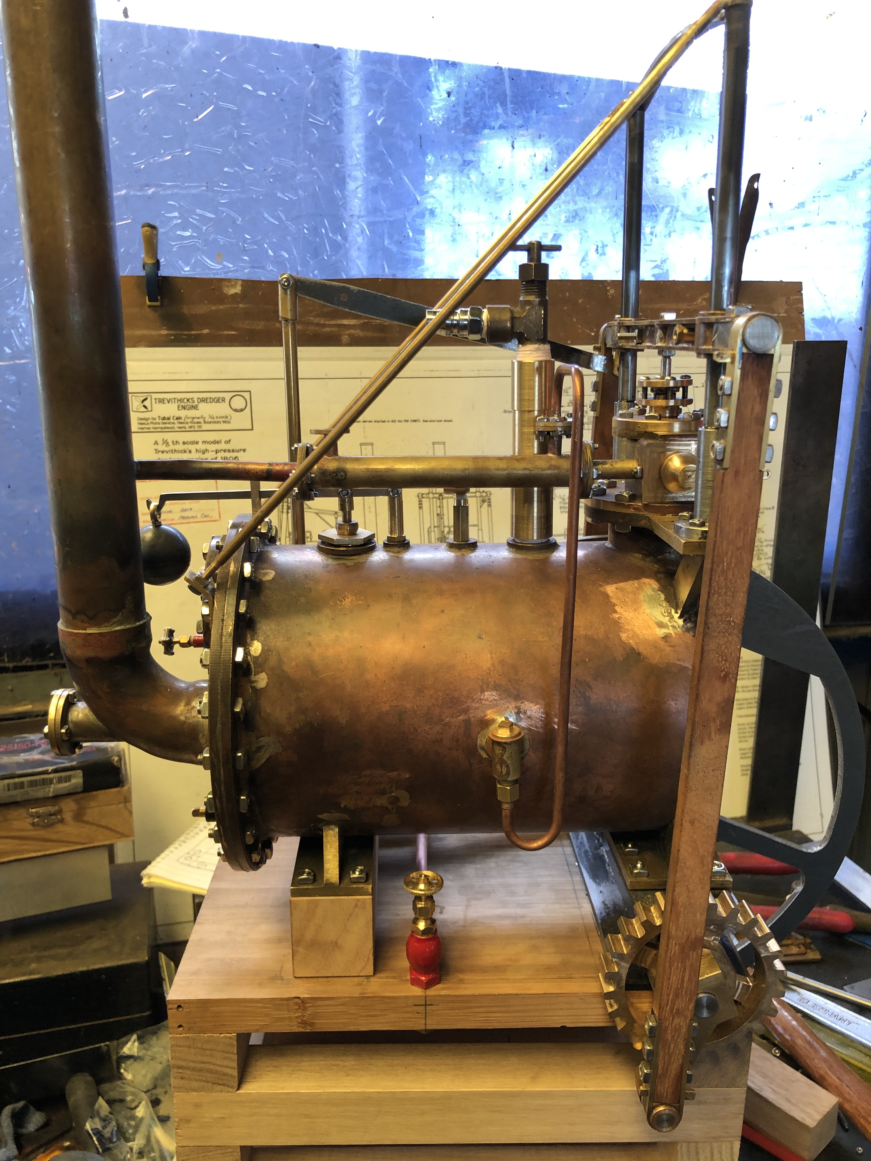
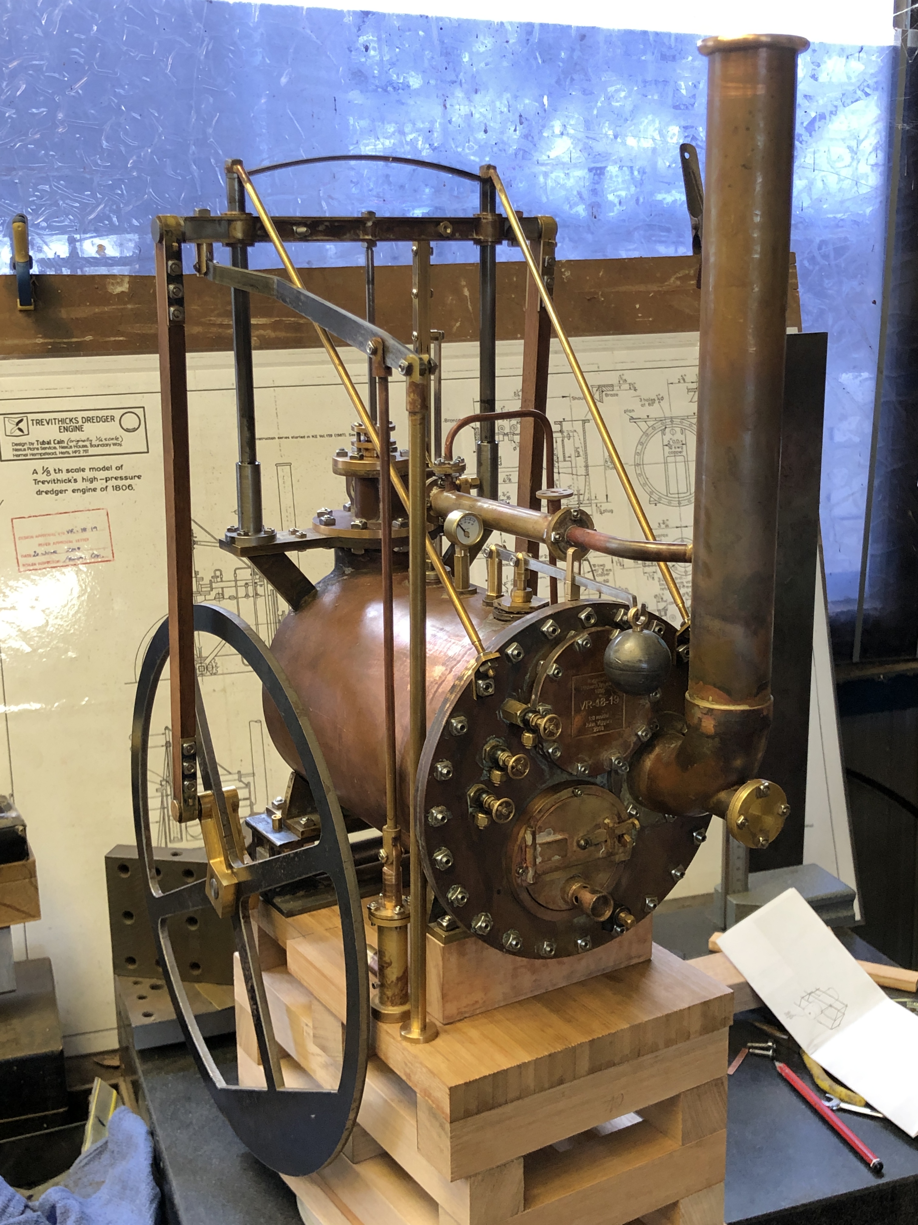
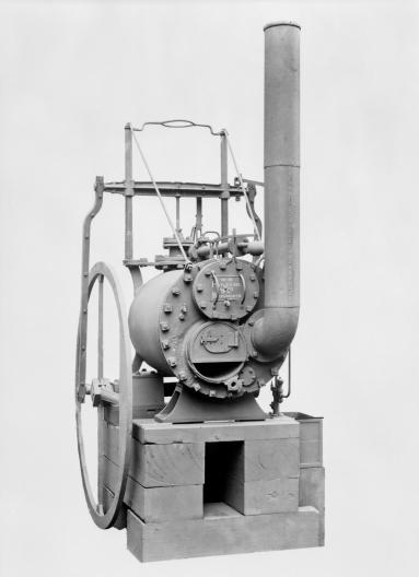
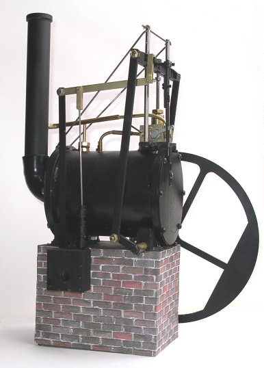
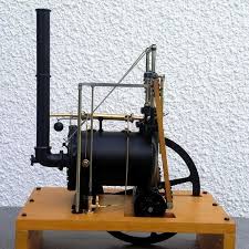
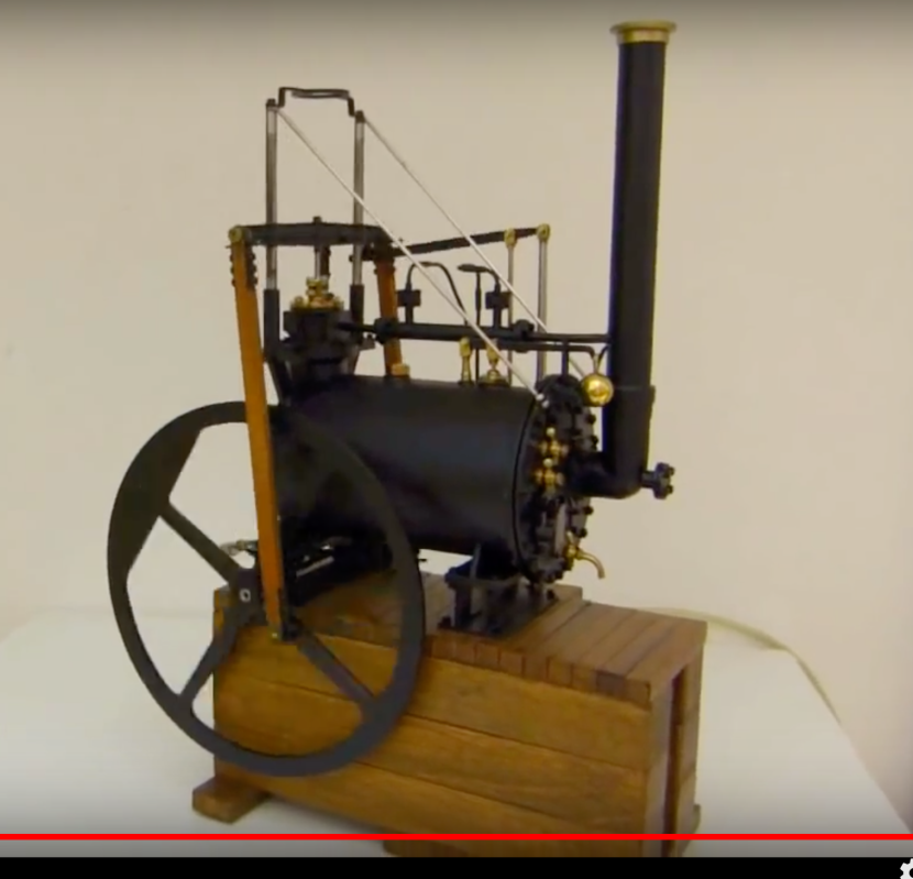
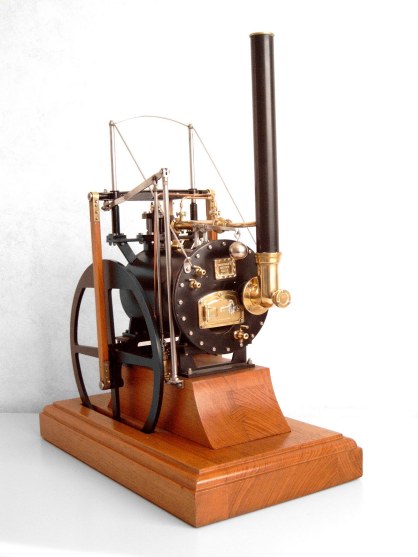
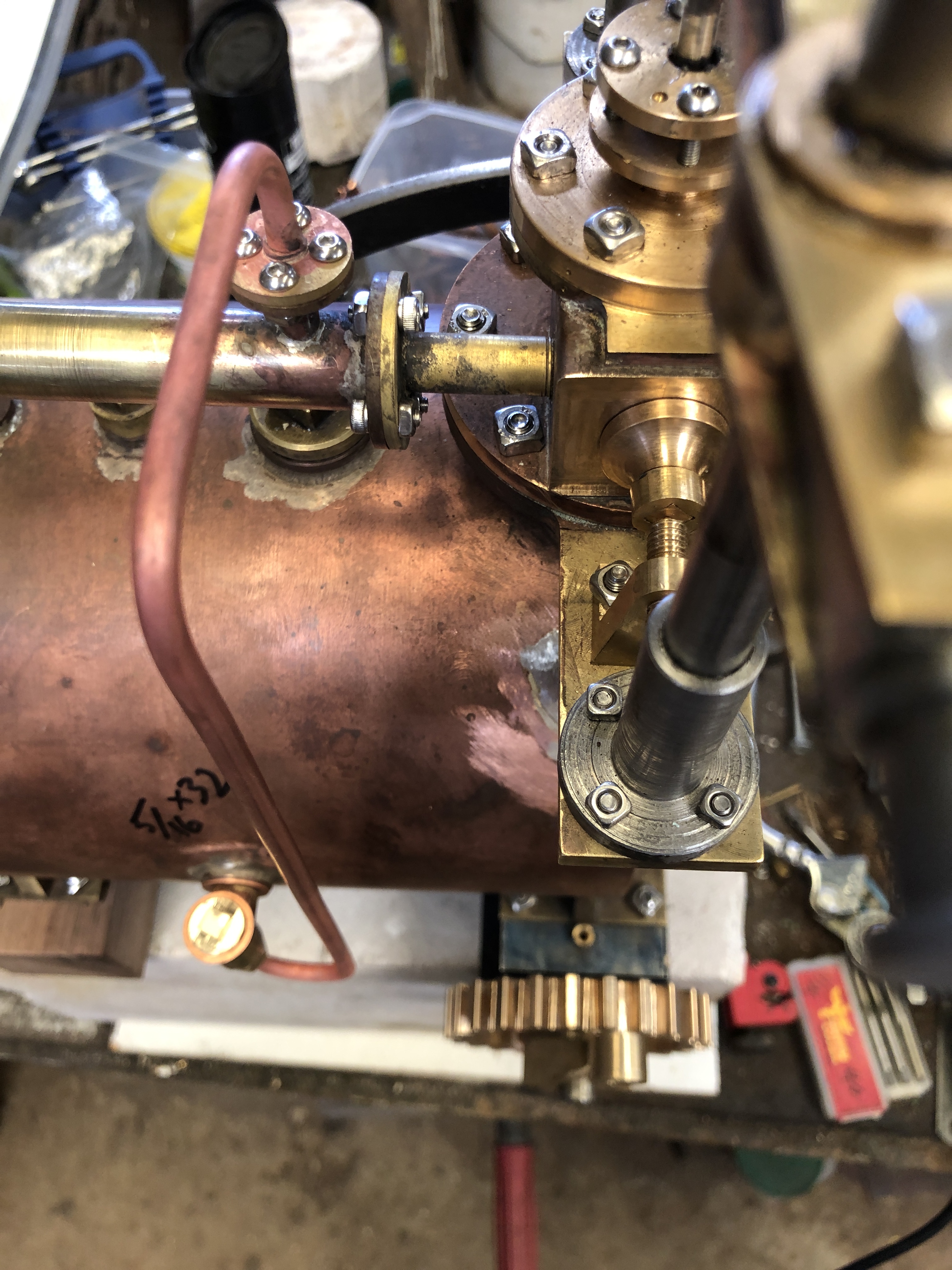
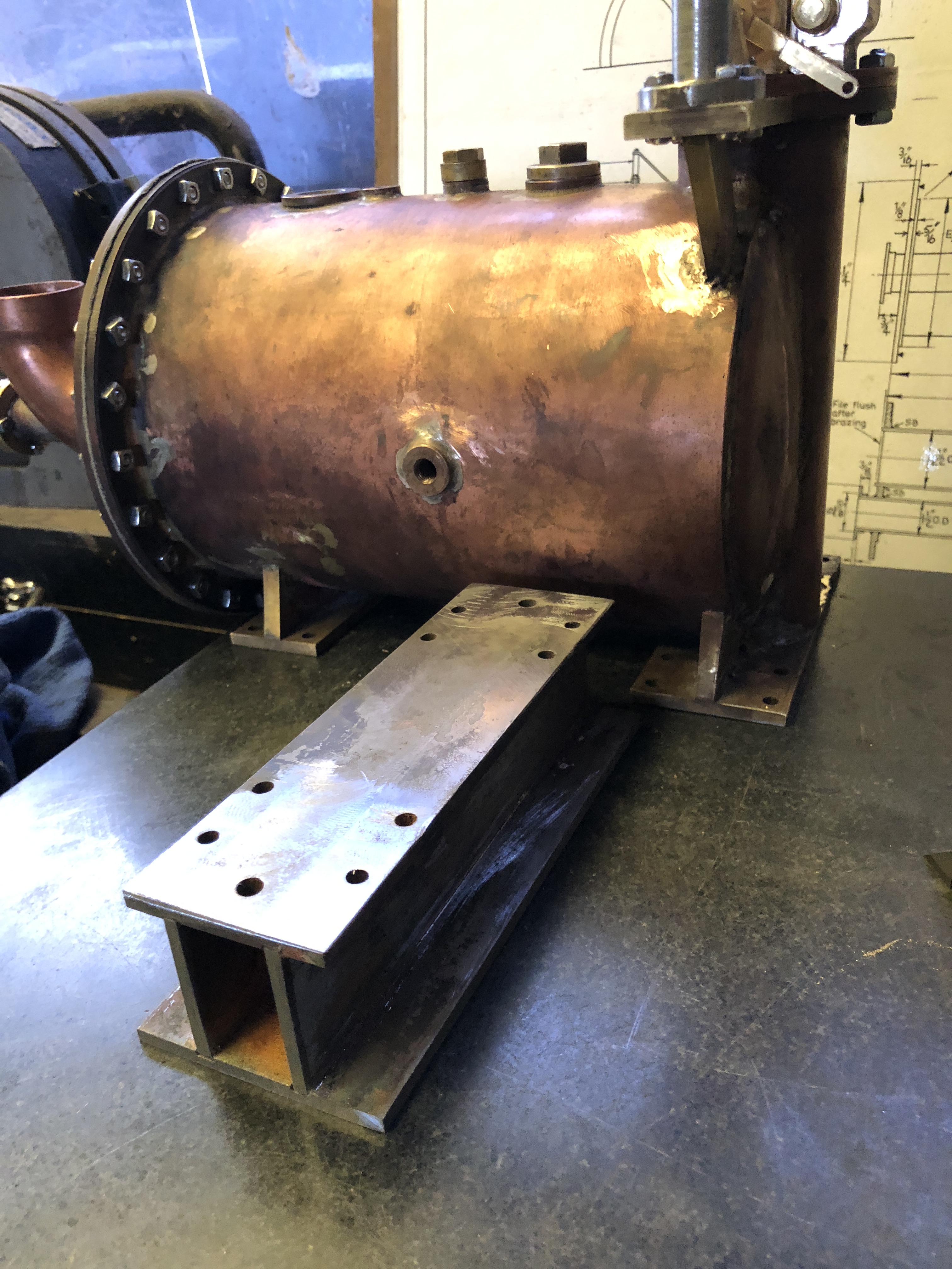
So, with a bit more practice I think that I might be able to bronze braze where necessary on the vertical boiler and the Trevithic dredger engine.

P.S.  Those readers who know about brazing will get a laugh.  I did the brazing without dark glasses!  None of the tutorials mentioned that dark glasses allow you to see what is happening in the molten puddle.  I found out about dark glasses at my model engineering club club meeting last night.  John.
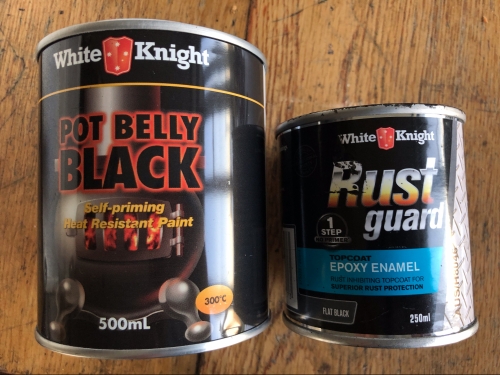
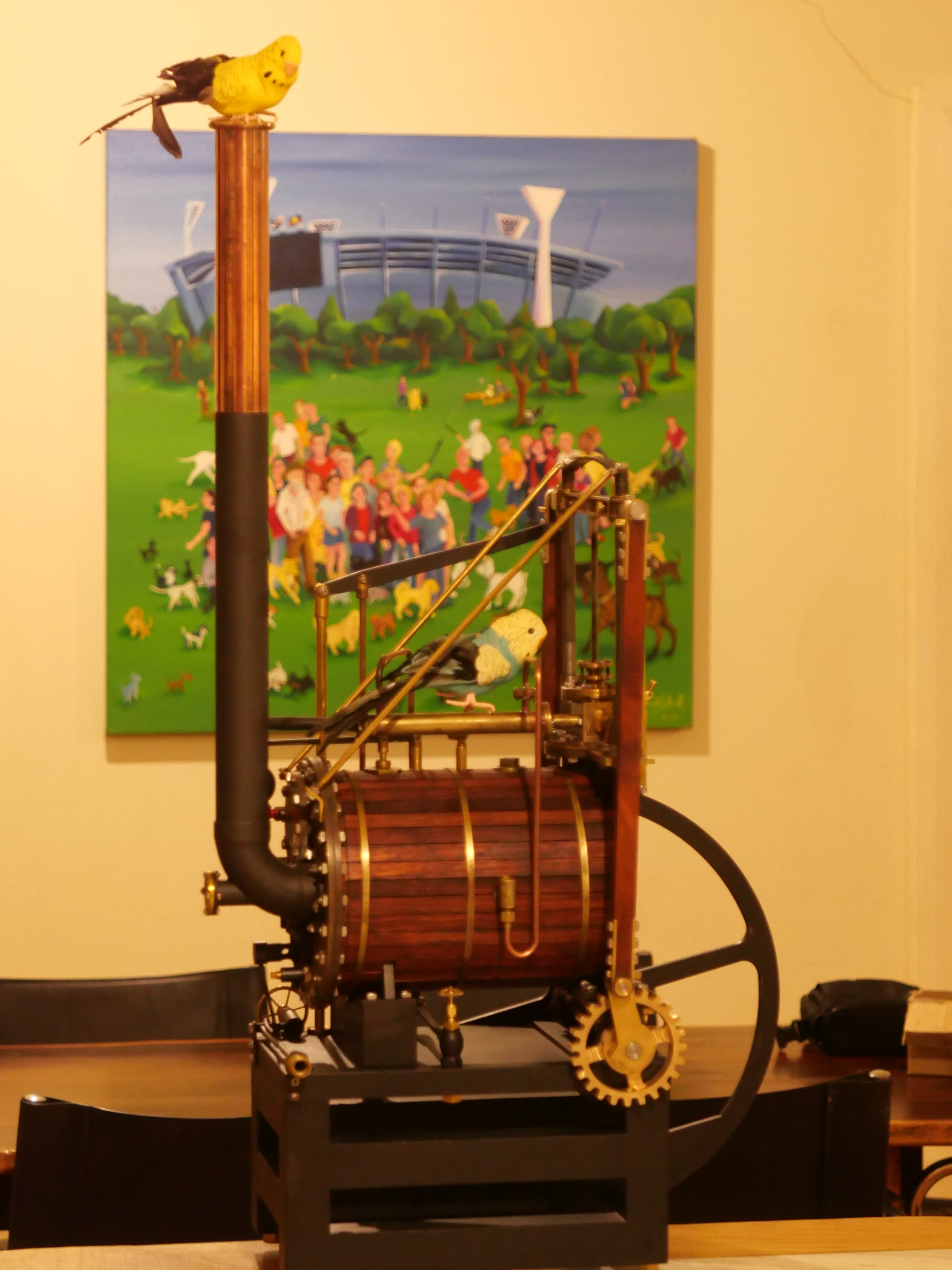
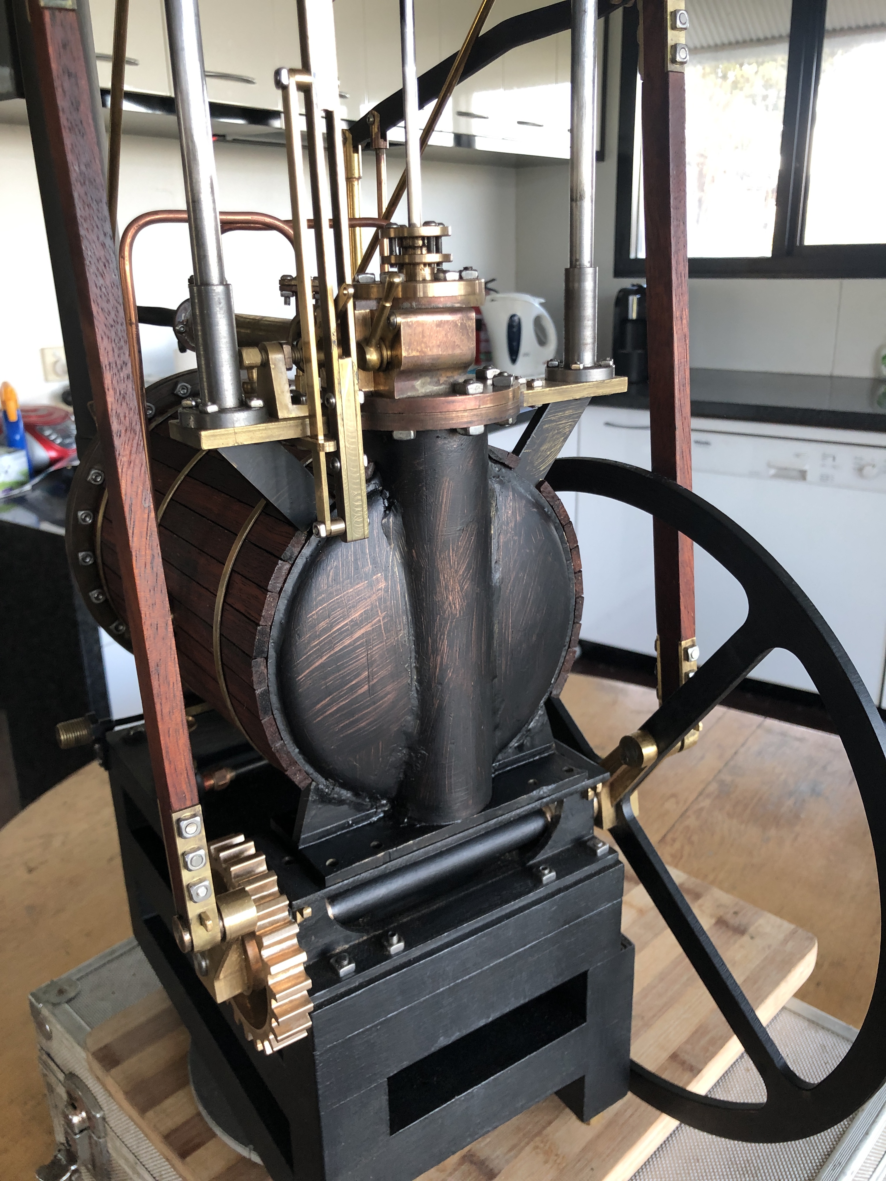
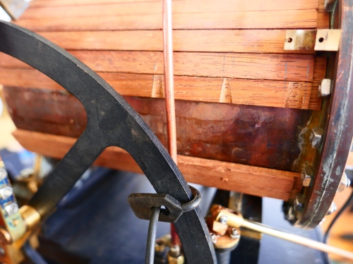
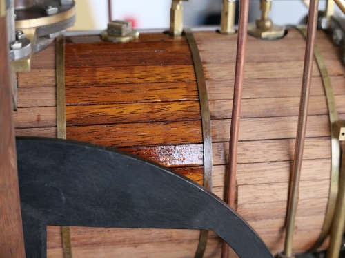
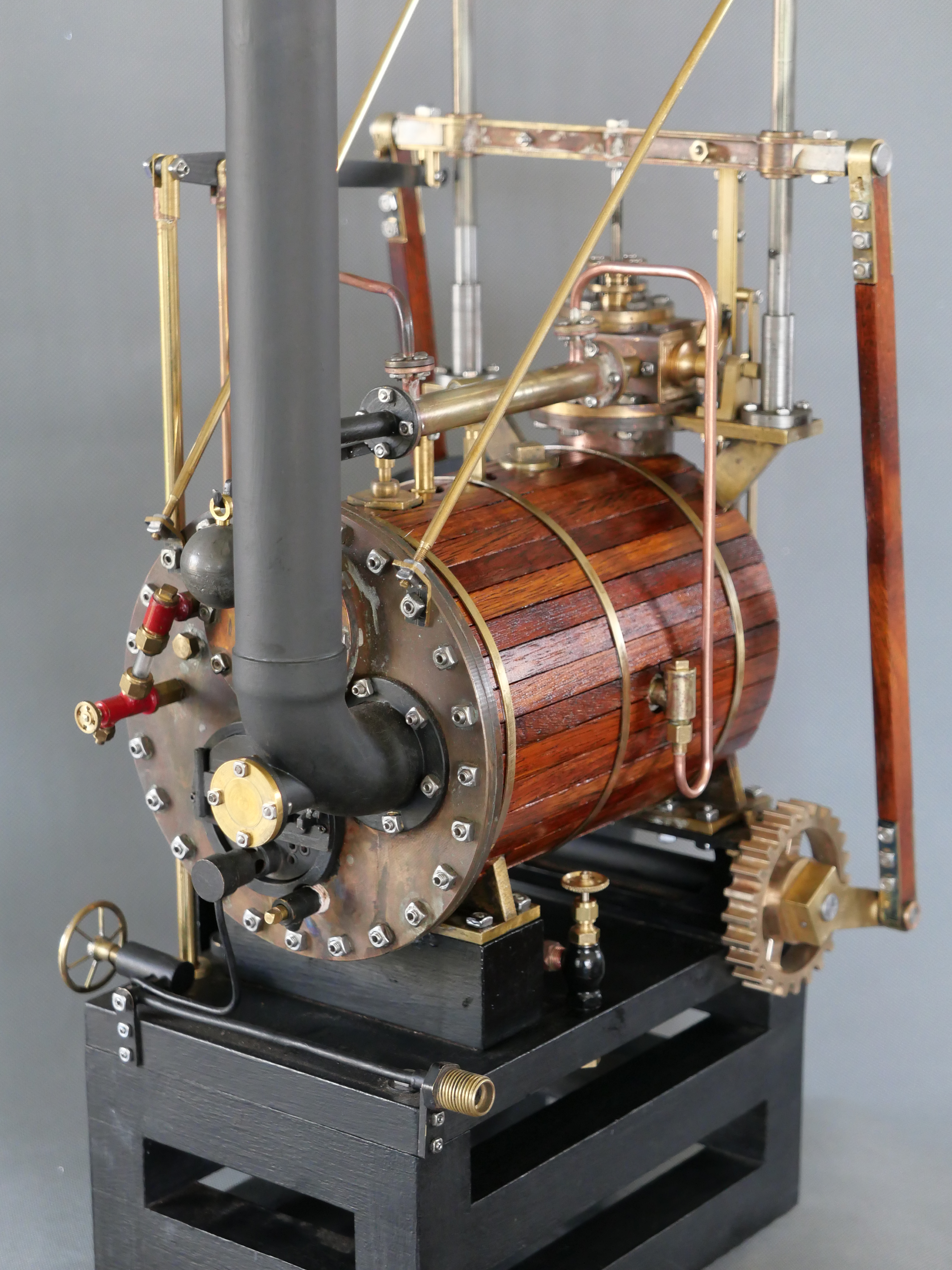
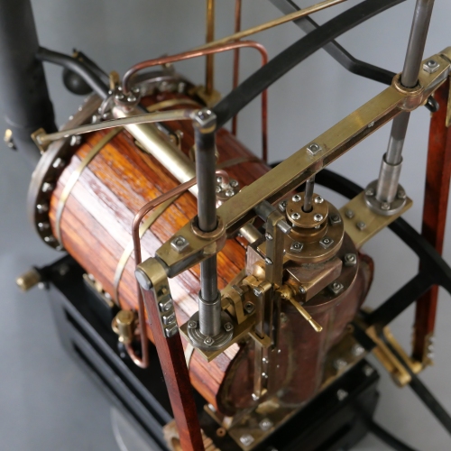
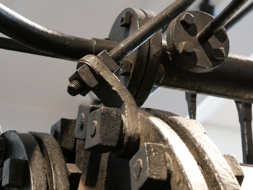
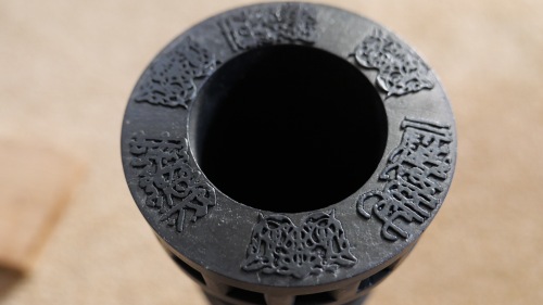
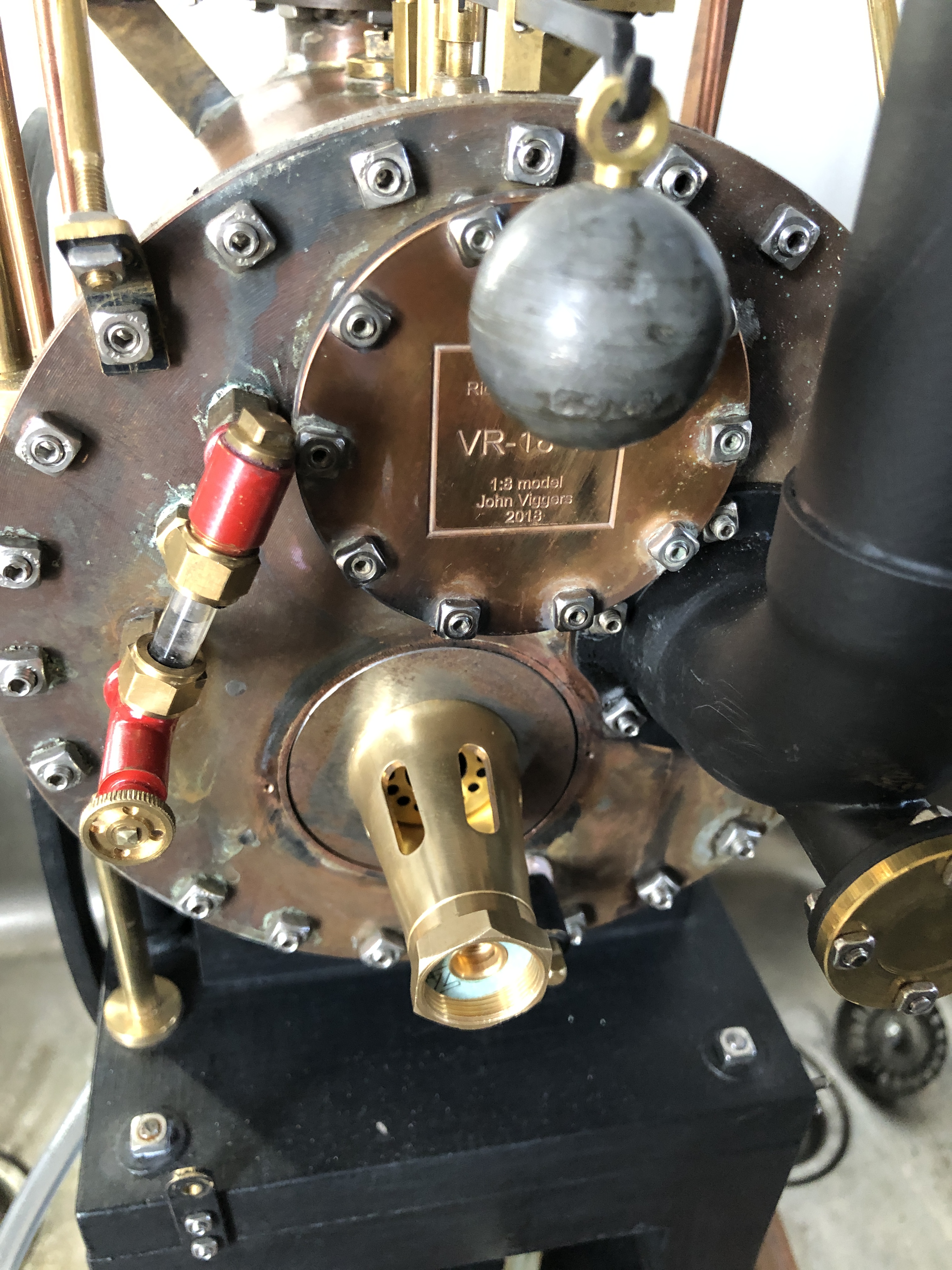
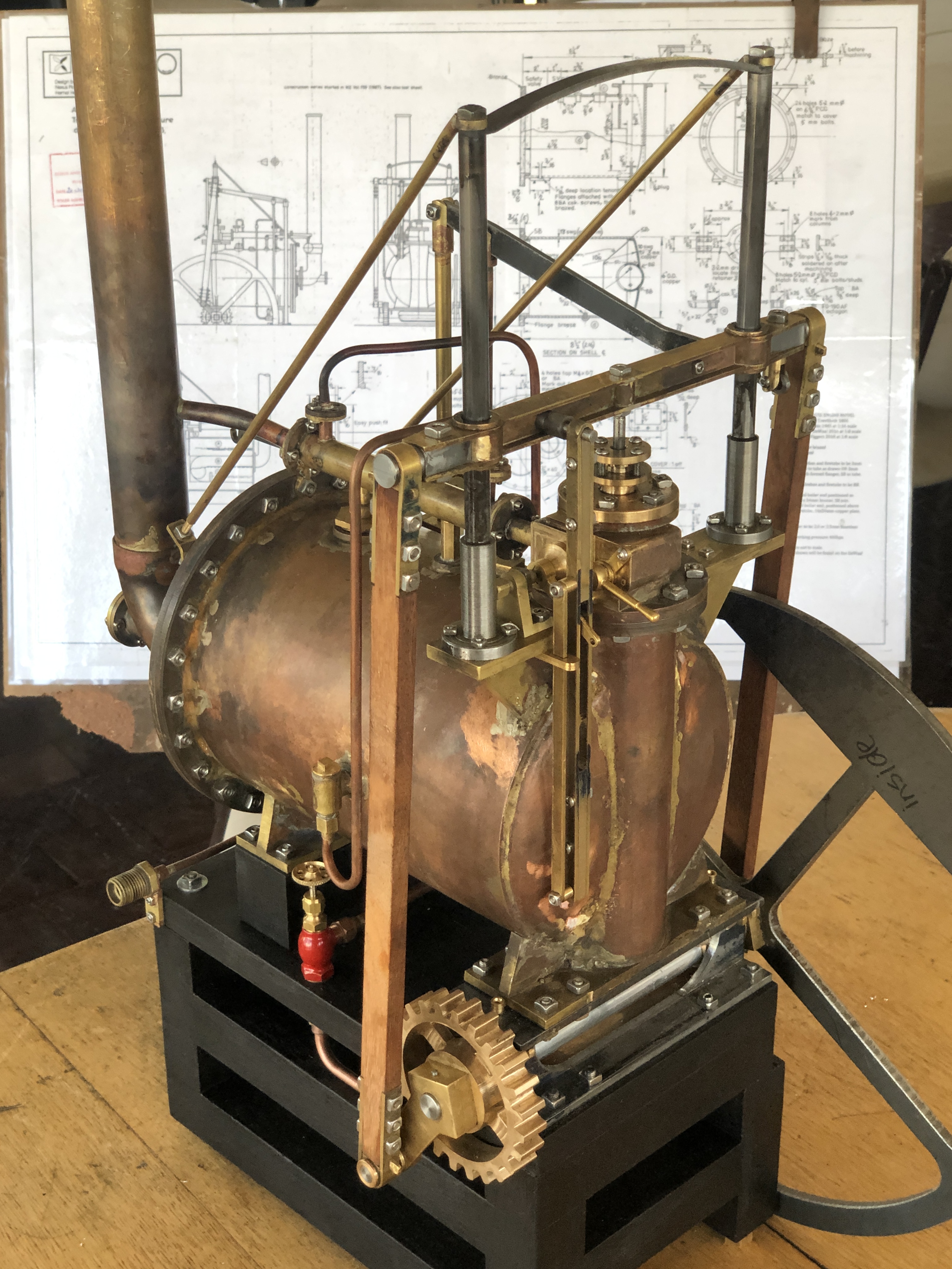
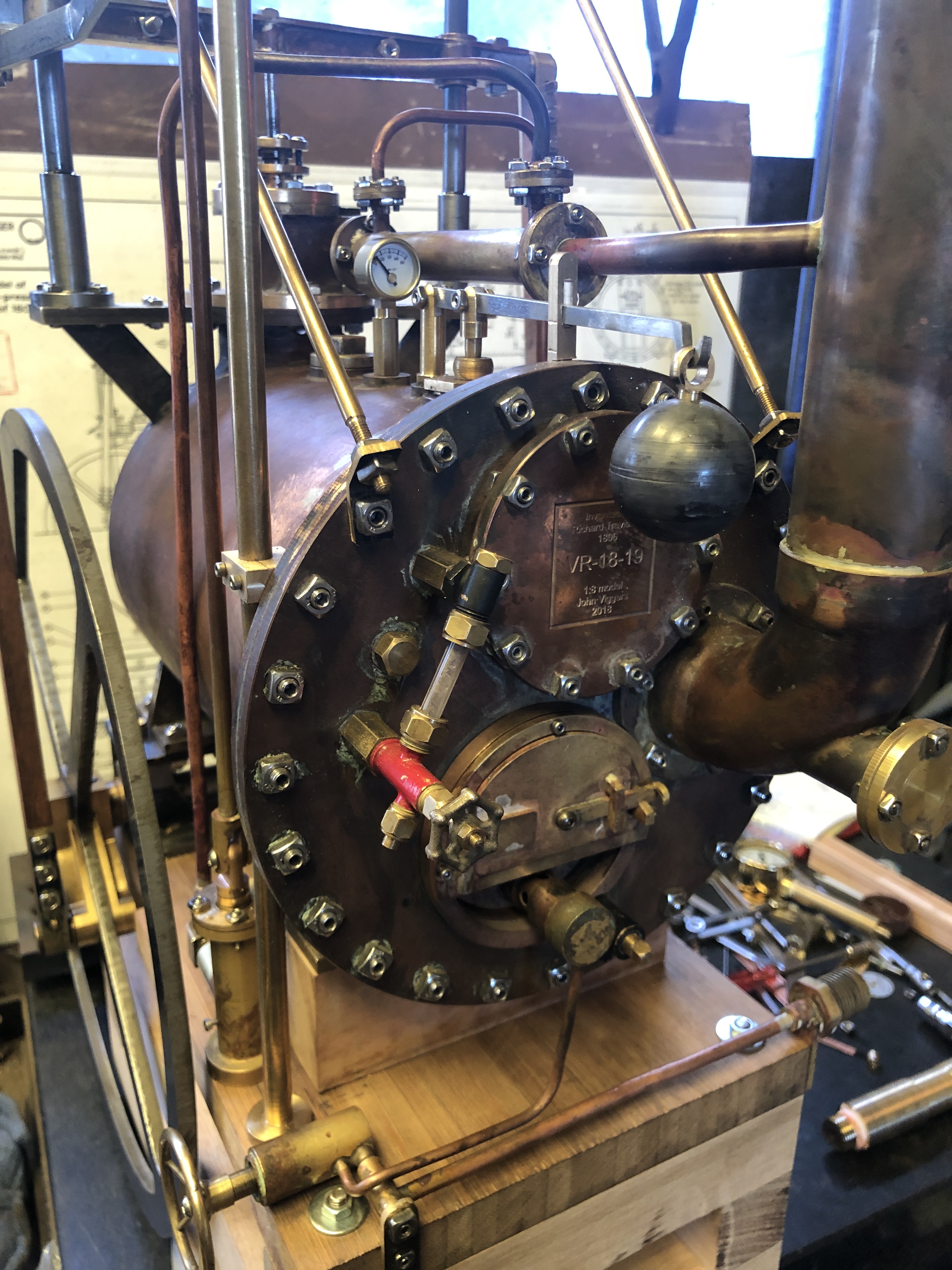
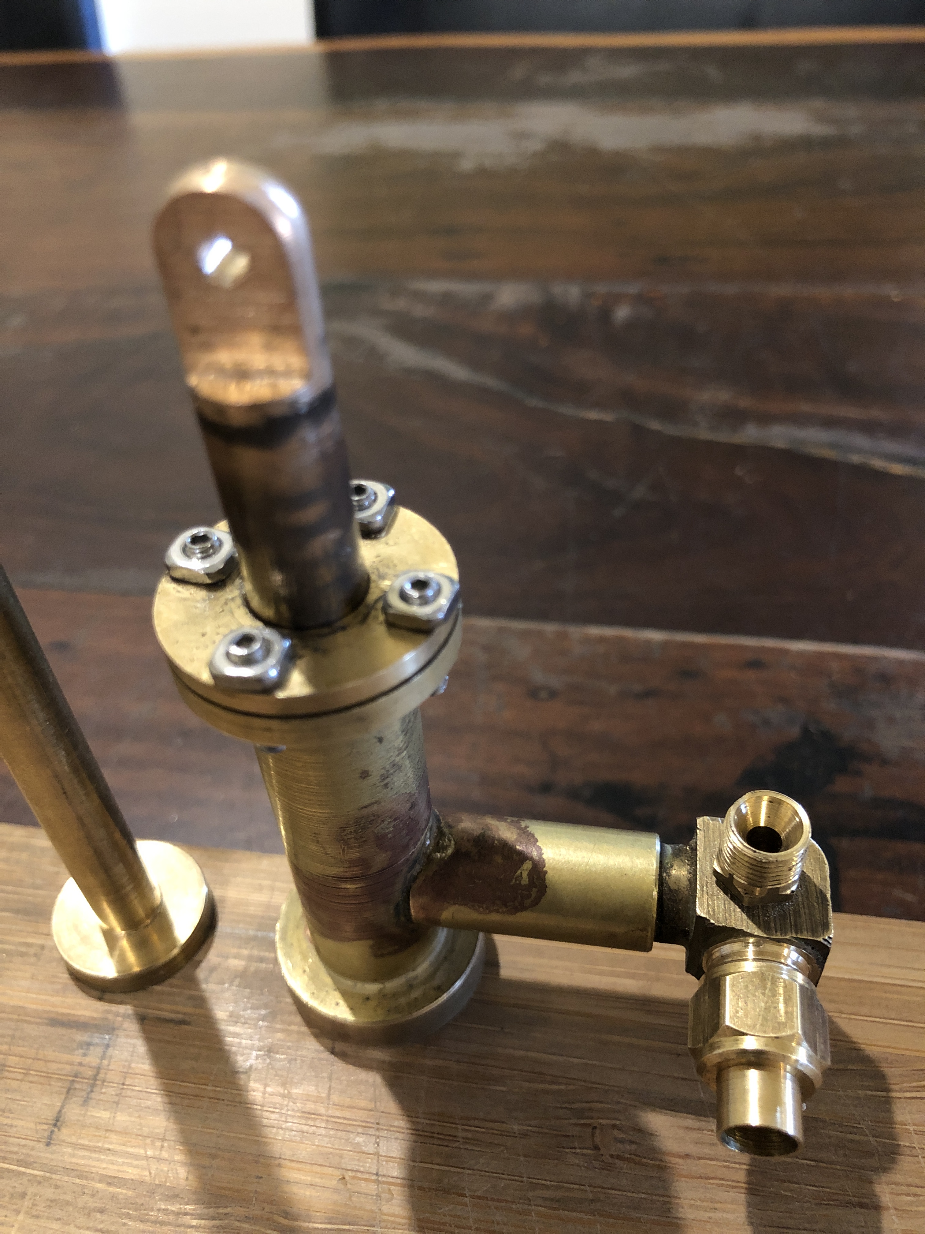
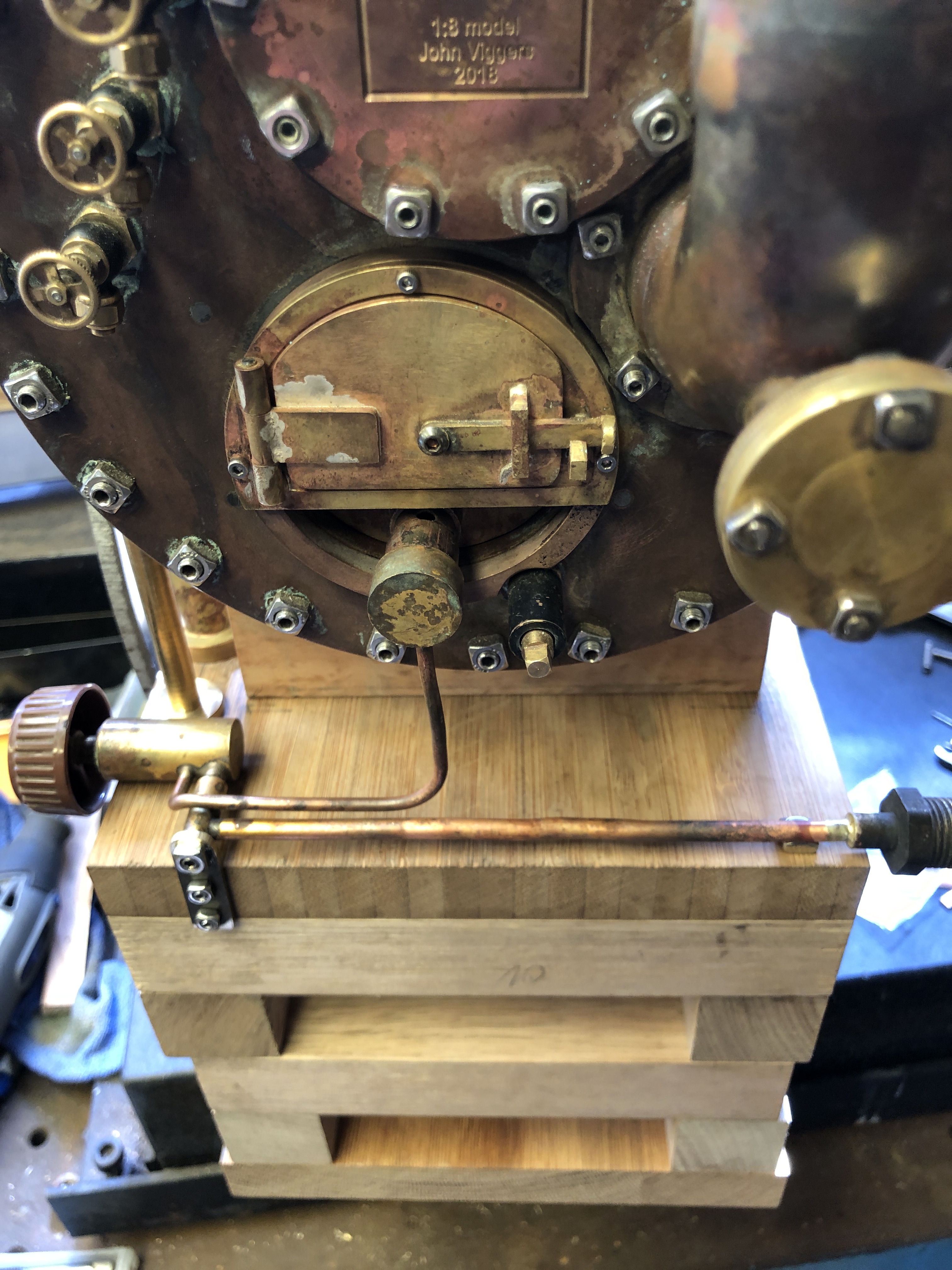
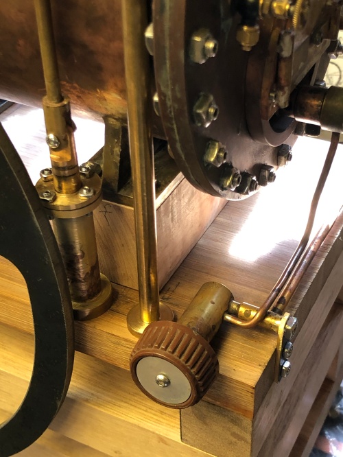
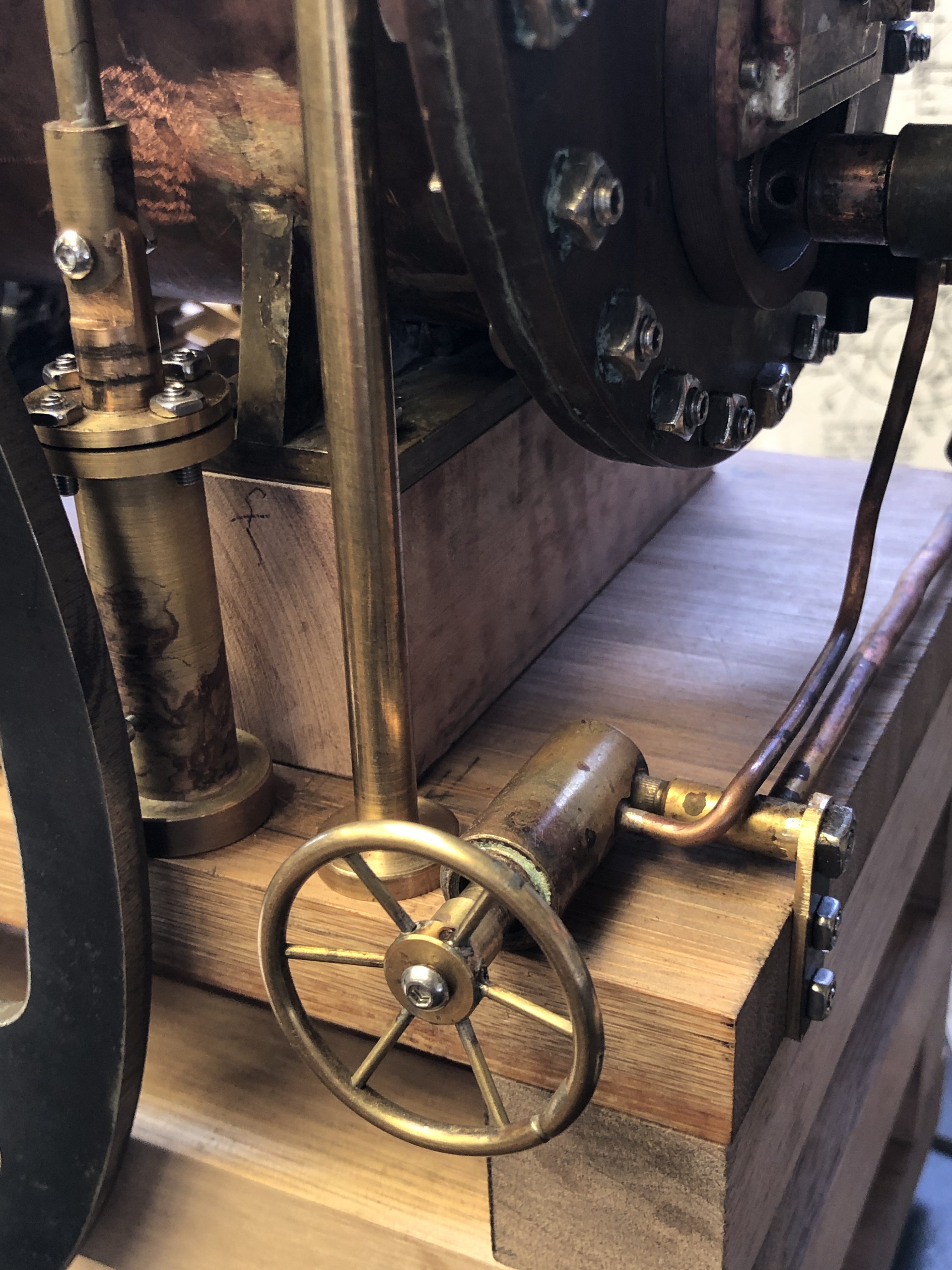
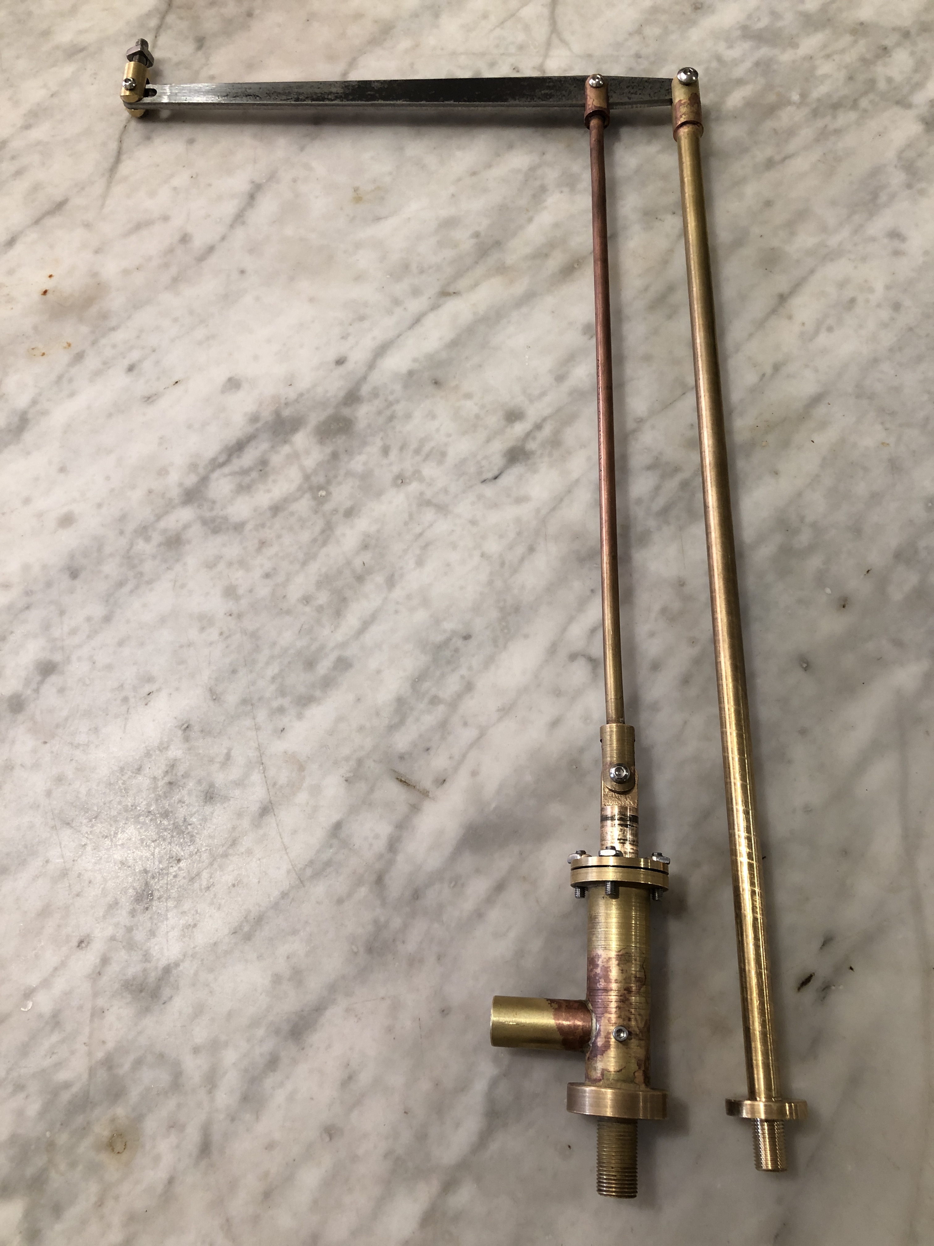
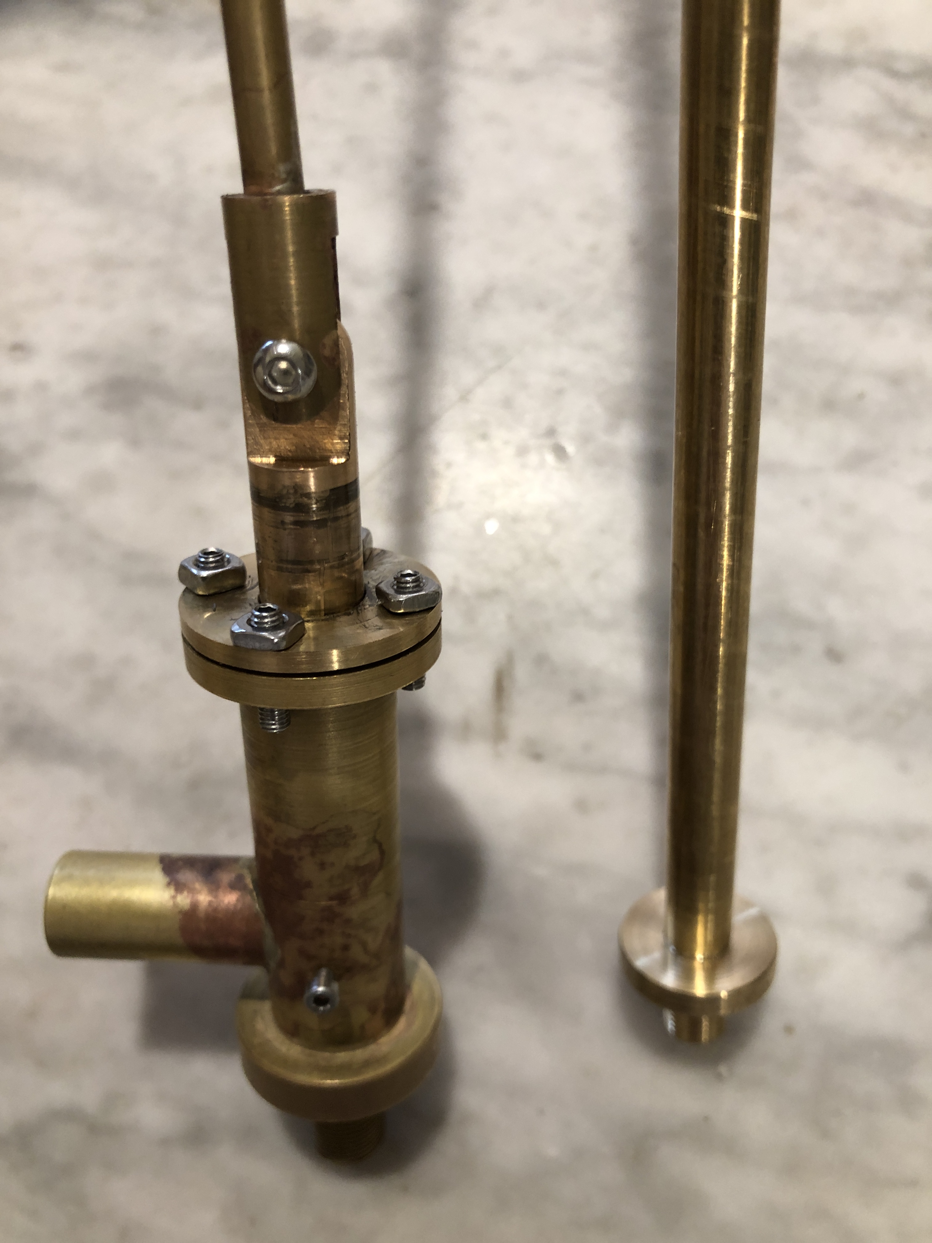
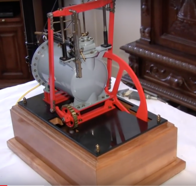
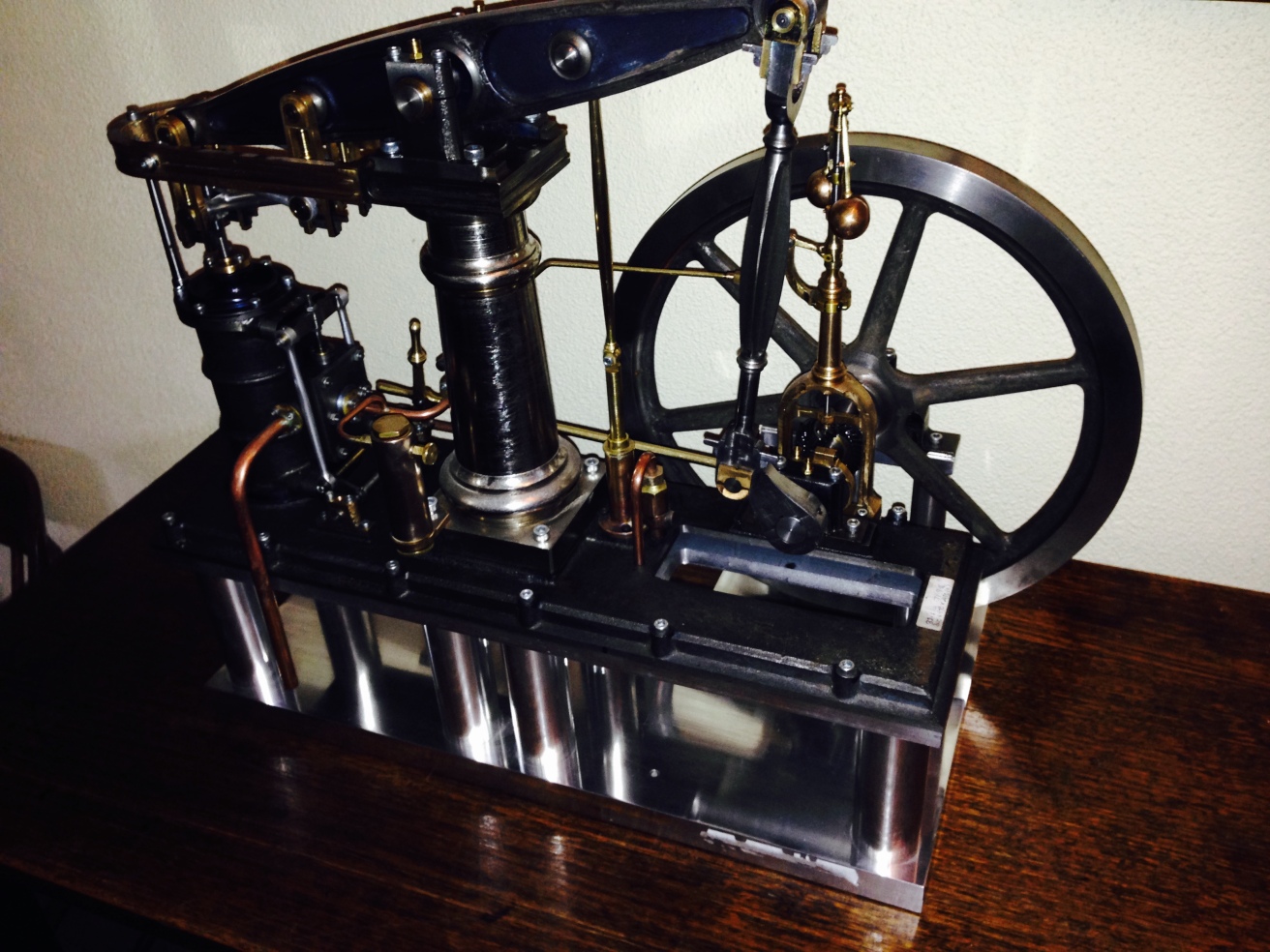
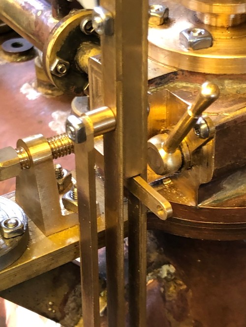
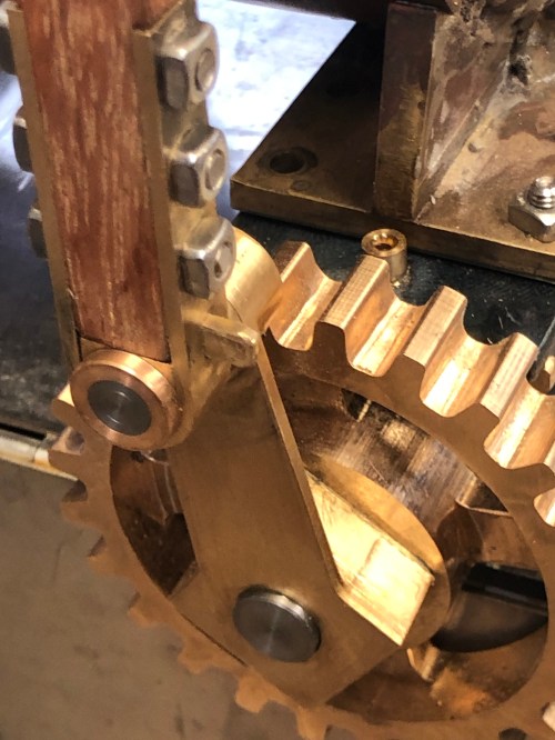
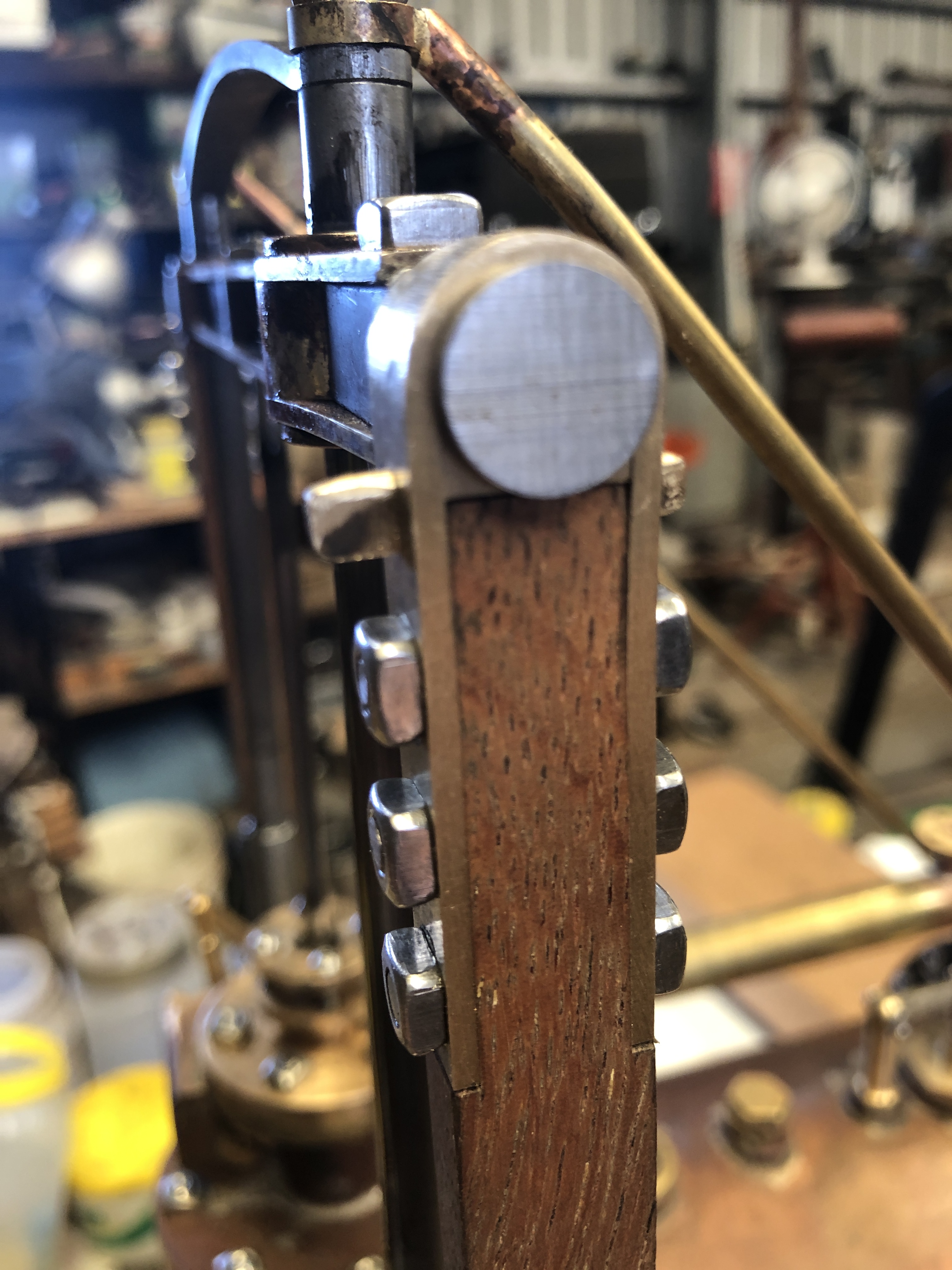
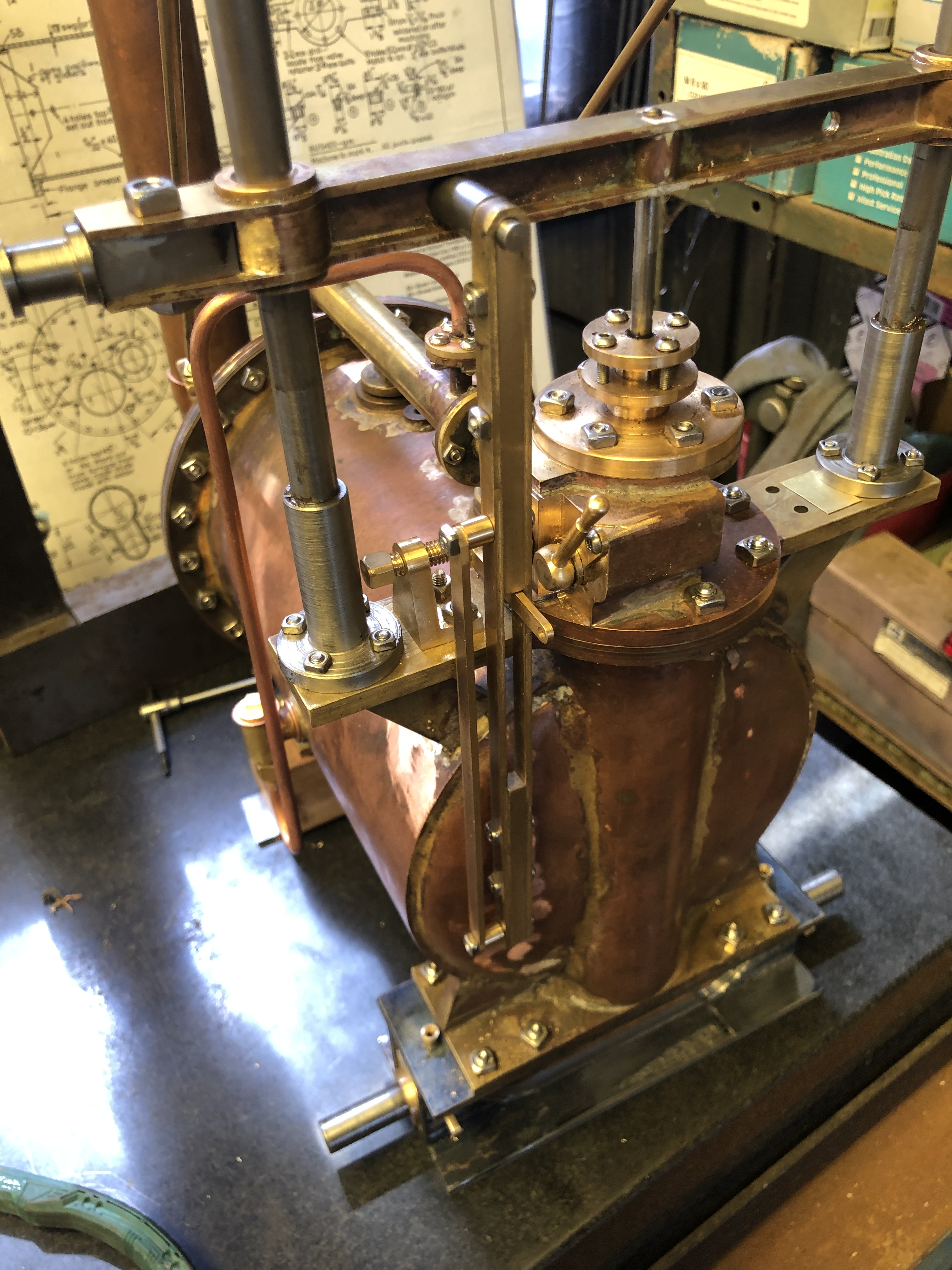
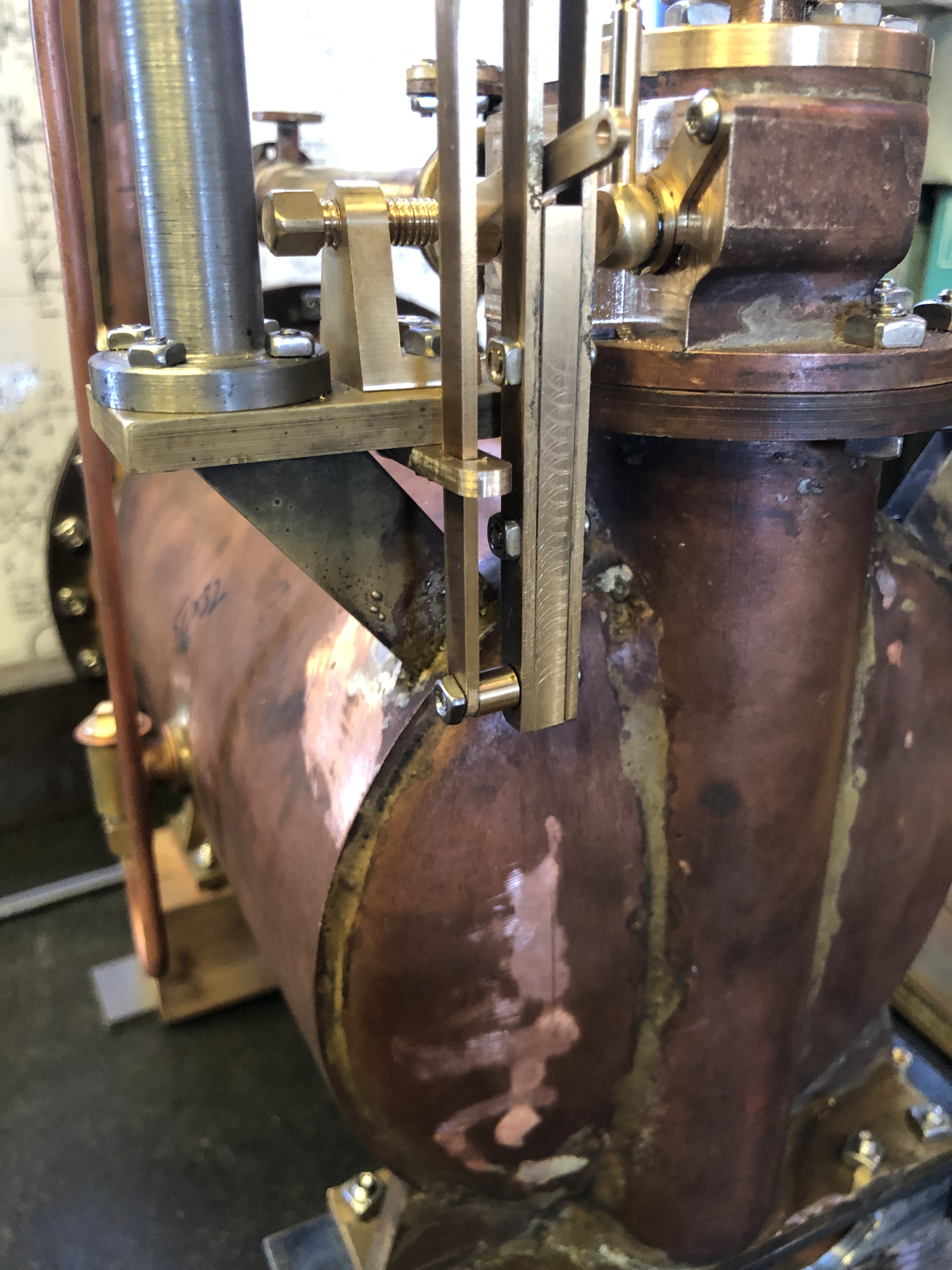
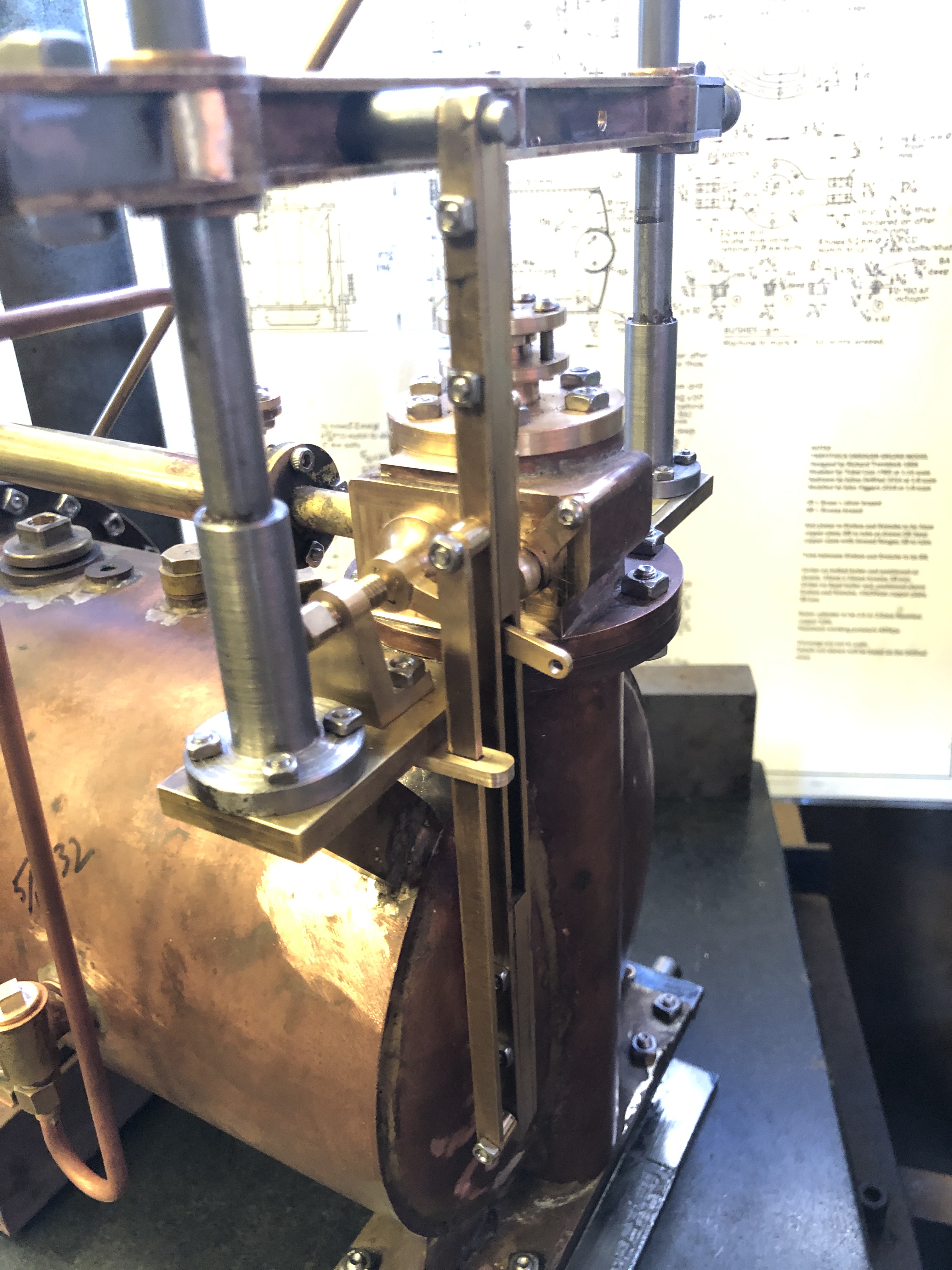
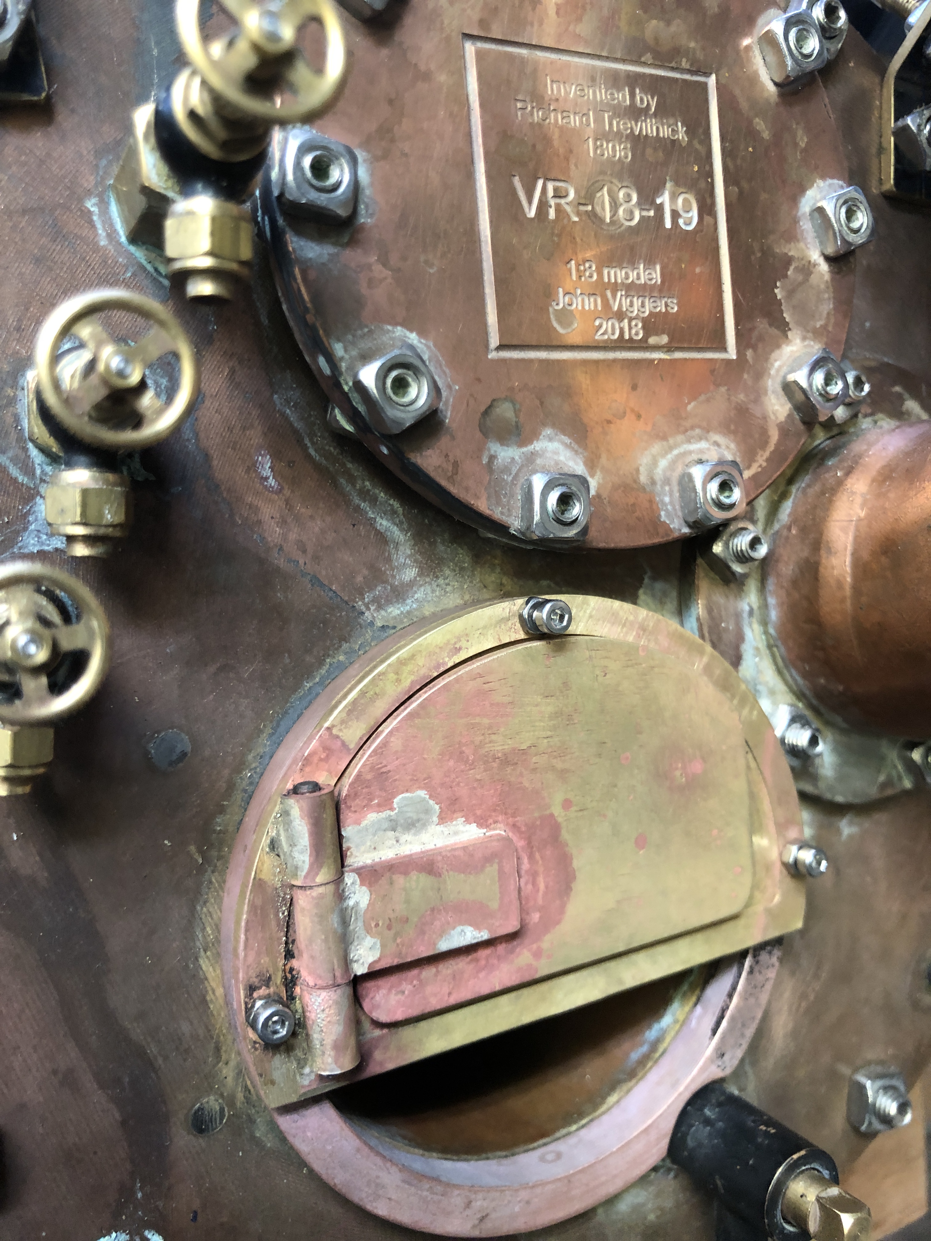
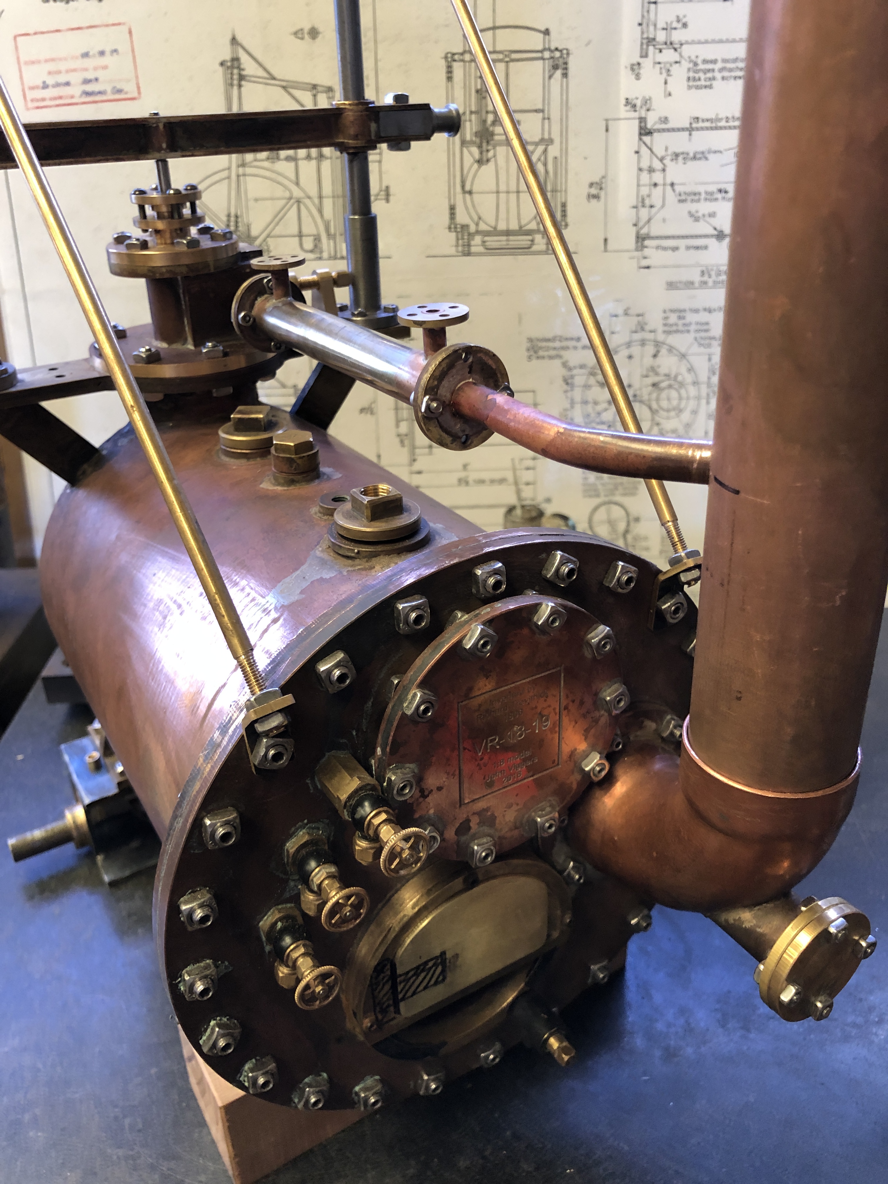
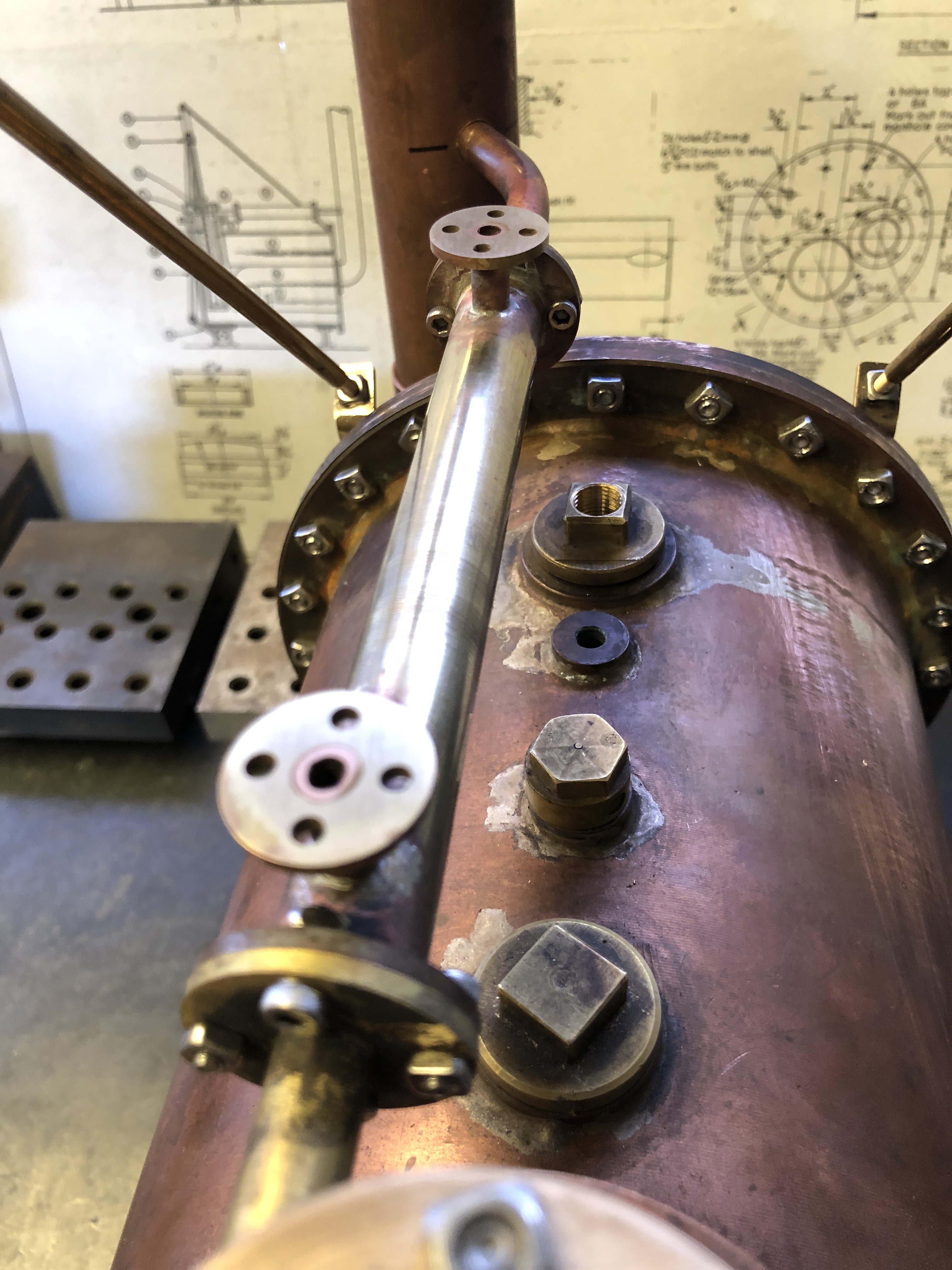
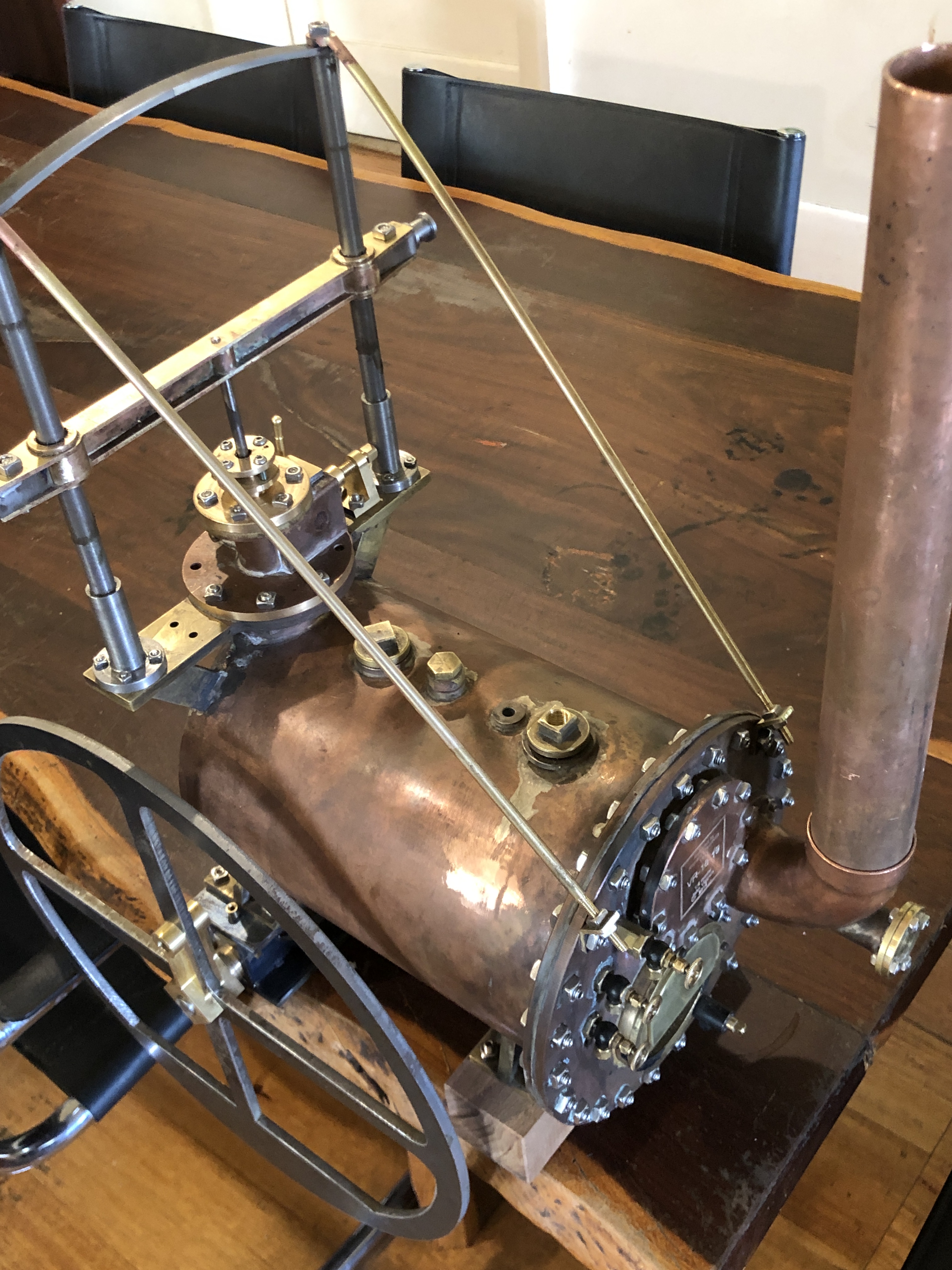
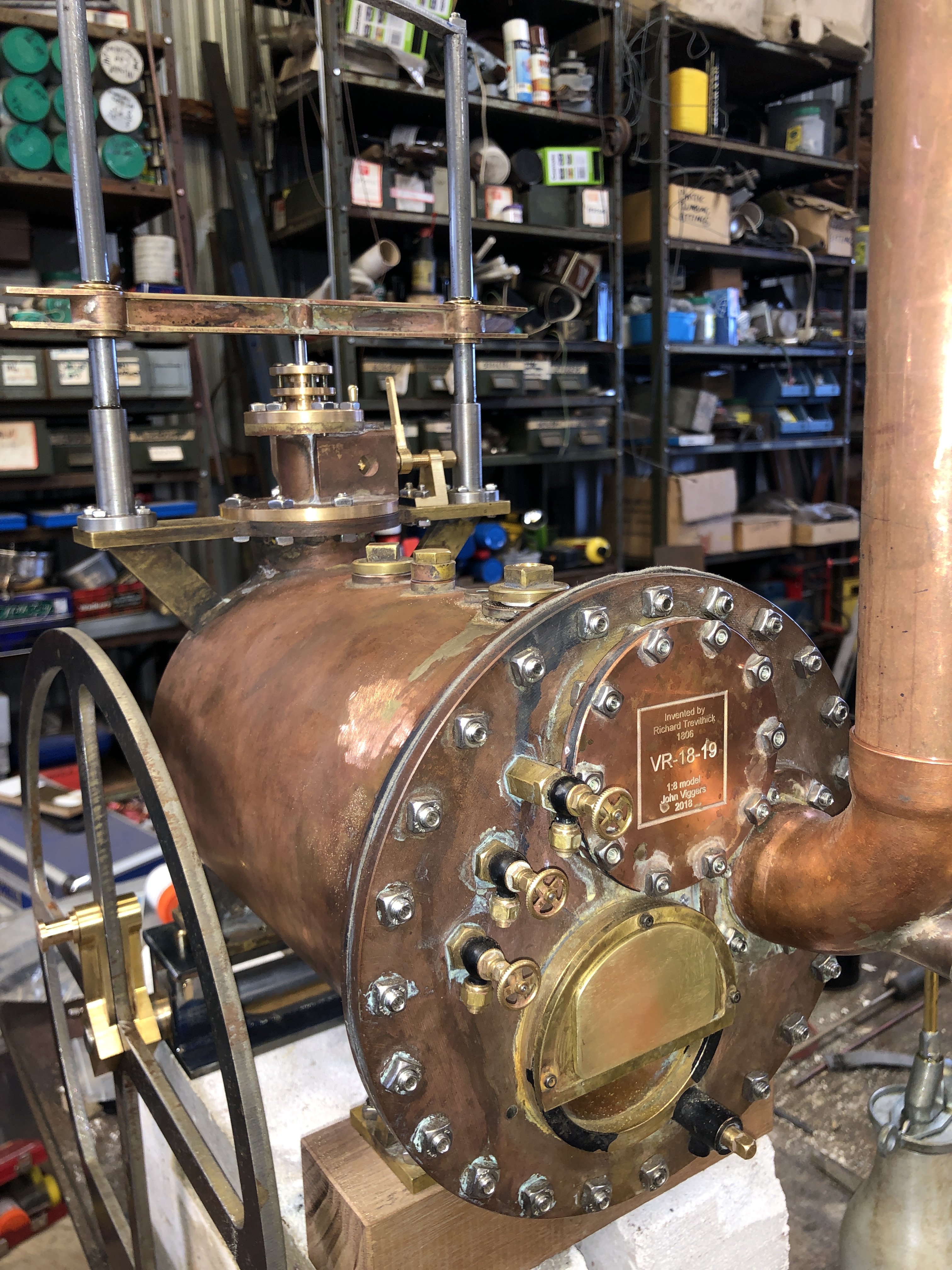
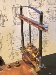
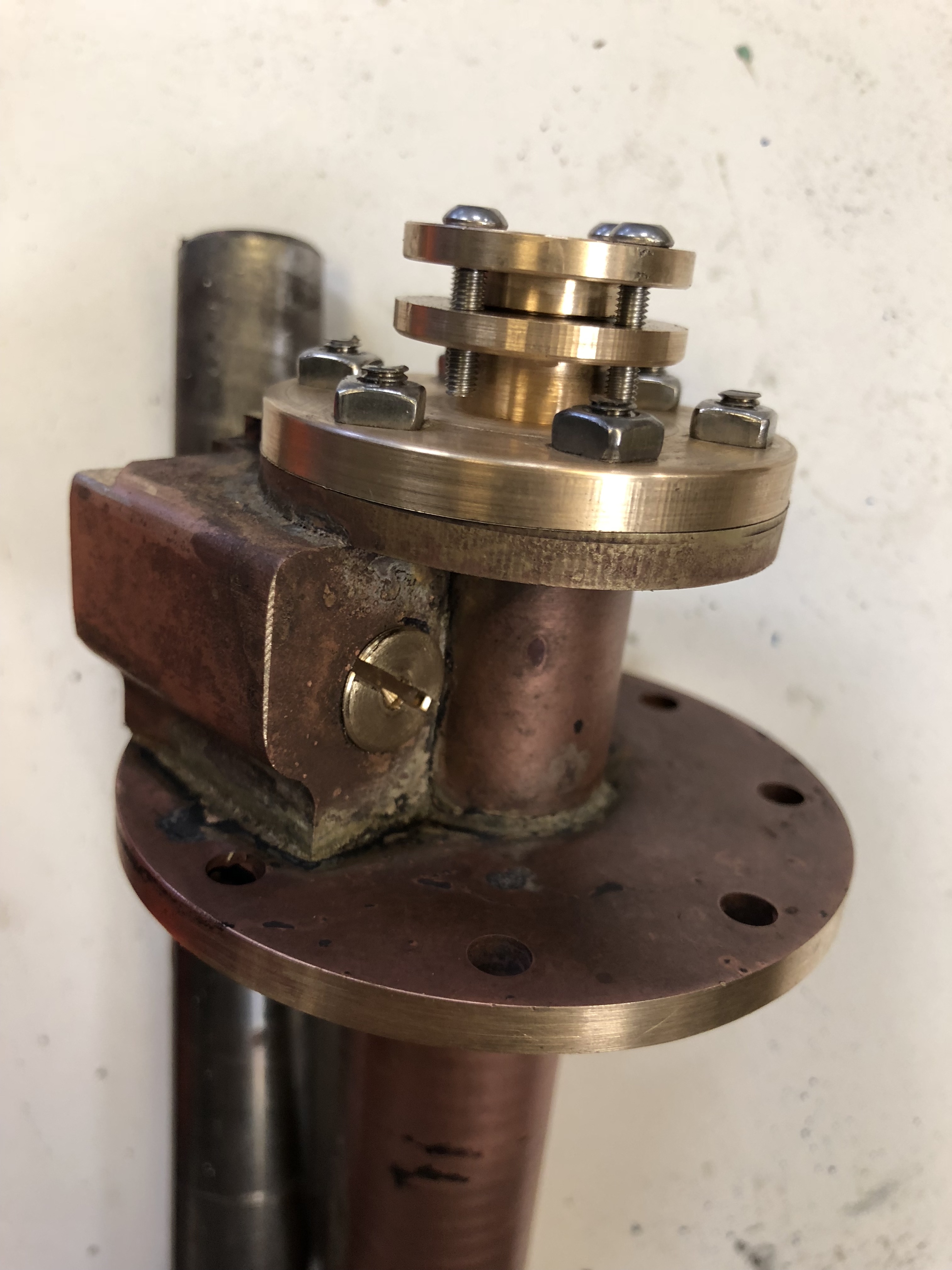
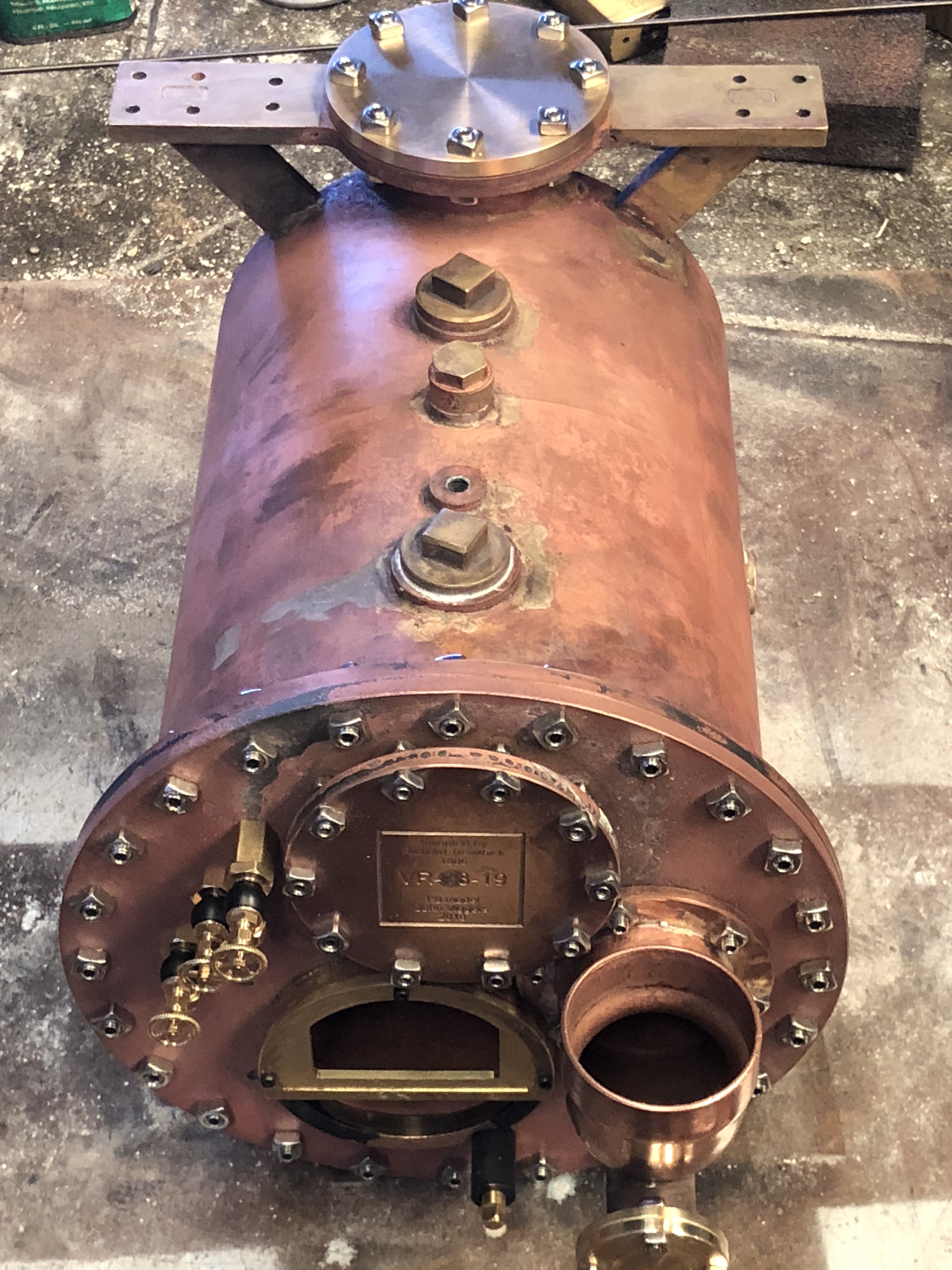
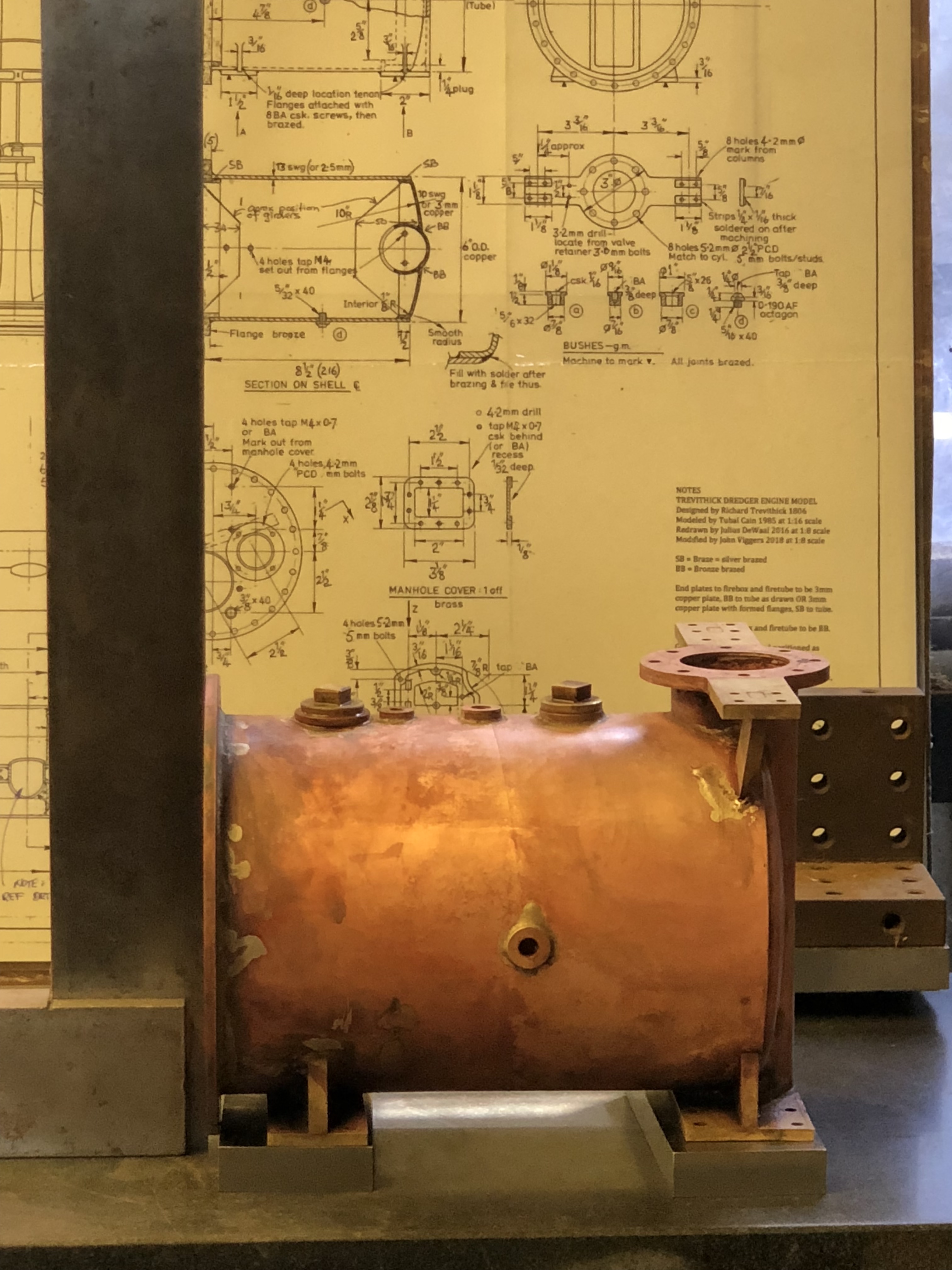
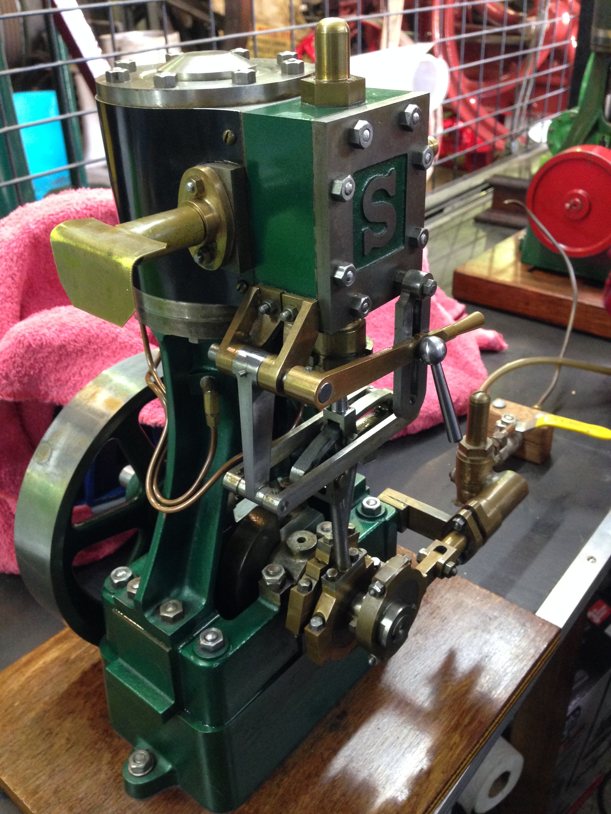
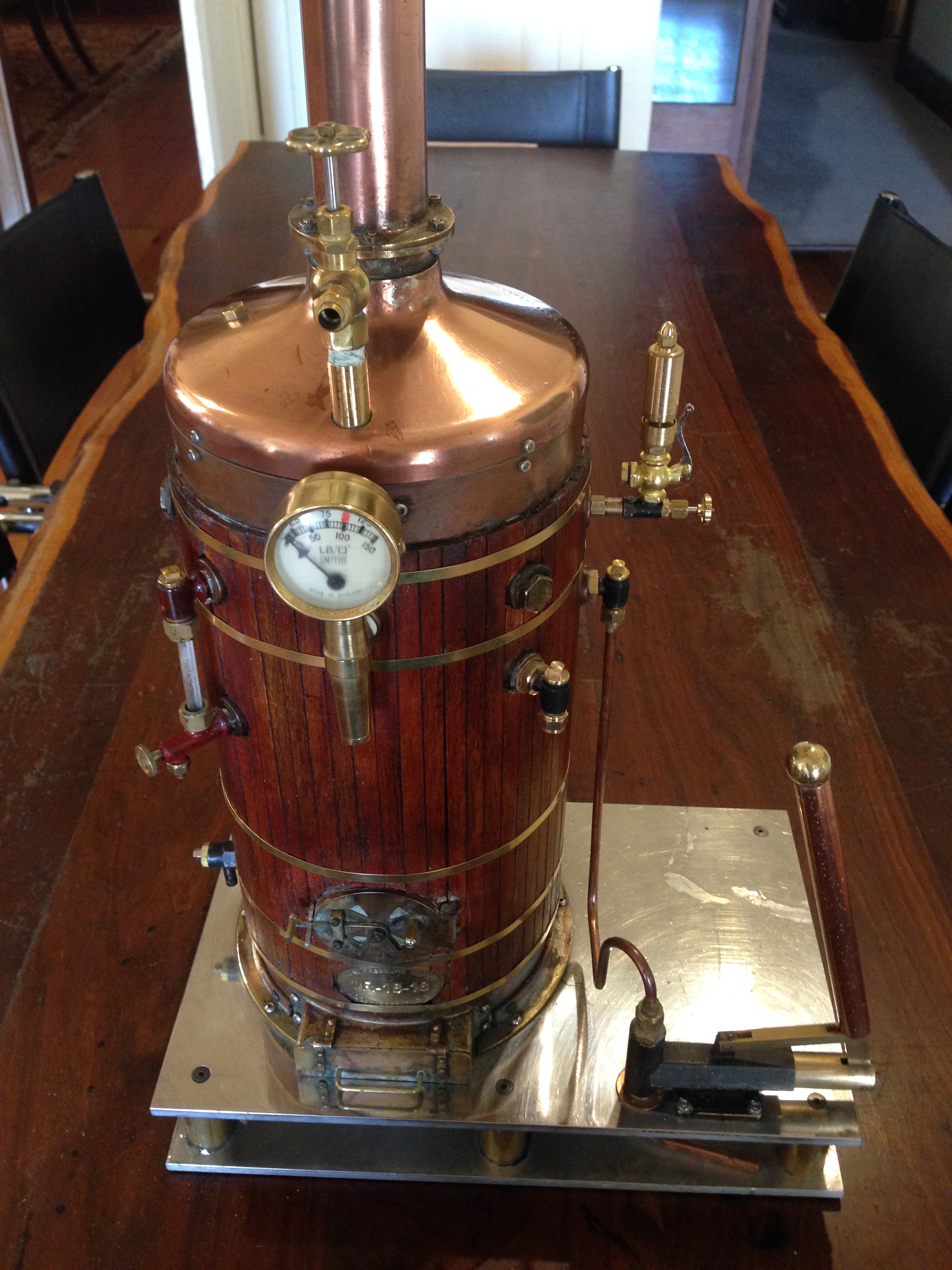
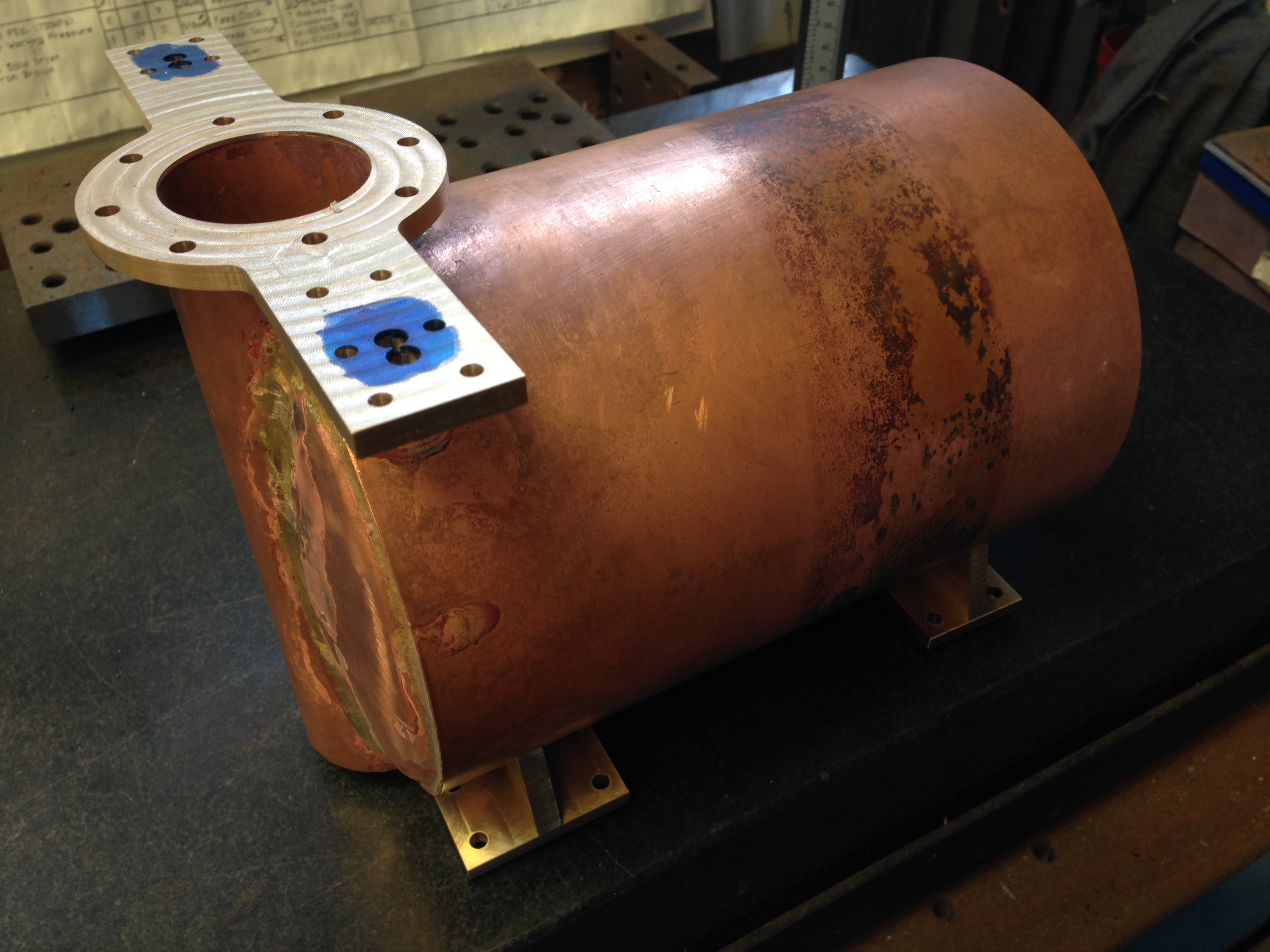


Another Use for Magnets

I purchased some bronze disks for use in the model Trevithick dredger engine.  The disks 204mm diameter had been bandsawn off rod.  I had specified minimum thicknesses of 7mm and 12mm.  One disk was 9.2-9.7mm thick and the other was 12-15mm thick.

bronze blanks.JPG

The bandsawn blanks of LG2 bronze.

In preparing the disks for machining I filed off a few protrusions, and using a straight edge, identified the valleys and ridges.

The thicker disk was held in the 3 jaw chuck and both faces were turned flat with no problems except avoiding the needles which were thrown off in a wide arc around my lathe.  Final thickness 12.5mm.  A persisting divot should be able to be avoided in the final part.

The thinner disk needed to be packed out from the jaws of the chuck by 4-5mm in order that the lathe tool  cleared the jaws during machining.  In the past I have used machined packing pieces, but it is always a fiddle to hold the workpiece, the 3 packing pieces and the chuck key in only 2 hands.  Today I had a brainwave.

chuck magnets.JPG

I used rare earth magnets!

I tried to measure the thickness of the magnets, but they are so powerful that I was not confident that I was getting accurate readings.  So I just used them and measured the thickness of the finished workpiece.

I am sure that this idea is not original.  But it is to me.

bronze in 3jaw.JPG

Here is the thin workpiece held in the 3 jaw, and packed away from the chuck by rare earth magnets.  Of course the magnets are attracted only to the jaws, and not the bronze workpiece, which helps, but I will try this on steel later.  Should work for magnetic metals also.

After machining both faces I took various measurments of the workpiece thickness.  The measurements in mm were 8.73, 8.68, 8.69, 8.72, 8.70, 8.72.   Not perfect, but not too bad at all.   I wonder if I might have improved the measurements by surface grinding the magnets.  I wonder if the chuck and its jaws are contributing to the variation.  It was certainly an easy method.

If the workpiece had been thinner I could have increased the thickness of the packing by doubling up the magnets.

For those who are following the Trevithick Dedger Engine build, the bronze was not cheap.  The 12-15mm disk was $AUD90 and the 9mm disk was about $AUD80.  From George White P/L, Melbourne.  I will be nervously trying to not muck up the machining.

Trevithick Dredger Engine Flywheel

You must forgive me for rushing this blog.  I do feel rather pleased to have made a start on the Trevithick Dredger Engine.

The first part for the TDE was waterjet cut from 6mm mild steel.  I emailed the DXF drawing Tues, it was cut out Wed and picked up today.  Impressive service from Colin and Sandy at Waterjet Geelong.    340mm diameter.  The finish of the cut is so good that some light filing and rounding the sharp edges is all that will be required.  I will machine the bore hole after the shaft is made.  The magazine article is my workshop copy.  It will not remain this pristine for long.

flywheel flat.JPG

flywheel edge.JPG

The thinness of the flywheel is a Trevithick characteristic.

Buying Copper Pipe for Model Boilers

My next 2 projects require 150mm (6′) copper pipe for the boilers.  The Trevithick dredger engine will operate at only 30psi so the wall thickness needs to be only 2mm thick to comply with the AMBSC regulations.  But the other project, the vertical test boiler will operate at 100psi and the copper needs to be a minimum of 2.5mm thick, or preferably 3.0mm or 3.2mm.

I had purchased a 350mm long x 2.8mm wall thickness piece of 6″ copper pipe at an engineering club swapmeet, so I thought that would be OK for the test boiler, but when I examined it closely I noted some scribed lines from the previous owner’s intended project.  There were also some drilled holes, but they can  be used or filled.  The scribed lines were unacceptable, so thinking that they were not very deep I carefully skimmed the cylinder surface on the lathe.

Copper tube skimming 2.JPG

The headstock end is held lightly in the 3 jaw chuck.  The tailstock is centered in a piece of fitted Delrin.

Taking off 0.05mm per pass, and using a sharp Diamond lathe tool (from Eccentric Engineering), when the marks finally were removed, the wall thickness was down to 2.45mm, just below the minimum thickness for the test boiler.  Bummer!  I can use that piece for the lower pressure Trevithic engine, but what to use for the test boiler?

So I contacted every Australian copper pipe supplier that I could see on the Internet, every model engineering vendor, and visited every plumbing supplies vendor in my region.  2mm thick pipe is available but nothing thicker.  Then to overseas suppliers.  Eventually I located some at MaccModels Engineering Supplies in the UK.  £7.67 per inch for the 3.2mm x 6″.  So my 12″ piece will be almost £95 ($AUD190) plus postage.  I took the opportunity to stock up a few other sizes which I will need for the 2 projects.  Postage came to $AUD170.   A bit painful.

So, to end this expensive story, my 3.2mm thick copper pipe is on its way.  I do feel a bit guilty about the Avgas being burnt to get it here, the kilogram x kilometers of air pollution and CO2.  And the annoyance that it is quite possible that the copper ore was mined in Australia, but I had to go to the other side of the world to buy a bit of the manufactured product.  Or is copper still mined in the UK?

Copper collection.JPG

Gradually accumulating the materials.  The copper sheets and disks are 3mm thick.  The square section rod is for the boiler foundation ring.  I don’t want to start cutting until I have all of the materials.

The OTHER NEXT PROJECT

In the previous post I showed the boiler which I am intending to build.

In this post I will show you the steam engine which I also intend to build when I have AMBSC approval and I have accumulated the materials.  I have discussed the plans with the boiler inspector, and am in the process of redrawing the plans taking into account the required modifications so it can be run at public exhibitions.

It is the TREVITHICK DREDGER ENGINE, at 1 in 8 scale.

This was designed by Richard Trevithick, and made in 1806,   It was the first high pressure steam engine.  It also employed a steam blower, cylindrical boiler, safety valve, and many other innovations.  Incredibly, the engine worked in its first iteration.   Richard Trevithick was indeed a genius, although relatively unrecognised in his own lifetime, and for almost 2 centuries since.

Here is the earliest drawing which I could locate of the dredger engine.

It is from an encyclopedia which was published in 1818.

trev_1


Trevithick_High_Pressure_Steam_Engine_-_Project_Gutenberg_eText_14041

This is a drawing of a Trevithick dredger engine which was reconstructed in 1885, with some errors, including the bent connecting rods..   Of particular interest is the piston-cylinder assembly which is partly encased by the boiler to minimise heat loss. The large, thin, flywheel is a characteristically Trevithick feature.

Trevithic JD_SciMus1

The Trevithick engine as reconstructed, and as it is displayed in the London Science Museum today.  The blacksmiths who formed the domed boiler end, pentrated by the cylinder assembly must have been incredibly skilled.  (ps.  note added 10/4/19.  The domed end was a casting which included the cylindrical sides, and the flange at the chimney end.  It was not forged by blacksmiths.)

The Trevithick Dredger Engine was drawn at 1:16 scale by Tubal Cain in 1987, and modelled by him. His plans were published in “Model Engineer” magazine.

It was redrawn by Julius Dewaal at 1:8 scale and published on the Internet in 2016.  The plans are currently freely available on Google Images, as 9 pages of A3 plans.  The plans are beautifully drawn, but require some modification to comply with current AMBSC regulations.  I am currently redrawing the Dewaal plans with the necessary modifications.  When they are approved I will detail the modifications.  A 1:8 scale the flywheel is 340mm diameter (13.4″).

Trevithicks_engine

A schematic drawing of the engine, as it was reconstructed.

So, watch this space.  Getting the plans finalised and the boiler approved will take some time, as well as gathering the materials.  From my preliminary discussions with the boiler inspector I will need to learn how to braze in bronze, and I will document that process.  Finding a supplier of phosphor bronze in the required sizes is proving difficult, and I might have to settle for the nicer to machine, but weaker, LG2 bronze.  If any reader knows of a supplier of cold rolled phosphor bronze sheet 200mm wide and 6-8mm thick, I would be delighted to hear about it.