
Armstrong RML. The Chassis -1
by John
I will start by making the main girders. At 1:10 scale they will be 400mm long, 11mm wide and 46mm deep. Some fabrication will be required.

Many rivets required. I will need to improve my riveting skills. One issue to be decided. Do I use copper (easy) or steel rivets (authentic)?. Whichever, they will be eventually painted the same colour as the girders.

And another decision. Your opinions invited. 2 methods for fabricating the girders.
TIG weld the flanges top and bottom (right). Or, (left) join 2 pieces of angle iron, then TIG weld the bottom flange. I don’t like the top groove to be filled. I do not really want to paint the surface that the carriage wheels roll along.
It is a very long time since I did any TIGging, so maybe some practice runs first…
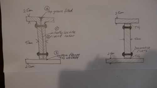
And another option comes to mind…. just to machine the shapes out of solid bar. I think that I will try TIG first.
Later…. just remembered. I don’t have any TIG gas. Easter. Bum. OK. Back to square one. Maybe I will try to mill the shape from bar…..

Hi John, following with interest your Armstrong cannon project. I would consider using C section back to back and modified accordingly. If you have a pan break bender that with take 2.5 sheet it wouldn’t be hard to bend the section required with a cut in the flange to get the tapered lengths, then mig or tig the cuts (less distortion). Being a bit of a purist, maleable iron rivets would be the go.
Incidently, the triple marine engine of mine sort of runs O.K in either direction but a bit lumpy. Have fitted a variable speed electric motor, that saves messing about with air compressors or steam for demo runs.
Have fun, Self isolation in the shed is no hardship!!
Chris from Albany, W.A.
LikeLike
Hi Chris, 2 problems with C section. There would be a groove top and bottom which would need filling, and then camouflaging with paint or something. And I cannot find a supplier of the right size. 50mm is the closest, but not quite right. C section was my first thought, but I have moved on from that. Will try milling from solid bar first.
Maleable iron rivets sound good but I couldn’t see any of the right dome head shape on Ebay. Will look again.
Your triple. Is it run in? Does it have a flywheel? Have you you tried it on steam? It should run well just on the HP if it is timed well.
regards, John
LikeLike
Hi John, Thanks for reply. machining your chassis girders would certainly give the best results and probably be quicker than fabrication what with the setups, welding, distortion and finishing ops. No doubt you have tried E.J. Winter for the rivets, of course you could machine your own up (an unenviable task!). On the subject of silver soldering m/s, I too have had issues, it seems the grade of steel plays a great part in success or a mess.
Triple is well run in, there is a flywheel but it may not be big enough. Marine engines did tend to have small flywheels due to the gyroscopic effect on the ships. I have sent some pix to your email, hope you receive them.
Have a great day, Chris
LikeLike
And the propeller and shaft acted as a large flywheel….. Did not look at EJW… will do so. John
LikeLike
Hi John
Some time back you responded to a question I had regarding the alignment of the triple expansion engine columns and the bedplate. I have just reread your post showing the use of an aluminium jig. Do you still have this jig and and is it now surplus to your requirements? If so would you be willing to allow me to purchase it, as this would save me a good deal of time and effort in procuring the material and making one?
Kind regards
Roy Armstrong Altona Vic
LikeLike
Hi Roy, I am not sure if it is still there. Might have been reused for something else. If it is there and intact you are welcome to it. Will check tomorrow. John
LikeLike
Hi Roy, I found the jig. It is useable, but will need a cleanup. It has been used for other projects since the triple, so has some interesting patterns, but there are enough flat surfaces that it could be used to space the columns and locate them on the base plate. Send your address to jviggers@iinet.net.au and I will post it. No charge. Just send it back when you are finished with it. John.
LikeLike
Hi John,
Would you be able to share the 3D CAD drawing of the cannon model? For my final year project, the 3D CAD drawing would help reduce some of my workloads.
Warmest Regards,
WeiTeng
LikeLike
Hi WeiTeng,
I am considering writing up the construction and plans for publication, so it would be unwise for me to share them at this time. Sorry. Best wishes for your project. John
LikeLike
Hi John,
Appreciate your fast response. Do let me know if there are any changes. Many Thanks.
WeiTeng
LikeLike