johnsmachines

machines which I have made, am making, or intend to make, and some other stuff. If you find this site interesting, please leave a comment. I read every comment and respond to most. n.b. There is a list of my first 800 posts in my post of 17 June 2021, titled "800 Posts"

Tag: CNC mill

Rifling the Model Armstrong RML

P1053702

The HSS cutter is mounted in a tight 3mm wide slot in 16mm silver steel.  The 4 mm cap screw pushes the cutter up by 0.2mm per full turn of the screw.

The following video shows an air cut of the rifling cutter in the CNC rotary table on the CNC mill table.   Then some actual cuts in a 1:10 scale cannon barrel.  This barrel was a reject, and was used to practice the rifling cuts.

You can click on the arrow in the box below, or see the video full screen in YouTube.


CNC Mill Upgrade – 7.

2 steps forward, 1 step back.   That’s what this project is experiencing.

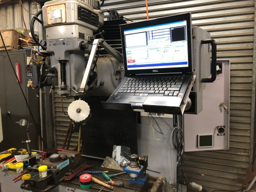
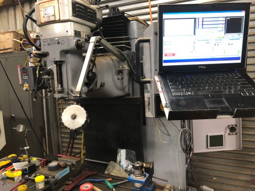
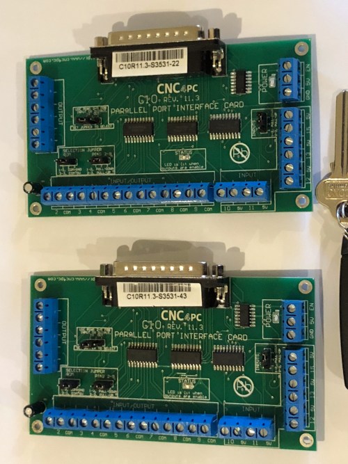
The axis servo motors, their controllers and connections to power, breakout boards, and computer connections are complete, and all working.

An old laptop has found a use.  Installed Mach3, Vectric V-Carve Pro.   And the connections to the Smooth Stepper board.  Windows 10.   Deleted all non CNC related programs to gain space on the hard drive.

A problem with the main spindle.  It is essentially unchanged from the original.  Same motor (4kw/5hp 3 phase), same VSD, and same 3 phase power which is supplied through a phase changer, because the property has only 2 phases supplied.  When powered up, it worked, but the RPM’s could not be altered from a very slow rate.  The controlling voltage from the breakout board was not changing despite changing the inputs.  ? due to a problem with the settings, or a faulty BOB.  Didn’t seem serious.

So I was a bit surprised when later I switched on the mill, intending to change some settings, to hear 2 significant pops, and to smell that disgusting burnt electrical component smell, with smoke coming from the electrical enclosure.

Quickly shut everything down, and waited for the cavalry to arrive.

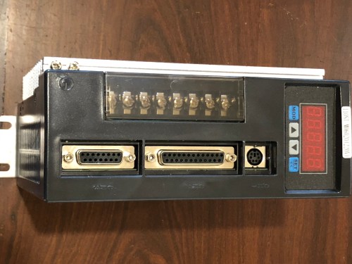
Stuart found that a 24v power supply had failed.  No big deal.  Not an expensive component.  Maybe got a short circuit from a bit of swarf?   But further inspection revealed that the VSD had also failed.  A capacitor and diode burnt out.  ? caused by a surge from the failing power supply? Repairable, but I decided to buy a new VSD.  The failed VSD is probably as old as the mill (24 years), so it had a pretty good run.  If the old VSD is repairable, it will serve as a spare.

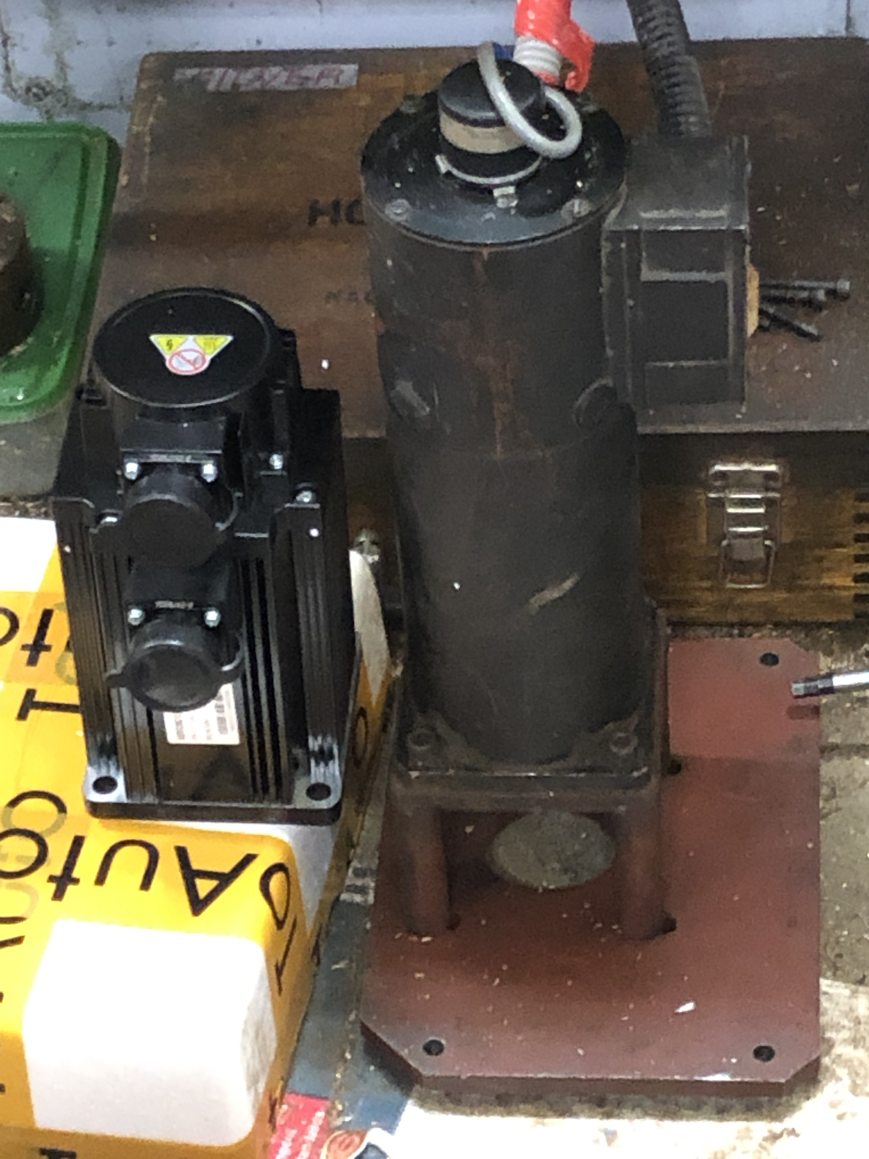
Meanwhile, as a consequence, the main spindle is not working.  I have a list of jobs that I want to get into, particularly the steam pump for the vertical boiler.   So I will reattach the high speed spindle and use that.  It is 2.2kw, but uses high revs to develop power, so I will be limited to small end mills and drills, until the new components (VSD and power supply) arrive.  The high speed spindle is single phase, and the speed control is manually selected.   Not quite as convenient but useable for the time being.

While Stuart has his head buried in the electrical enclosure, I have been his gopher and TA.  But also fitting in a couple of other jobs which have been on the “to do” list for ages.  Like clearing out rubbish from the workshop, tidying up etc.

One task which has been vexing me, was to remove a sheet of flooring board which was under the Colchester lathe.  The sheet was originally placed under the lathe to protect the vinyl floor covering, but it was not a good decision.  As the flooring board became wet with cutting oil and coolant, it would swell and shrink, and I was aware that the lathe levels and settings were changing.  So I decided to remove the sheet of flooring, and let the lathe feet sit directly on steel pads on the vinyl/concrete floor.

But how to remove the sheet of flooring from underneath the almost 1 ton lathe?  The lathe was originally placed into its rather tight position with a forklift, which is no longer available.  The wooden sheet was the same size as the base of the lathe.

So I made these…

img_8146.jpg

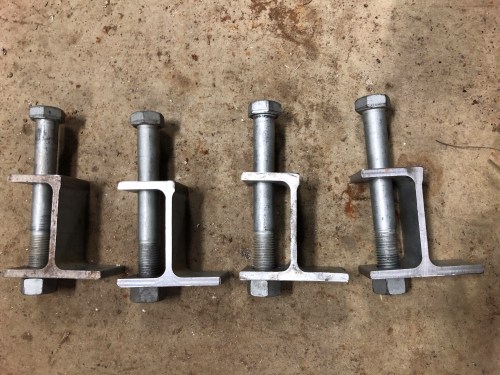
The bolt adjusts the height of the jack.

IMG_8142.JPG

From a piece of scrap I-beam.

I used a crow bar to raise the corners of the lathe enough to place the jacks into position.  A bit of trial and error to get the heights correct.    When the lathe was about 25mm clear of the flooring, I pulled the sheet out.  Then used the crowbar to remove the jacks, and lower the lathe onto its base plates.

I will reset the lathe’s screw feet in the next day or 2, using a precision level and test cuts.  There was an excellent YouTube video by “This Old Tony” on the subject recently.


CNC Mill Upgrade – 6. Where to put the computer?

Not much more to report today, but I have decided how to position the computer.

Not easy, because the computer needs to be protected from flying swarf and coolant spray from the CNC mill and the manual mill which is immediately adjacent.    And I want the computer to be close to the machine.  The CNC mill is NOT in an enclosure.

So this is what I have decided….

IMG_8128.JPG

The laptop is just low enough to reach while standing.   The E stop and other buttons are underneath.

And if the swarf is really flying, I can turn the PC away…

IMG_8129.JPG

Might need some adjustments.  The laptop is an old Dell ATG.   Said to be resistant to fluids and relatively resistant to shock/vibration etc.   Military specs.   I might add some side protection and perhaps a roof.


CNC Mill Upgrade -2

The major components arrived this week, from China and USA.  Switches, and other components which go “ping” will be bought locally as required.  I am hoping that existing pulleys, belts, brackets will be adaptable.

The motors to drive the X, Y and Z axes are 1.2kW AC servo motors which can be connected to single or 3 phase power.  Each one weighs 6.7kg (14.7lb) .  From China, they are nicely finished.   Substantially shorter than the old servos which they are replacing and slightly larger diameter.  I am hoping that the slightly larger diameter will not cause major problems.

IMG_8088.JPG

AC servo.  There are 3 of these.  Kitchen knife to open the box and for scale.

IMG_8115.JPG

Old Y axis servo on the right, and the new AC servo left.


And each servo motor came with a controller and cables and connectors.

IMG_8093.JPG

And the electronics came from USA.

img_8096.jpg

C11 breakout board.

img_8097.jpg

C10 breakout boards x2

img_8098.jpg

And the Smooth stepper control board.  It is tiny, but the most expensive electronic component.

All up cost so far is ~$AUD2100, of which shipping is about 25%.

Next step is to swap over the servos.  The old shafts are 16mm and the new ones are 19mm.  I intend to machine the bores of the pulleys.  Hope there is enough meat  Tofu to allow that.

CNC Mill Upgrade

I was not planning any more major projects for 2019, instead intending to finish the triple expansion engine, the beam engine, the vertical boiler, and the CNC rotary table.

But… my hand has been forced.

The Y axis on my CNC mill has been a bit unpredictable for some months, and on my return from UK, it has totally stopped working.  It seems to be the encoder on the Y axis servo.  I could just repair or replace the encoder, but after discussing the situation with my expert advisor Stuart, I have decided to replace all of the electronics in the mill.  New axis motors, new breakout board, new drivers etc.  It is a 1997 model, and this is the second electronic failure this year.  Plus, it is only a 2.5 axis mill.  It will move in only 2 directions per move….   XY or XZ or YZ,  never XYZ in a single move.   Plus I would like to add a rotary axis, making it a 4 axis machine.

The in built computer in the mill has a 7k memory.  That’s correct, 7000 bits.  I have an external computer linked to it, which makes it a bit more useful, but the Fagor controller is clunky and idiosyncratic, and I would like to switch to Mach 3.

So, I will document the upgrade as it happens.  The mill is a good solid machine, with big ball screws, and 1000mm of x travel, 450mm Z and 450mm Y.  It is worth spending some money on it.  There are a lot of big, old, CNC machines with obsolete electronics out there for sale.  It will be a project which might just be worth watching.

Showing the handwheels for XYZ axis movements, including the broken X axis handwheel


1779 Naval Cannon Scale Model

It is almost 2 months ago that I started this model.

I thought that it would take 3 or 4 days!

Anyway, here it is.

It will look interesting on the mantelpiece.

cannon - 3.jpg

Note the hinge and square bolts and keys on the trunnion straps.

cannon - 4.jpg

A good view of the elevating apparatus, the quoin.

cannon - 6.jpg

A trunnion, trunnion band, trunnion bolts and key.

cannon - 7.jpg

Powder pan and touch hole.

cannon - 8.jpg

The underbelly

cannon - 2.jpg

It goes on display at the Geelong Wooden Boats Show next weekend.


24 Pounder Naval Cannon

A half day in the workshop today, and the naval cannon carriage is taking shape.

cannon - 1.jpg

The pieces at this stage, just push together.  A few more bits of ironwood to be machined, then for the fun time… machining the cannon barrel.

cannon - 2.jpg

Ironwood cannon carriage, sitting on an ironwood kitchen table.  SWMBO is impressed! “it is looking interesting!”  Wait until she sees the brass bling.

Problem with Balls (Incarcerated ball bearing)

The X axis on my NC mill was always noisy in operation from the time I purchased the machine a year ago, and the seller told me that he thought the end bearing was the source of the noise.

In comparison, the Y and Z axes were almost silent in operation, swishing to their allocated positions.

But the machine worked well and accurately, so I did not fuss about the noise.

But a couple of weeks ago, the X axis low pitched rumble changed to a louder, more graunchy sound, which I did not like at all. However the accuracy was still not affected.  And the noise occurred only with rapid feeds.  On machining feeds, it was not noticeable.

So, with some trepidation, and only a vague notion of the construction of the machine, I disassembled the suspect bearing.  That involved unscrewing covers, unbolting the heavy servo motor and lifting it to the floor (not wise.  my back still aches.  next time I will use a supporting jack or platform), then trying to figure how to remove the toothed pulley.  A phone call and text message including photo to my expert friend (thanks Stuart) gave me the necessary information how to remove the tapered bush and pulley.  I made a simple gear puller which screwed into 2 threaded holes in the end of the tapered bush, and the whole lot magically came apart.

The bearing housing, toothed gear and tapered bush.

The bearing housing, toothed pulley and tapered bush.

Removed the toothed belt.

The bearing housing was next, secured by 5 large cap screws.  But it would not budge, despite removal of the screws.  The 2 locating pins were tightly ensconced, and persuasion was required with a series of slim wedges, hammered into the gap.

I took the cleaned up housing containing the bearing to Bob Hamilton’s Bearings and the expert there explained that there were actually 2 bearings pressed into the housing.  These were angular bearings, facing each other.   I thought that he would be able to tell me if they needed to be replaced, by the feel of them.  Unfortunately, he explained, the only way of knowing for sure, is to actually replace them, and see if the problem is fixed.

The replacement bearings would have to be ordered at a cost of $au100, but should be delivered within 24 hours.   Since my machine was out of action and of course I was in the middle of a job, I decided to insert the new bearings.

Sure enough, they arrived the next day.

A bit nervously, I pushed out the old bearings.  I made up a brass pusher to the size of the opening, and the bearings slid out fairly easily.  So far so good….

The reader should be mindful that a retired gynaecologist does not have a vast experience of changing machine bearings.

I carefully noted how the bearings were asymmetric, cleaned the cylindrical cavity and my hands, set up the press, and pushed the first bearing home.

No problem.

Except that the bearing was back to front!

Despite my careful noting of the configuration, I had managed to get it wrong.  Stupid stupid stupid.

And there was now no access to the outer race of the bearing to push it out!

What to do?

I have heard of using frozen carbon dioxide to shrink bearings and make removal easier.  But I have no idea how to access CO2.

The bearing slid in easily enough, so would it matter that much if I pushed on the inner race to get it out?

Oh well.   WTF.   If worse comes to worst I will fork out on another bearing.  But maybe with a separate supplier.  Just to save  much embarrassment.

So I pushed on the inner race.  It took more pressure than getting it inserted.   Then bang!

The inner race, the ball cage, and the balls, popped out.   I retrieved them all.  Fortunately the balls were sizeable and easily found.

But the outer race was still stuck in the housing, and what was worse, there was no edge to push it out.  Nor was there a gap at the housing base.  The race was still pushed firmly home.

F**k,  f**k, f**k.!!

CO2 option??   Same problem.  No idea how access it.

Drill some holes through the housing to allow access for a pin punch?   Ugly idea but might work.  Keep that one in reserve.  I really did not want to risk weakening the housing.  The machine is 18 years old and I am certain that such spare parts would not be available.

Maybe I could somehow lever the race to create a gap at the base and get it started.   But no access, and did not want to risk damaging the housing.

So, to cut this story short, I turned a steel disk about 5 mm thick, with a 25mm central hole,  and outside diameter just to fit into the housing through the race.  The disk had a knife edge.  I cut the disk, to enable it to be expanded.   Inserted it into the point of contact between the race and the housing, then expanded it using a pipe expander.  I could have used a tapered bolt, but the pipe expander worked.  As it expanded, it pushed into the slight groove between the race and the housing, then I felt the race move a little.  Some further expansion, and it moved some more.  Then, hallelujah, the race popped out. (I will insert some pics tomorrow).

The Pics.  (added 16 Sep 2015)

The pipe expander.

The tube expander.  Usually used for joining copper pipe.

The knife edge, split ring, used to dislodge the bearing race. (seen here in its expanded state.)

The knife edge, split ring, used to dislodge the bearing race. (seen here in its expanded state.)

Another view of the knife edge split ring, in its expanded state.

Another view of the knife edge split ring, in its expanded state.

On inspecting the angle contact bearing, I could see no marks or indentations on the bearing surfaces, or the balls.  So I cleaned the bits, reassembled the balls in the cage with clean grease, and pressed the assembly together in the press.  It all went together with a satisfying “click”.  It seemed to rotate smoothly, so I pushed the bearing back into the housing, then its partner, correctly this time.

After reassembly, I tested the machine.

It worked smoothly, and the X axis is now as silent as the other axes.

I feel stupid that I got the assembly wrong first time, but happy that it worked out in the end.  And a bit chuffed that the expanding, knife edged disk idea worked!  Probably reinventing the wheel.  Not happy about breaking apart then pressing together the bearing.  However if it becomes noisy again I will be more confident about replacing it.

I suspect that the original bearings were not actually worn, but just needed the securing nuts to be tightened.  If I had tightened the securing – compressing nuts, I might have solved the problem.  Oh well, live and learn.  I will keep the old bearings as spares.

24000 RPM spindle for CNC Mill 2

Yesterday the spindle was wired to the Variable Speed Drive – single to 3 phase converter, and to power. It span smoothly and quietly, and very fast.  Much quieter than a woodworking router of similar power and RPM.

Today I hooked up the coolant, after testing the pump.  But when I ran the coolant through the spindle, there was no movement of the coolant.  So I reversed the fluid connections in case it was direction specific, but still no action.

The pump and lines were OK, so there was a blockage in the spindle.

I removed the coolant connectors on the spindle, and I could see something white and foreign deep in the works.  A bit of poking around revealed that it was probably a bit of packaging foam.  I dug out some, then blasted the rest out with compressed air.  Testing with the compressed air showed that the way was now clear, so I reinserted the supplied fittings.

And one of them snapped level with the surface of the spindle cover.  Bugger bugger.

I managed to get the broken buried thread out of the spindle using an “Easy Out”.

The broken fitting looked complex.  I certainly did not want to wait for one from China, and I was very doubtful that it would be available locally.  I could have made one, but it looked like a half day job.

So I silver soldered it!

The top of the spindle.  The fittings, with the broken one on the left.

The top of the spindle. The fittings, with the broken one on the left.

The coolant fitting and its broken thread, fluxed and ready for silver soldering.

The fitting in position for silver soldering. Resting on a nail held in a vice.

IMG_2723

The fitting after silver soldering. The threads needed to be cleaned up by running a die down them

This is the setup during the first engraving job.

This is the setup during the first engraving job. The green fluid is the coolant.

Engraving a small brass plate, at 20000 rpm.

Engraving a small brass plate, at 20000 rpm.

24000 RPM spindle for CNC Mill

IMG_2718

The mill quill and spindle is on the right hand side, with a 1 inch cutter insitu. The high speed spindle and its VSD controller is on the left hand side. Of course the cutter on the rhs will be removed when an engraving cutter is installed in the high speed spindle. The wiring hook ups, and coolant pump and lines are yet to be installed It does not look much but it took me a whole day.  The setup is quite rigid.

Today I spent a few more hours setting up the high speed spindle on my CNC mill.

I will post a video when i am doing some label engraving.

Make Your Own LONG SERIES TAP

My current project is a diversion from the triple expansion steam engine, which is about 33% completed.

I wanted to do some engraving on my CNC milling machine.  It is accurate enough in XYZ movements, but the spindle has a maximum RPM of approximately only 3000.  Engraving with a cutter with a tip of diameter 0.1 to 1 mm diameter really requires 10-20 thousand RPM.

I also have in mind making some wooden things using router bits, and they usually rotate at 12-26 thousand RPM.

I wondered about a manufacturers attachment for my mill but could find nothing.

So I decided to make my own.

I briefly considered attaching an electric  router to the mill, but since many projects require constant spindle work for several hours at a stretch, I decided that the spindle should have an inbuilt cooling system.

What I bought was a 2.2kW spindle, 3 phase, with a variable speed controller, giving an RPM range up to 24,000.  It is designed for liquid cooling, and can be used for long periods without overheating.

The spindle has an 80mm diameter, and I will attach it to the 110mm diameter quill on my milling machine.

So, I cut some holes in 16mm aluminium plate.


IMG_2713

The aluminium plate attaches to the milling machine quill, like this.


To clamp the plates to the quill, and to the spindle, I cut some slits into the holes in the plate, and drilled and tapped some 6mm holes. (done after the above photo was taken).

My problem was that my 6mm taps were all much too short for the job.
I went to my usual industrial tool supplier to buy some long series taps, only to be informed that long series taps are not kept in stock, and would take several days to arrive on special, and very expensive order. Long series taps apparently cost at least 3 times as much as conventional length taps.

Having had success at silver soldering band saw blades, I wondered whether I could add some length to a conventional tap by silver soldering some steel rod, end to end, to the tap.  It was also quite succesful.

Here is the setup for the soldering. (Sorry Americans, what you call soddering the rest of the English speaking world calls soldering).
IMG_2714The angle iron is held in a vice. The tap to be lengthened rests in the angle (after thorough cleaning and application of flux), and the rod likewise (in this case, a cap screw of the same diameter as the tap). The join is silver soldered in the usual manner.

This is what the lengthened taps look like.

I wondered whether the silver soldered join would be adequately strong for the tapping.  the tap was totally buried in the workpiece, and would have been irretrievable if the join had broken, and ruined the workpiece. So I was very cautious when doing the tapping.  Used a tapping oil, and backed the tap out of the workpiece every few turns for cleaning.

I wondered whether the silver soldered join would be adequately strong for the tapping. the tap was totally buried in the workpiece, and would have been irretrievable if the join had broken, and ruined the workpiece.
So I was very cautious when doing the tapping. Used a tapping oil, and backed the tap out of the workpiece every few turns for cleaning.  It worked fine.  It was a demonstration that silver solder is really very strong.

One advantage of using a cap screw for the lengthening rod was that the hex head proved ideal as an attachment for a tapping handle. The tapping handle being an Allen key.

I will post more pics of the engraving-routing spindle when it is finished.

ps. my expert friend Stuart T tells me that silver solder has a similar tensile strength to mild steel!

Machining the columns on the Titanic Engine Model

IMG_2460

Deep drilling using CNC. The last hole was drilled manually, with problems. CNC rules OK!

A warm day today. Too hot to wear a shirt in the workshop. But no metal splinters from machining the brass and aluminium, and only one hiccup, which will be described.
The jig which I started yesterday, needed 9 more accurately positioned holes drilled and tapped M4.
So I programmed the CNC mill, only to discover that there is a limit of 8 holes able to be programmed. So the final hole would have to be separately positioned, and that was the cause of my problem.
Firstly, the 8 holes were deep drilled (30mm deep, 4mm diameter) after centre drilling. All done with the CNC.
All went beautifully. 2mm pecks, some cutting fluid brushed on.
Then I used the CNC to position the last hole, and centre drilled it manually, AND BROKE THE CENTRE DRILL IN THE JIG!!!
I did not want to remove the jig from the vice, because it was all accurately set up. But I could not see the broken high speed steel tip, so I removed the jig, and tried to dig out the broken tip. Unsuccesfully.
So the next method was to use an old carbide end mill, 4.5mm diameter, to drill into the hole and to break up the high speed steel fragment. That method worked, but at the cost of enlarging the accurately placed but incompletely drilled hole. Next step was to reposition the jig in the milling vice, then deeply countersink the hole, then complete the 4mm drilling operation. It seemed OK, but it later became obvious that the hole had moved about 0.5mm from where it was intended. I eventually used a carbide end mill to enlarge the entire hole, in the correct position, at 4.5mm diameter.  All a bit messy, but not fatal.

IMG_2464

The jig halves opened up, and the drilling positions which were entered into the CNC instructions.

Then the columns were drilled and tapped.  2 attachment points per column, so with 3 holes per column in the jig, there are 2 possible positions for each column in the jig.

IMG_2467

The columns to be attached to the jig.

A column on the wedges in the milling vice, rea

A column on the wedge in the milling vice, ready to be drilled and tapped.

IMG_2469

The columns screwed to the jig.

IMG_2470

2 columns are integrated with the condensing unit.

Re “Titanic” engine heading…   I get a lot more hits on this blog if I include the word Titanic.  OK?

IMG_2472

Now that all columns are attached in their final position on the jig, I can start hacking into them to produce some flat surfaces

IMG_2475

The columns sitting on the base in their correct position, using the jig.

IMG_2474

LP is the column for the low pressure, biggest cylinder. HP is the column for the high pressure, smallest cylinder. IP is intermediate. C is for the steam condenser.

A JIG for Machining the columns of the triple expansion marine engine

At last!

A day on the steam engine.  SWMBO went to Melbourne to choose marble so I was free!!

After discussing my problems with machining the triple  expansion engine columns with the senior members of the GSMEE (Geelong Society of Model and Experimental Engineers),  I have machined a JIG to assist with this issue.

The JIG thickness is precisely the width between the columns (30.05mm).  It is made in 2 halves so I can bolt the columns from their critical surfaces which are the con rod slides.

I will use the CNC mill to drill the holes in the jig, and the matching columns, then finish milling the columns which are attached to the JIG.

IMG_2457

The jig for machining the columns. Not yet finished.


Bottom left is X=0, Y=0.  The photo shows the 4 countersunk M4 screws.

The holes will be centre drilled then through drilled 4mm. The columns will be drilled 3.3mm then m4 tapped.
Hopefully that will happen tomorrow if the workshop is not too hot.

You will see what I am intending with the next post.

CNC Mill 11

CNC.  That is what started this post.  Today, I fired up the CNC mill, and made a simple fitting for my Bolton 7, which involved some accurate deep drilling in aluminium.  I LOVE CNC!!  Drilling 3mm diameter holes through 16mm material, automatically, centre drilling, then deep drilling  1mm peck at a time and automatically clearing the chips, with positional accuracy of  0.001mm.  Fantastic!  Cannot wait to get more into this.

IMG_2383 IMG_2384


CNC MILL 9

IMG_2068
Yesterday I cut some metal on the CNC mill for the first time.
I used one of the canned cycles built into the CNC controller, and faced and squared off a lump of brass which will be used for a hot air engine (The Ridder “bobber”).
Despite multiple readings of the manual, I got confused about which units required minus signs, and which ones the machine automatically assumed were positive and negative, and consequently, despite resting my hand on the emergency stop button in case such a contingency occurred, the head crashed straight into the milling vice, breaking 4 carbide tips and leaving a permanent love bite on the vice as a reminder of my incompetence.
After some expletives deleted, I re-entered the numbers, and next time, the machine went through its motions gracefully, purposefully, and quietly, leaving me with a nicely shiny and squared lump of brass.
It was so impressive, that I repeated the exercise, just for fun.
I had checked the squareness of the mill head to the table, and it was all within 0.01mm in 100mm, so nothing was altered.
I had bought a Z axis probe from CTC Tools in Hong Kong, and that was easy to use and accurate, for $a100.
Next step, to hook up a computer and try to download G code programs. Watch this space.

CNC MILL 8

Another day, another problem solved….
I am sure that these ramblings are incredibly boring to everyone, so understand that I am recording them for my own benefit, as a diary, as much as for the interest of anyone else who might be thinking of leaping into buying an older CNC mill.
So today I looked at the lubrication pump.
The manual says that it operates automatically on machine startup, then every 30 minutes, as long as the oil pressure is not too high. But the pump showed absolutely no sign of functioning at any time. And the ways and ball screws were totally dry until I lubricated them with an oil can.
Today I spent hours tracing wires and looking at relays, until my friend Jason S, who is a machine designer, came and had a look for me. He put a multi meter on the wires, and everything seemed intact. Then he identified the appropriate contactor (which I gather is really a big relay), and held it in, and lo and behold the pump worked. So the problem was with the pump controlling mechanism. Then Jason surmised that if he had designed the mill, he would have had the lubrication pump working only if the ball screws and ways were actually in use, not just if the machine was switched on. So next test was to watch the pump with the ball screws activated. Lo and behold the pump worked! So what was the problem? Why was the oil not coming through?
We disconnected some oil lines, and they were dry. So we manually pumped the lubrication pump until the lines filled, (i.e. primed them) and tried the lubrication system again, with the axes working, and it worked!

So the bloody manual was misleading. The lubrication system does not work when the machine is switched on. It only works when the ball screws are operating. And the machine has been out of action for so long that the oil lines had dried out.

Another gripe with the manual, was when I tried to get a canned cycle working (dry run, with no work piece or cutter). I followed the instruction steps exactly, and nothing happened. I retried, with the same result. I tried another canned cycle… same result. Then Jason arrived, and followed the steps.. same result. Then he said “what is that DATA button for? I had no idea. It is not mentioned in the manual. So we tried pushing it, and halelujah, the canned cycle worked.
So why was it not mentioned in the manual ?????
Do people who write manuals, ever test their own instructions? Or try them with an end user???
So bloody frustrating and such a waste of time.

(note added a few days later… I found the DATA key described in a different section of the manual. My mistake, it was there all of the time. If I had read the manual from start to finish entirely, and remembered the entire 150 pages – or whatever – I would not have had the problem. Silly me. )

Anyway, another step towards making some chips.

So now for the final test, the hookup with a computer using a serial port. Fortunately I have an old computer with a serial port, and I will hook it up soon.

CNC MILL 7

Z axis problem fixed!

My friend Stuart T methodically checked the wires and connections, and diagnosed a problem involving the Z axis encoder.  He  resorted to removing the encoder, to look at it more closely, and said ” that came off a bit too easily.  I wonder if the shaft is connecting properly”.  Sure enough, the shaft was loose, which explains the bizarre Z movements followed by a total loss of position information.  Someone has joined the 6mm shaft to a 1/4″ socket, and it had probably worked loose during the transport from Echuca to Geelong.

So we quickly made a sleeve to join the 6mm shaft to the 6.35mm socket, tightened it all up,  soldered a few wires which broke during the inspection, and hooray it all worked perfectly. Hallelujah.

Oh, and that $20 Chinese hand wheel.  It was 10 mm thicker than the originals, and looked out of place, so I chucked in the the lathe, and turned it down to the same 18mm thickness  as the originals.  It was made of hard plastic-bakelite material which smelled really offensive while I was machining it, and was very abrasive.  Tool steel lathe bits were just worn away, but a carbide insert tool coped OK.   The reshaped hand wheel  looks and feels much better.

Just the oil lubrication pump to fix, then I can start making chips.                                                                                                                                                                                                                                                                                                                                                                               


CNC MILL 6

Help!

I need a wiring diagram for the Extron mill.

It is a Hafco badged machine, but Hafco (Hare & Forbes) do not have wiring info.  The Extron factory in Taiwan has not replied to my emails.  Hare & Forbes apparently contacted the factory, and also drew a blank about wiring info.

That is pretty unimpressive.  The machine is only 17 years old.  In built obsolescence?  Just not worth while supporting older machines?  If it was a US or European machine there would be no problem getting info.  It seems that this Asian factory has a different idea about what constitutes support.  

Fortunately I have an expert friend who will, I am confident, be able to work it out.  


CNC MILL 5 with some more pics

The broken X axis hand wheel.  replacement from China for $a20, including postage....

The broken X axis hand wheel. replacement from China for $a20, including postage….

The replacement folding handle hand wheels arrived from Hong Kong today. I was slightly disappointed in the quality, but then, for $a20 each, including postage, I am not complaining. They are close in appearance to the originals.

IMG_2040

The new hand wheel fitted. On the table is a spare new hand wheel, and the broken one. I am considering machining the new one, to be closer in dimensions to the old one.

IMG_2037

This is the pneumatic draw bar motor and spring loaded engagement gear. It is now functioning!! I rebuilt a badly corroded valve, and remade a gasket, and hooray, it works perfectly. Still to replace the cover which keeps the dust out of the device. That saves $a700+ for a replacement, and gives me confidence to work on these precision items in the future. The motor behind the draw bar motor is the main spindle motor, a 6hp 3 phase motor with a very noisy fan which is another job for down the track. One thing at a time. We are getting there. I have contacted Extron Corp in Taiwan, in the hope of getting a wiring diagram, so I can look at the oil distribution pump and controller and locate the relay, which I suspect will be the culprit. It does feel good to have fixed 2 of the 5 or 6 problems with this machine.

CNC Mill 4 (with some pics)

Now that I have a couple of days cleaning off the carelessly applied paint, I am prepared to show some photos.
The trouble with a 17 year old machine, even if it has done little work, is that repairs are required before it can be used.
1. New hand wheel
2. Z axis acting strangely. ? encoder faulty, or broken wires.
3. Pneumatic drawbar not working ? needs replacing.
4. Auto lubrication system not functioning. ? relay faulty, other problem.
5. Operator needs considerable training.

The only available space in my workshop was in front of the door

The only available space in my workshop was in front of the door

Showing the table, with the tool rests removed, the hand wheels including the broken X axis hand wheel, the turret and the electrical box

The broken X axis hand wheel.  replacement from China for $a20, including postage....

The broken X axis hand wheel. replacement from China for $a20, including postage….

Showing the X axis ball screw, the hand wheel gearing, and the coated way (? Teflon)

Showing the X axis ball screw, the hand wheel gearing, and the coated way (? Teflon)

The control box for the pneumatic power drawbar (not working), and the automatic lubrication pump and reservoir (also not working).

The control box for the pneumatic power drawbar (not working), and the automatic lubrication pump and reservoir (also not working).

The CNC input control panel.  I am still learning how to use this.

The CNC input control panel. I am still learning how to use this.

CNC MILL 3

Pneumatic draw bar. The draw bar was not functioning at all. One of the valves was completely corroded, so I rebuilt it, making a new rim from brass and attaching it with Locktite. The draw bar now functions, but it leaks air badly. A gasket needs replacing, and I will renew that. But if it is still unusable, I will buy a new air draw bar.

I turned on the mill for the first time today.
It booted up, and self tested OK. The servo motors and spindle work fine, and smoothly. The axes move up to 4000mm per minute. The spindle runs quietly up to 4000rpm. (not immediately. I ran it for 10 minutes at a low speed as per the instructions). There seems to be some limits to the travel on the X and Z axes, not related to the hard limits. There must be some soft limits set incorrectly.

All of the ways were dry. There is an automatic oiler, with plenty of oil in the reservoir. I used an oil can to lube all of the ways and the ball screws, because I am not sure if the auto oiler is functioning. It is meant to operate on startup, and then every 30 minutes. Another item to check.

This mill is an Extron, with 1000mm travel on the X axis, and approx 500mm on the Y and Z axes. It is big (for me) heavy and smooth. I expected that it would need some attention because it has not been used in years. So far the revealed problems have been with the peripheral items and cosmetics, and not the major components or the electronics. So far so good. I will post some pics soon.

CNC Mill 2

I was on call over the weekend, so I had today off, and spent it in the workshop. It was cold. Jumper plus oilskin cold.
I crow-barred the space for the new mill, levelled the mill with a machinists level. One foot was missing so I turned up a new one… 75mm dia, 16mm thick, with a 20mm dia recess to accept the levelling bolt.
Then I started to tidy up the awful paint job, scraping paint off the machined parts, and using my Dremel to wire brush it off plastic parts. Starting to look more respectable.
Then I found a hand wheel control lever stop made from a rolled tube which had broken off at surface level. It was hardened, as I discovered when I tried to drill it out… changed the drill bit to mush. So I used the Dremel with a carbide bit to grind it out. That worked, but it took a lot of time, and I ended up with an irregular hole which I then drilled out to 5mm and tapped 6mm. I have inserted a temporary 6mm cap screw as the stop, and it works but looks a bit gross. Needs a tidy up.
The 3 phase lead does not reach my converter, so I have to replace it with a longer one. The plug is new, so I will re-use that. I have some 20 amp 4 wire lead, so I will use that. Maybe next weekend I will get to fire it up. Saturday is out though. Geelong – Hawthorn AFL game takes precendence.
I need to make some T nuts to suit the 18mm T slots. They are bigger than any machine I have previously owned. I will tap them to accept 12mm studs, rather than the recommended 16mm studs. I already have the 12mm studs, and I cannot see that I will need the bigger ones. If i was to use the table capacity of 900kg the big ones would be useful.

CNC Mill

Today I took a half day off work, and booked a crane to lift my CNC mill off the truck onto a steel plate outside my shed, from where Des and I rolled the 2.8 tonne machine inside.
It has been under a tarp, in the rain, for the last week, so I am happy and relieved to have it indoors. Some surface rust was rubbed off. And I spent a few hours cleaning it up, oiling it, doing minor repairs and getting it ready for turning on soon.
One of the hand wheels has been broken and I have ordered replacements from Hong Kong. The pneumatic drawbar is not working. I have pulled it apart, identified the faulty part, and I will attempt to make a new part.
The mill is too big for where I have installed it. I have removed the side tool tables, but it is still too big. So I have some further crow barring of machines to make space.
I hope to connect it to the electrons in a few days.
It has been repainted at some stage. An awful paint job which has gone onto machined and plastic surfaces. I intend to spend time tidying it up, and one day I hope to repaint it more carefully.
Now I have my fingers crossed that the electronics and ball screws will work OK. It is a bit of a gamble.

New Toy

I have been looking for a CNC milling machine for over a year. My requirements were that it had to be affordable, not too big for my workshop, not too big for my 3 phase converter (max 5hp), use Mach 3, and be in reasonable condition.

What I got was good value I hope, big, 6hp, does not use Mach 3, but I think that it is in reasonable condition.

See photo below.

It is an Extron (Taiwonese) 1997 model, vertical CNC mill, which uses a Fagor controller (not Mach 3), weighs 2.8 tonnes, and is BIG. Too big really, and I hope that I never have to move it again. It required a crane to lift it onto the truck which I borrowed from my neighbour. The truck (and me now, and the mill) smell of pig shit, because that is what the truck was used for the day before. But the 550km round trip to pick it up was completed safely. Now I have to organise a crane at my shed to lift it onto a steel plate outside my shed, from where I can push it into position (on rollers).

That was the longest truck trip I have driven since getting my heavy rigid licence a few years ago, and I feel quite proud to have completed it without a problem.

I will fire the mill up next weekend. Wish me luck.

IMG_1999