johnsmachines

machines which I have made, am making, or intend to make, and some other stuff. If you find this site interesting, please leave a comment. I read every comment and respond to most. n.b. There is a list of my first 800 posts in my post of 17 June 2021, titled "800 Posts"

Tag: making a crankshaft

Making A Crankshaft -10 (Installation)

Yes. As usual, this project has taken at least twice as long as I had planned.

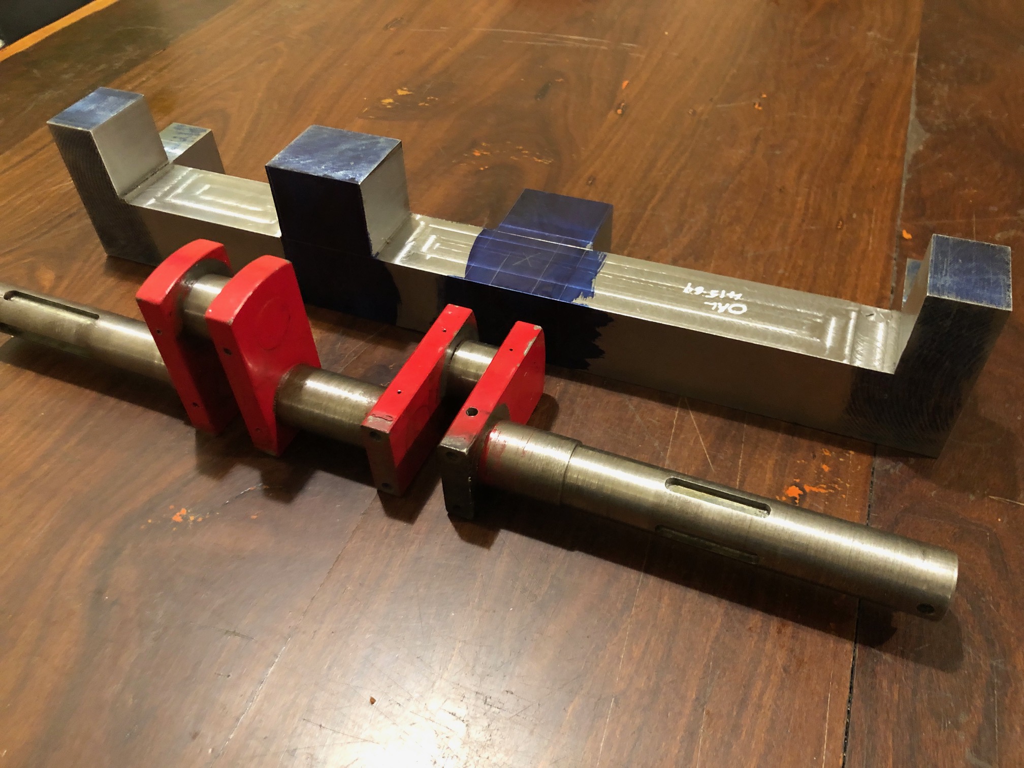
But, the making of the crankshaft has finished, and I have started to install it in the traction engine.

I installed the valve eccentrics, approximately in their correct positions. I had marked the eccentrics according to their position on the old crankshaft. The exact timing positions will be determined when everything is installed.

The crankshaft was placed in the main bearings. I had made the crankshaft with the bearing spacings according to the original plans. Then realized that the original maker had varied some of the dimensions, including the distance between main bearings. So I needed to gain approx 2mm between the main bearings. I achieved that by taking some width off one of the gears on the lathe.

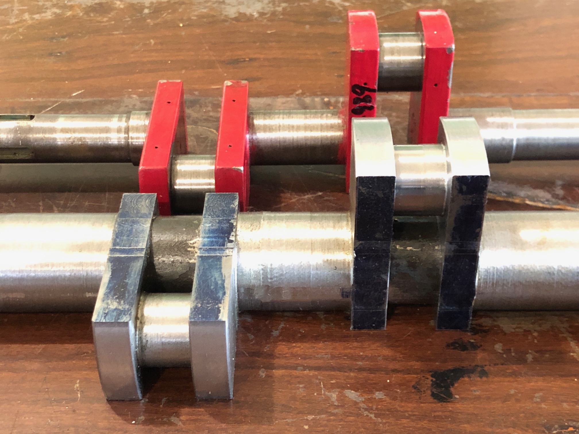
Today, I started to fit the big end bearings. I had deliberately made the big end journals 0.1-0.2mm bigger than the old ones, knowing that I would have to increase the diameter of the big end bearings.

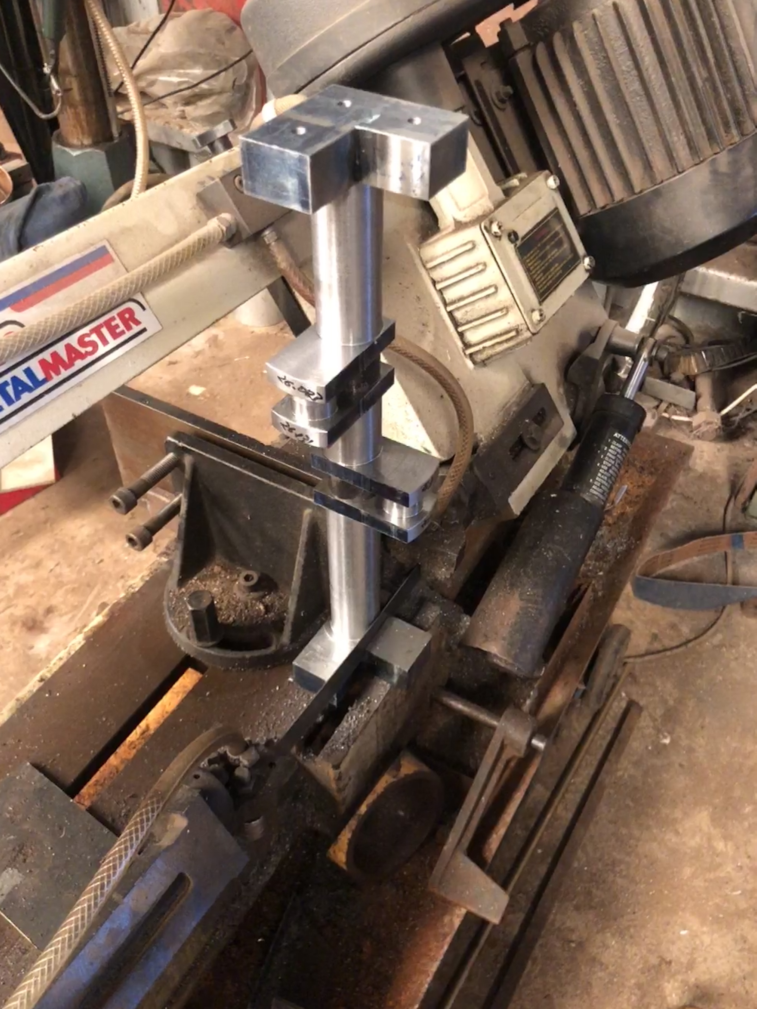
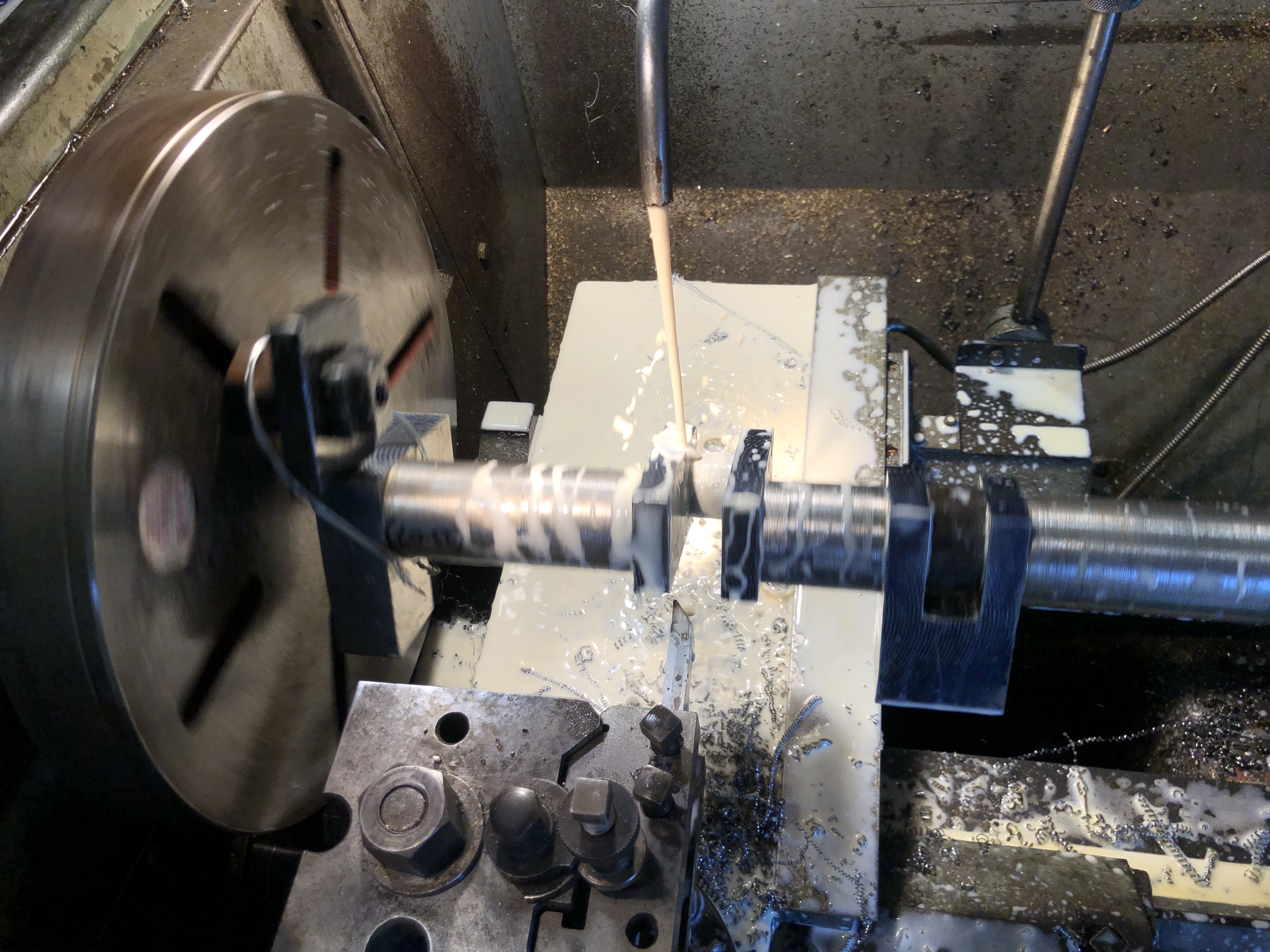
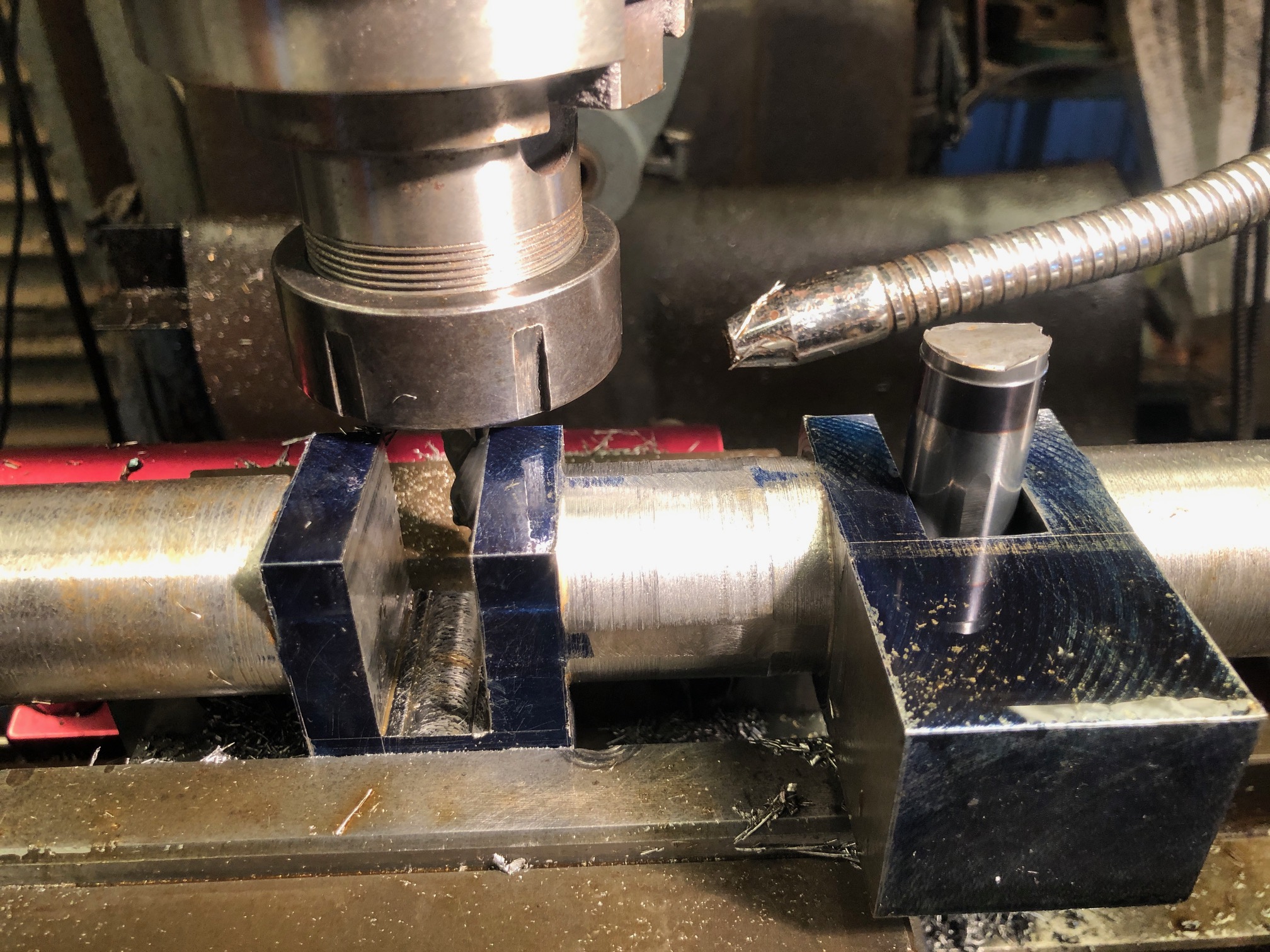
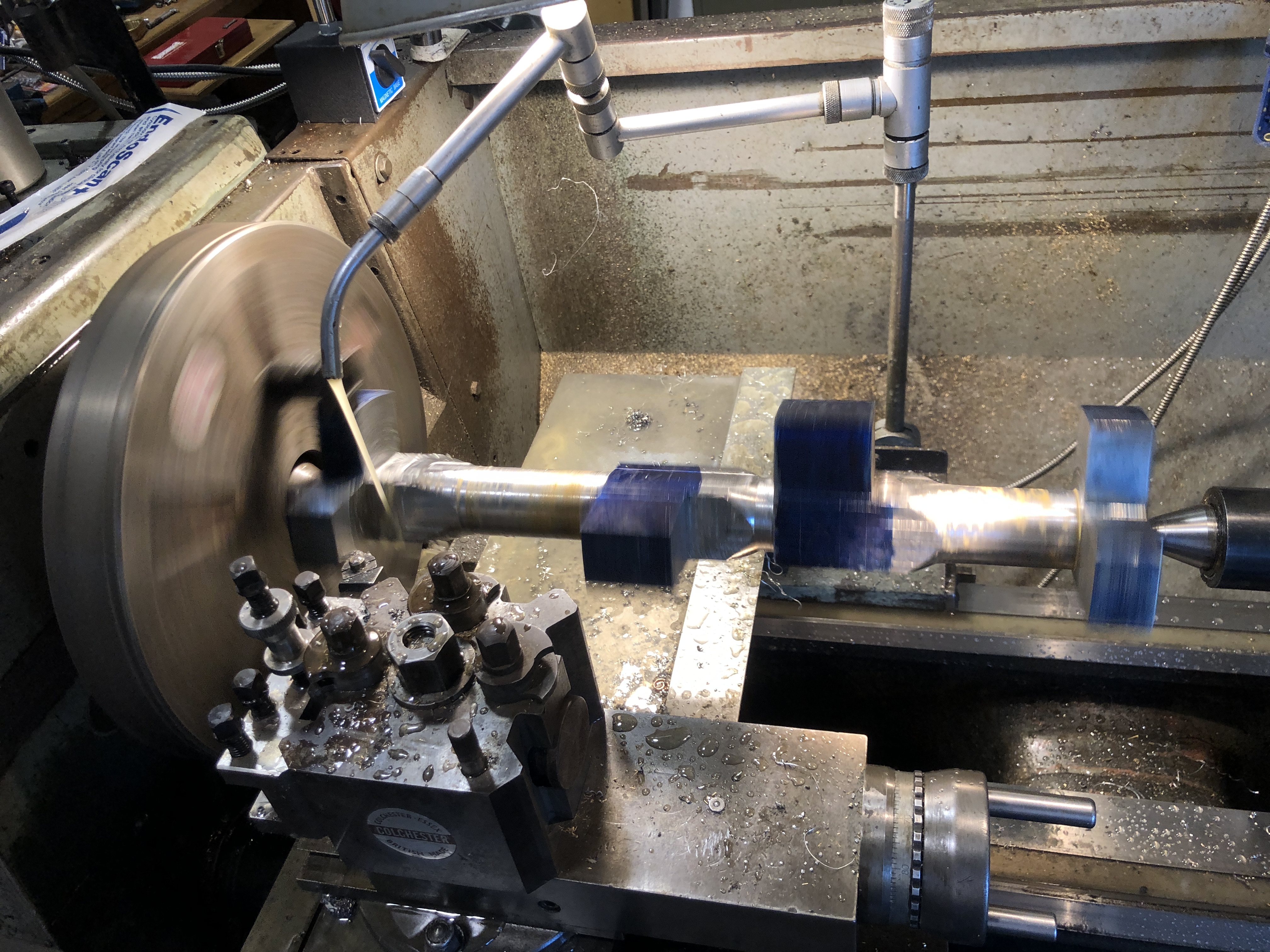
The 3 jaw chuck is holding a smaller independent 4 jaw (because I did not have a suitable backing plate for the small 4 jaw. And I needed a small 4 jaw so the bearing halves would seat on it.). The big end bearing is held in its engine housing, and the original bearing hole was clocked in the 4 jaw as accurately as possible, after tapping it against the jaws with a light hammer. Then the bearing was turned to the slightly larger diameter.

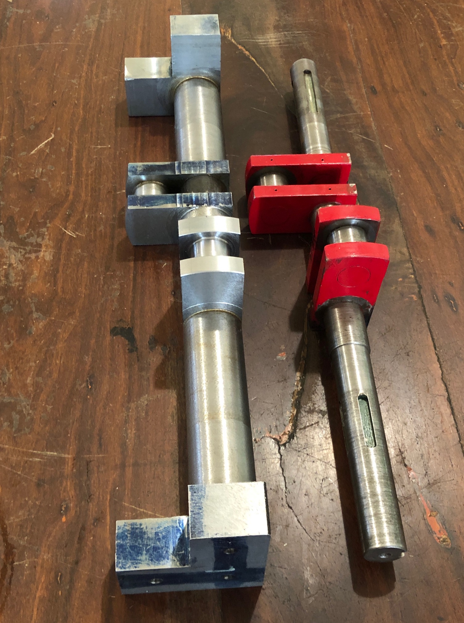
The crankshaft with the main bearings and big end bearings tightened. The eccentric rods are held out of the way with aluminium wire. The shaft turns but it is very tight, and will need further freeing. I have used some “Gumption” but it needs a bit more. Maybe running the engine on compressed air will free it up.

A quick test with the flywheel in position looked promising in terms of run out.

Making A Crankshaft -9

Almost finished.

When turning the big end journals the supporting block for each crank had to be heated to release the Loctite and remove the block, then re-glued in place after the journal was finished.

Then the mainshaft itself was turned.

But first the centres for the big ends were cut off, after making sure that the journals were totally finished!

In this instance I used the horizontal drop bandsaw, because I have not yet replaced the damaged blade on the vertical bandsaw. There is a piece of steel clamped in the vice, and the weight of the workpiece is sufficient to keep it in place during the sawing.

As you can see I used a flood coolant-lubricant. Here getting the dimensions close to final using a tungsten insert tool, at 235 RPM. At that speed balance weights were not required. Depth of cut was 0.5mm, and frequent stops for measurements, so it was a time consuming process. And to disassemble and clean the cross slide DRO glass scale. I reversed the workpiece where required to cut towards the headstock. I still do not know exactly what the steel grade is, but whatever, I had several changes of inserts as they lost their edge.

The final machining step (I hope), was to mill the keyway grooves. That took another 6 hours.

The CNC rotary table was very useful for setting the angles, and locking the shaft in position, on the mill. Two 6mm carbide endmills were required to cut the 10 keyways. Here I used a spray coolant, powered with compressed air. A little less messy than the flood coolant.

The crankshaft is almost ready to be installed in the traction engine. The support blocks to be removed finally. The shaft ends to be chamfered. And the crank weights to be drilled, tapped and bolted in place.

I had marked the eccentrics positions before the original disassembly, and here I have installed them approximately in the same positions on the new crankshaft. Of course they will require small adjustments later. The gears slide smoothly on their splines.

Doubtless there will be installation issues. The old crankshaft deviated from the plans in quite a few respects, and sometimes I was unsure whether to copy the old crankshaft, or to follow the plans. “Copy the old crankshaft” was the general advice, but there were some obvious discrepancies which had to be addressed. I can only hope that I have made correct decisions.

Making A Crankshaft – 8b

During the turning of the big end journals yesterday, the digital display on the lathe stopped showing the cross slide position. So I completed the task relying on micrometer measurements. A more traditional method, but not totally in my comfort zone, being more used to the digital readout method.

Today I investigated to cause of the failure. First I switched the cross slide and longitudinal feed cables on the display unit to see whether the fault was in the sensor component/cable or the display itself. The fault was clearly in the sensor component/cable. These do fail occasionally, and are not horrendously expensive to replace, but waiting for a replacement was going to be annoying since I am in the middle of a very interesting job (making a crankshaft).

Hmm. I wonder if it is a fault which I can fix? I have never taken one of the units apart previously. And it is probably full of springs and bearings as well as a fragile graduated glass slide. But, nothing to lose. So here goes nothing…

Unbolting the scale from the lathe was straightforward, since I had originally installed it. But it was quite a few years ago.

Moved the sensor manually with it switched on. Still no movement on the display.

So I disassembled it.

Unscrewed the end block, and gingerly separated it from the aluminium case.

Then pulled out the rubber seals (the blue strips in the following photo).

The glass slide components, after wiping clean.

Then pulled out the unit with the electronics and the sensor. This was where I was expecting small bits to spring out and go flying across the workshop, lost forever. But no. It came out as a unit.

The board, glass scale, bearings etc were all covered with coolant and tiny chips!

How to clean them? I used compressed air.

Then wiped the glass graduated scale and protective blue seals with a clean microfibre cloth.

Reassembled the unit. Not difficult.

Switched it on.

Hallelujah! It worked!

Note to self. The sensor unit needs to be made coolant proof.

Making a Crankshaft – 8

Finish turned the big end journals today. I decided to make them slightly bigger than the original shaft, because there was a measured deficiency of approximately 0.1mm – 0.15mm (? wear, ? manufacturing error) between the original shaft and the original split bearings.

I had rough milled one of the big end journals a couple of days ago, and Loctited a block into the crank slot of the other big end. I decided to finish turn that journal first, then to remove the loctited block and glue it into the finished crank slot, before rough milling then finish turning the second big end journal. If you follow me.

That all took another half day. And, I experienced my first significant (but not fatal) stuff up in the job.

Copious coolant, 135rpm. Of course the workpiece is centered on the big end journal. Here the tool is approaching the journal to be machined. The packing piece is glued into the other crank slot, and will remain there until the journal being machined is totally finished.

After finishing the first journal and changing the location of the packing piece the second journal was roughed out on the mill. I was much more confident about this method by now, and was more aggressive with the cuts. Used coolant throughout, and the cutter was in good shape at the end. I roughed the diameter to within 1 mm of the final dimension to reduce the time for finish turning. Note the use of my shop made clamp to reduce backlash and vibration. That worked much better than the previous soft wire method.

When I was happy that the journals were finished, I glued in a second packing block, centered the shaft, and turned the curved outside shape on the crank flanges.

As you can see, there is a lot more swarf to be made yet.

Oh yes. The stuffup. After one side of the first journal was turned the insert was blunted, so I rotated the insert. But unfortunately dropped it and chipped it, so it was replaced with a new one. My error was that I did not notice that the tip radius of the new insert was different… 0.8mm radius rather than the original which was larger and made a nice fillet at the join (see above photo). The new insert made a much sharper join, still with a radius, but much sharper. Not fatal, but not ideal.

In the next session I will recheck all of the big end journal measurements. If all are good I will cut off the side flanges at the ends of the shaft, removing those centers for ever.

I will see if my fixed lathe steady will fit into the middle gap between the cranks. If it fits, I will take a smooth light lathe cut of that section and install the steady. Then finish turn both outside sections of the mainshaft. Then move the fixed lathe steady to one of those outside ends, and finish turn the central section. The central section is where the eccentrics are located.

If the fixed steady does not fit in the middle section I will finish turn that section first, after installing the fixed steady on the longest outside section of the mainshaft.

Those possibilities are to keep the mainshaft as rigid as possible during all of those turning steps. (that list is more for my benefit than yours, dear reader).

p.s. So far, there has been no discernable distortion of the workpiece despite removal of over 20kg of swarf. That has been assessed on a granite surface plate, after filing all of the machined edges of all metal tags and lips.

Making A Crankshaft -7

Not finished yet, but the end is in sight. Maybe 2 or 3 more workshop sessions.

Today I roughed out one of the crank journals. I had hoped to do both of them, but had some problems to solve.

Normally big end journals are turned on the lathe. With this crankshaft, the lathe tool “stickout” is over 40mm. And the section is initially square, so the turning would be VERY interrupted. So I decided to try a new method (for me), of converting the square section steel to round section on the MILL. This is the setup…

On the left is a rotary table, powered by a stepper motor. On the right is the tailstock. The heights were adjusted using a height gauge. The Y position was determined with a clock gauge. The vertical mill has a 12mm carbide end mill running at 2000prm. Depth of cut initially 0.5mm. Rotary table is set to run for one complete turn. The stickout of the endmill is about 45mm, to just clear the flanges… the weakest link. I broke another endmill, so reduced the rotation speed, and added spray lubricant. Even so, it was not a secure setup. It improved after I replaced the ziptie with soft wire.

The end result, a “roughing in”, was not too bad. Since the end mill was centered over the journal, then moved to the lateral extents. each cut bulges slightly in the middle. In retrospect I could have flattened the cylinder by creating a final spiral. But since it will all be finished with a lathe cutter, that is irrelevant.

Note the Loctited spacer in the other crank space. I started the same process on that big end journal, spotted the difference, and aborted the process just in time.(!).

So I transferred the crankshaft to the lathe…. and discovered that the toolpost was too wide to permit turning due to collision with the shaft end block.

Here is the turning setup. If the toolpost looks a bit odd, I have removed about 10mm from the near side, to allow clearance. This was a damaged toolpost, so I had no hesitation in modifying it. Note the extreme tool stickout. That is why I wanted to NOT have interrupted turning. So I have not yet tried the setup, but I think that it will work. The journal is currently about 38mm diameter. It needs to be reduced to approx 26mm. Stuart Tankard made this tool, and its left hand companion. Thanks for the loan Stuart! I will proceed gently. And use flood coolant-lubricant.

So, again, not much to show for 5 hours in the workshop! But progress is happening. And this is a fascinating job!

Incidentally, the rotary table stepper motor became too hot to touch during the milling. But it did not falter. Very impressed. I think that it would be possible to do the entire journal shaping on the mill. Maybe next time.

Making A Crankshaft -6

Another workshop session. About 5 hours today. That is about my limit before I need to put my feet up.

Today I hacked into the solid heavy strong shaft, to form the crank web slots.

This is the setup. The workpiece was held in the mill vice. The end pieces were levelled using a height gauge, and supported with adjustable screw jacks.

The carbide cutter was 12.7mm diameter, and flood coolant was used. Each cut was 2.5mm deep.

The 2.5mm deep cuts were extended to 38.1mm. Then the slot was widened to 19.05mm using the same cutter, but taking 19mm depth per pass, and 1mm side cut per pass. The right hand slot is finished, and I used an old broken 3/4″ cutter shank to gauge the width. How did I break a 3/4″ solid tungsten cutter? I don’t remember and don’t intend to.
Old and new line up pretty well. Actually mine are more accurate, according to the plans.
Those deep slots will need to be packed when the big end journals are turned, and also when the mainshaft is finish turned. Otherwise tailstock pressure could distort the crankshaft.

So parted off x2 19mm buttons from some 36mm shaft. They slide into the gaps, and will be loctited in place when necessary.

Finally for today I measured the big end bearings, main bearings, eccentric holes, and mechanical water pump eccentric hole. The bearing holes were all approximately 0.2mm larger than the old shaft size, probably due to wear. They are all close to round, rather than oval. So Intend to machine the new shaft to match the largest diameter of the bearings. If necessary I will ream the old bearings to match the new shaft with a circular shape.

I am a bit apprehensive about turning the big end journals because the work piece will be severely unbalanced. Obviously I will install some balancing weights on the lathe face plate, but then there is the situation of the long stick out length of the turning tool, about 40mm. I am pondering the possibility of using the motorised CNC rotary table to very slowly rotate the workpiece, while converting the square sections to cylinders on the vertical mill. Then finishing the journals on the lathe. Hmm. Might just work.

This is the moment when I allow myself to envy the owners of 5 axis CNC mills, in which a crankshaft is made in the duration of a YouTube video, with perfect results, no mess, just a bit of expert CNC programming. But then… if it was that easy, everyone would be doing it.

You might be wondering why I am posting these updates after each workshop session. Partly it is so the day’s activities are recorded while still fresh in my mind. But it is also my method of keeping a diary, for possible future reference, in case I ever have to make another crankshaft (like for another triple expansion steam engine?).

Making A Crankshaft – 5

Another half day workshop session.

I decided, after advice from several readers, to rough turn the mainshaft.

But first, just in case you were wondering, the kitchen entry stairs are finished, except for a bit of painting.

But just in case kitchen stairs are not your thing, back to the Fowler R3 traction engine crankshaft ….

Today I rough turned the mainshaft.

First I tested and adjusted the tailstock offset.

My method of adjusting tailstock set over is to turn disks at the ends of a 300mm bar between centers, with a very sharp tool, taking fine cuts, and measuring the diameters. Then adjusting the set over and taking further cuts until both diameters are equal.

Then mounted the crankshaft blank between pre-drilled centres…

And turning towards the headstock. This was interrupted turning +++. I took 1mm off the diameter, then as I became adjusted to the machine gun rat-a – tat-tat, gradually increased the depth of cut to 1mm, with a spindle RPM of 175/min. Later I added coolant. Note, I used a ball bearing tailstock centre for the rough turning. I will use a solid centre for the finish diameters.

Then turned the workpiece around and using the same DRO settings, did the other ends towards the headstock. Including the faces of the cranks.

I was not too fussed about actual dimensions. They were roughing cuts, and at 38mm diameter there is plenty of extra material. It should be much smoother machining to reduce the diameters of the cylinders, compared to rounding the square sections.

After getting quite a few opinions about stress relieving the workpiece, after all of this machining, I have decided to take the workpiece up to 600deg c, for 1.5 hours, then slowly cool. Probably unnecessary, since it is black steel, but it can’t hurt. Then I will do the final dimension turning.

p.s. about a week later. No detectable movement despite a lot more material removed. And some further expert advice that heat treatment might actually cause problems. So, given the controversy I have decided to do nothing. ie. No heat treatment.

Making a Crankshaft -4

Not a lot more to show after today’s 5 hour workshop session, but the debulking with the bandsaw and mill is complete. The 26.5kg bar now weighs just over 7kg.

I started to bandsaw the remaining 2 blocks, and was just finishing a long cut when the sawing sound abruptly changed and the cutting stopped. WTF? Examination showed that the blade teeth were still sharp, but the teeth set on one side was gone. I think that there must have been a hard inclusion in the steel which stripped the side set. Whatever, that blade is stuffed. To make matters worse, I did not have a replacement on hand.

So, I had to revert to milling to remove the waste blocks. Just to reiterate, the blocks are 38.1mm x 38.1mm x 180mm so it was a lot of swarf again. But I am now using flood coolant, so the swarf was not red hot, and the 12.7mm carbide cutter survived intact. I was reminded why I normally avoid coolant however. It is VERY messy.

And it took a couple of hours so I reckon that I earned this one.

The remainder of the session was occupied by measuring and marking for the crank cut-outs.

Almost every surface of that solid bar will disappear when the turning in the lathe is done. The only surfaces which remain will be the bar ends, and the square surfaces where the counterweights will be attached, and they will not be visible.

The next step.

Do I cut out the crank slots, or do I rough turn the mainshaft? If I cut out the crank slots then I would install some packing blocks, then turn the mainshaft. I cannot see a significant advantage in either next step. Any thoughts?

Making a Crankshaft -3

Yesterday I showed my model engineering group GSMEE, the bare old crankshaft, and the milled and marked lump of steel from which I am gradually removing all steel which is not crankshaft, and turning it into hot, sharp tiger snake repellant, I mean swarf.

“why don’t you just fix the old one?” (I tried. Unsuccessfully)

“why don’t you TIG weld the joins in the old one?” (possible, but Nah! It would distort, and would require finish turning, and I would probably be unable to use the existing gears, eccentrics, and big ends).

“You are going to get a lot more swarf”. (Yep!)

“What are the crosses for?” (So I know which bits to remove)

And some helpful suggestions….

“Cramp the steel vertically on the CNC mill, and drill the centers using CNC movements” (yep!)

“Machine the journals a bit oversize, and re-machine the bronze bearings because they will be worn, and a bit oval” (yep!)

“Turn between centres. Use a solid tailstock centre, not a bearing type” (Yep!)

“Turn the journals toward the headstock, and reverse the workpiece to complete the other side” (yep!)

And, considerable skepticism that the job would be completed successfully. (Understandable. It IS a challenge. But so far so good).

Today another half day workshop session. About 5 hours.

First task was to center drill the turning centers for the mainshaft and the big end journals. I marked the positions on a surface plate, using a height gauge, but the actual drilling using a center drill bit was determined by cramping the workpiece to a large angle plate, establishing a master face, and using CNC to locate the drilling positions. I was pleased to note that the CNC positions lined up pretty precisely with my measured positions. Then turned over the workpiece, cramping the same face to the angle plate, re-established zero X and Y positions , and drilled the other end. Those center drilled holes will determine the axes for the mainshaft and big ends, which are the essential reference points.
Deeply drilled holes for some heavy, interrupted turning sessions.

But before the turning there is a substantial amount of steel to be removed by other means.

“Other means”.

First I tried milling, using sharp carbide end mills 12mm diameter. After I had broken 2 newish end mills, I thought about other means.

First, I used a bandsaw to make deep cuts. That steel is 38.1mm thick, and the cut is 38mm long. That is the thickest steel that I have ever cut with a bandsaw. I was REALLY surprised how quickly the cuts were made. Each one took 70-90 seconds.

Then I thought about using the bandsaw to make the long cuts, up to 200mm long, through 38.1mm steel. But the bandsaw blade was 25.4mm wide, so I chose to make a milling slot 25.4mm wide to allow access of the bandsaw blade. In the process I broke a HSS then a solid carbide 12.7mm cutter. Expensive.

A bandsaw cut 200mm long, in 38.1mm thick steel. It took 7.5 minutes. Surprisingly quick and effective! But cutting the slot was problematic… broke two cutters.
So, for next one, I just used the bandsaw, making two angled cuts to remove 90% of the waste, then milling the hump out. That was easy. And quick! Way to go!.
After the tidy up milling. That is half of the debulking process. Another half to be done tomorrow. Already the lump of steel is a lot lighter. Currently 10.5kg. The old crankshaft weighs 3.3kg, so still a lot of material to be removed. Just a reminder that the original weight was 26.5kg!

SO. I have formed an opinion about removing waste metal. BANDSAWING BEATS MILLING, HANDS DOWN! (but for finishing, milling wins.)

Making a Crankshaft -2

The first step was deciding which grade of steel to use, and the size and section of steel.

I have made several crankshafts, but only one was from solid steel. The others were all from pieces which were joined with pins and Loctite. And all of them were substantially smaller than the traction engine crankshaft. The solid steel crankshaft was for the model triple expansion steam engine. It had 3 cranks, so was a balanced design. I turned it from stainless steel.

The traction engine crankshaft has 2 cranks, at 90 degrees, so is not a balanced design. It turns relatively slowly, and the balance is provided somewhat by balance weights which are attached later.

I was advised to not use bright steel because of a tendency to change shape when machined, due to relieving internal stresses as material is removed. So I contacted several steel local suppliers about purchasing some black steel solid rod or square section.

The three small circles and black rounded rectangles are an end view of the crankshaft

The red circle with a diameter of 114.3mm is the minimum size of round bar stock if the crankshaft was turned with the mainshaft centralised.

The red circle with a diameter of 107.8mm is the minimum size of round bar stock if all 3 centres just fit within the bar.

If square section stock is used the minimum size is 76.2mm x 76.2mm.

In all cases the length of stock is 416mm.

Since steel bar is sold mainly by weight and grade, I looked for a supplier of square section black bar.

But square section black bar has radiused corners, as in the shape on the left. So, to end up with 76.2 x 76.2mm square section I needed to use 90x90mm with the radiused corners. Long story shortened (mercifully, if you are reading this), I found an engineering works locally who was prepared to cut off a 420mm length, shown in a photo in the previous post. It is heavy!

Next steps will be to mill the ends to 416mm, and 2 long faces to a sharp corner. Then to mark and centre drill the centres for the mainshaft and the big ends (the three small black circles in the diagram above). That will be today’s task.

Later that day…..

Squaring the ends of the 90x90mm lump of steel. Hmmm.. those radiused edges could be an issue…
Taking off 1mm per pass with a tungsten tipped milling cutter.
When the corners were squared, my 90x90mm bar just ended up 76.2 x 76.2mm. I always mark the waste with a cross. Don’t ask me why.
The end result of an afternoon’s machining. That bar is too hot to handle. I will measure it accurately tomorrow.
Oh. And a bucket of swarf after a quick clean up. A lot more to come.

CRANKSHAFT – early steps

The triple expansion steam engine crankshaft has 6 main bearings, 3 big ends, and 4 positions where eccentrics attach.

It is about 240mm long, machined from 50.8mm mild steel rod.

The mains are turned from centrally positioned centres, the big ends from eccentrically positioned “centres”.

The centres were drilled on the CNC milling machine, after the locating the top of the bar

The centres were drilled on the CNC milling machine, after the locating the top of the bar

IMG_2609

The eccentric centres were calculated, and drilled using CNC to get the positions.  The longitudinal scribed line was used to position the other end of the rod.

IMG_2610

Turning between centres, using a lathe dog. This will not be a quick job.

And this is how I would like to make a crankshaft…
https://youtu.be/81UjjSH2iFw