machines which I have made, am making, or intend to make, and some other stuff. If you find this site interesting, please leave a comment. I read every comment and respond to most. n.b. There is a list of my first 800 posts in my post of 17 June 2021, titled "800 Posts"
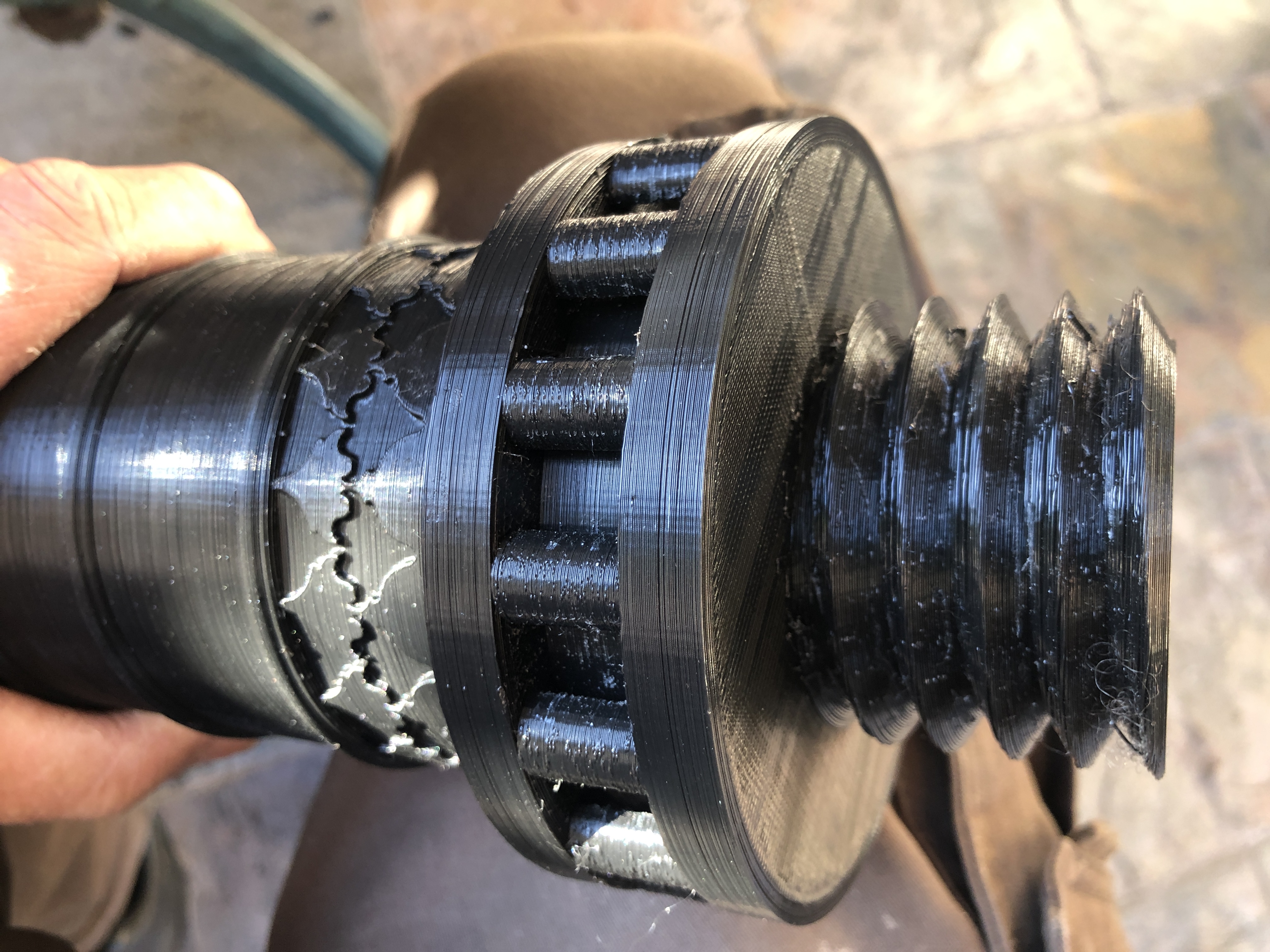
I have given some thought to how to manage the bronze pour for the barrel of the Ottoman bombard. It will be at the size limit of my potter’s oven for the PLA burnout.
The red 3D printed PLA is the barrel. The breech, although significantly shorter, weighs almost exactly the same, but being shorter, should be less problematic. The wall thickness of the breech is greater than the barrel.
I had thought that the steel cylinder would be adequately long to cast the barrel, but it is about 50mm too short when I take into account the bronze feeder reservoir which will be required. So I will add a 50mm length, probably by arc welding another bit of tube to one end. It wont matter if it is not a perfect join. I will make it waterproof with duct tape. The tape will burn off during the investment melting/burnout.
I will cast the barrel with the threaded end downmost. The molten bronze feeder reservoir will be 60mm deep which I hope will provide adequate pressure and extra molten bronze if required during cooling contraction.
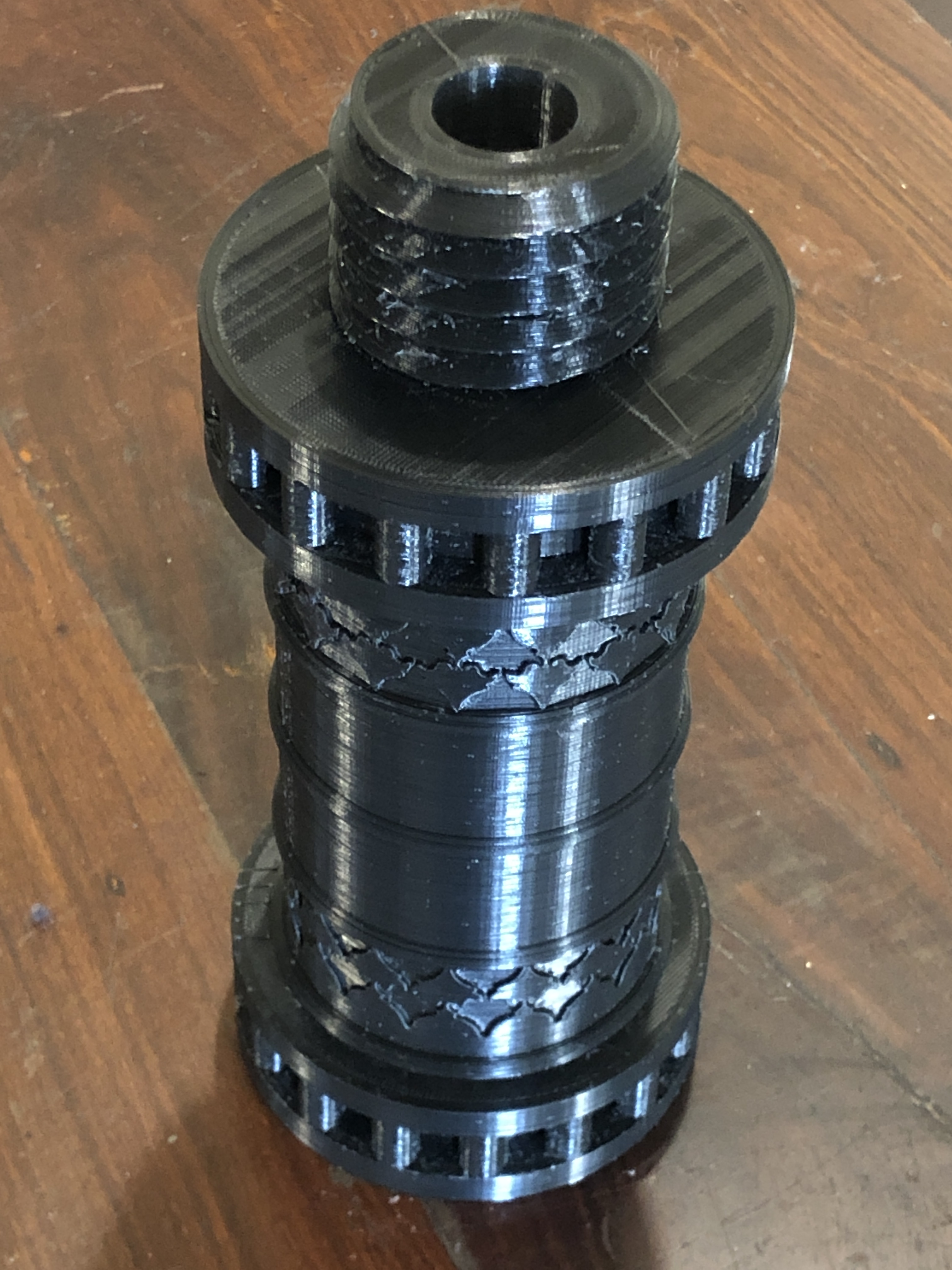
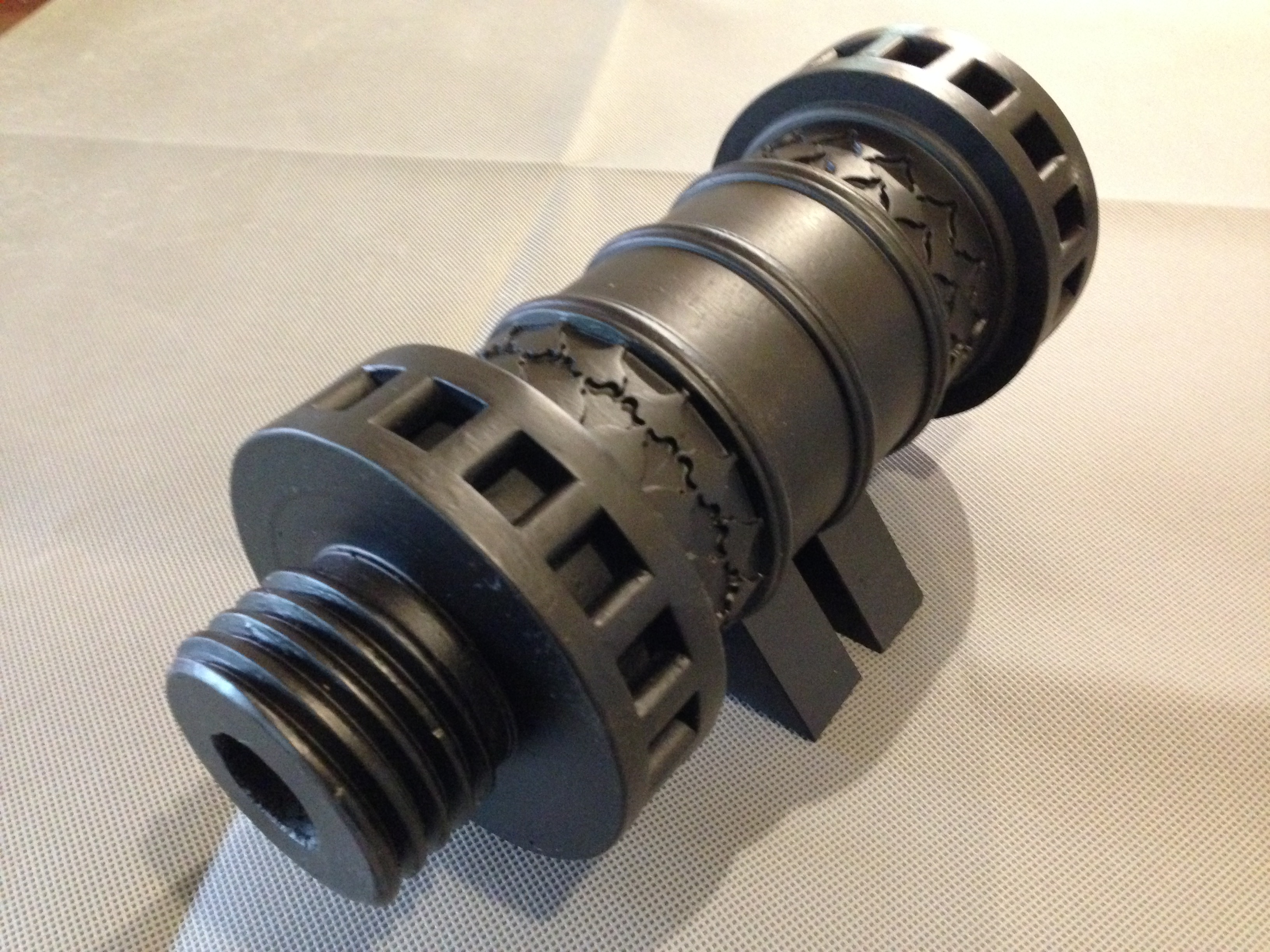
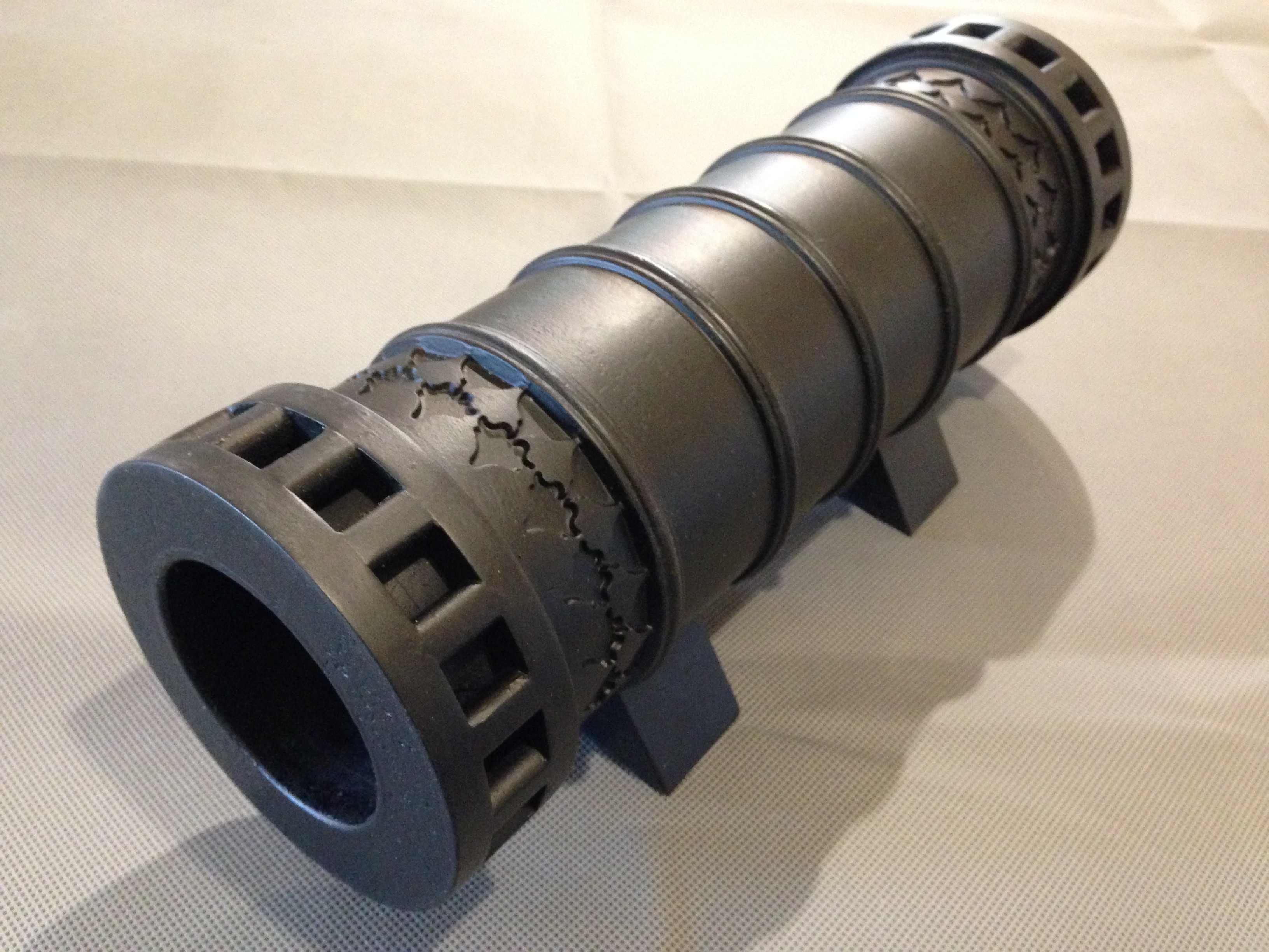
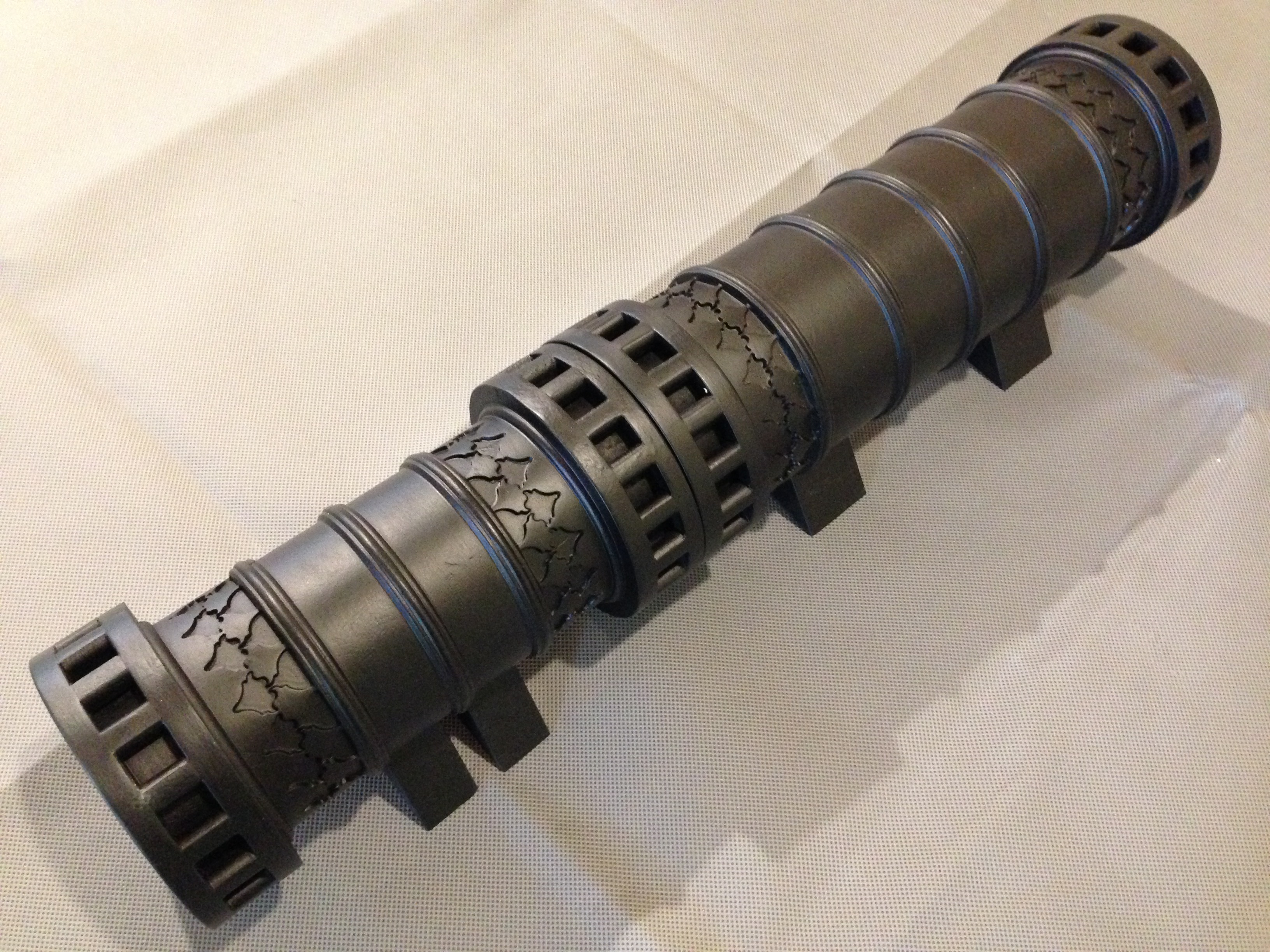
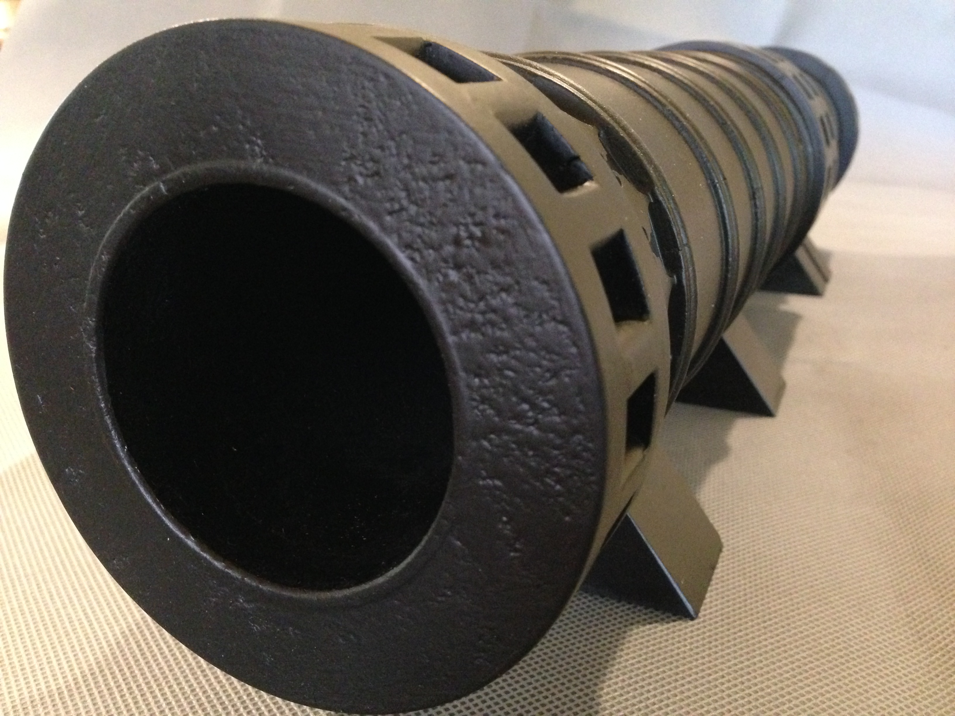
I decided that the usual rubber pouring funnel (pictured above at the bottom of the steel cylinder) would not have an adequately large bronze opening or reservoir depth, so have 3D printed one in PLA. The PLA will disappear during burnout, but will leave its shape in the investment medium and become the funnel and reservoir.
I wont be using the rubber cap/funnel mold. I hope that the 3D printed one works. Despite appearances the thin flat base is watertight. As shown here the funnel is positioned as it will be when the investment medium is poured. The cone seen is not a funnel. It is a distributor for the molten bronze. When the bronze is poured the cone will be point up.
Hard to get your head around that one? It certainly was for me when designing it.
You (and I) need to remember that any space around the PLA will become investment medium. The PLA will disappear and become a void which will be filled with bronze.
This screen shot of the 3D diagram might help. This is the pouring reservoir in the pouring position. The wide disk at top is to position the print on the steel flask. The skinny cylinders are vents to release air during the bronze pour. The stepped cylinder in the middle sits on the inside lip of the barrel. The inverted cone will be solid investment to direct the bronze into the barrel void. Confused? Maybe this will help. This is the position the PLA parts will sit inside the steel cylinder during the pour of the investment medium and later during the PLA melt/burnout.During the bronze pour the PLA components will be voids, which the bronze will fill. (except for the widest disk at the top which will disappear.)
The 3D print took over 8 hours. 0.2mm layers, 210ºc extruder temperature, 3000mm/min. I will need to do a similar 3D print for the breech. If either or both pours fail the whole process will need to be repeated.
Still in lockdown. Cannot visit my workshop due to the 5km travel limit. So 3D designing and printing at home is fairly good use of my time.
A few more small jobs out of the way, and some underway.
I showed you the “large” Kant Twist clamps recently.
Now I have finished the small ones. Same pattern, just reduced by 1/3. And a different handle.
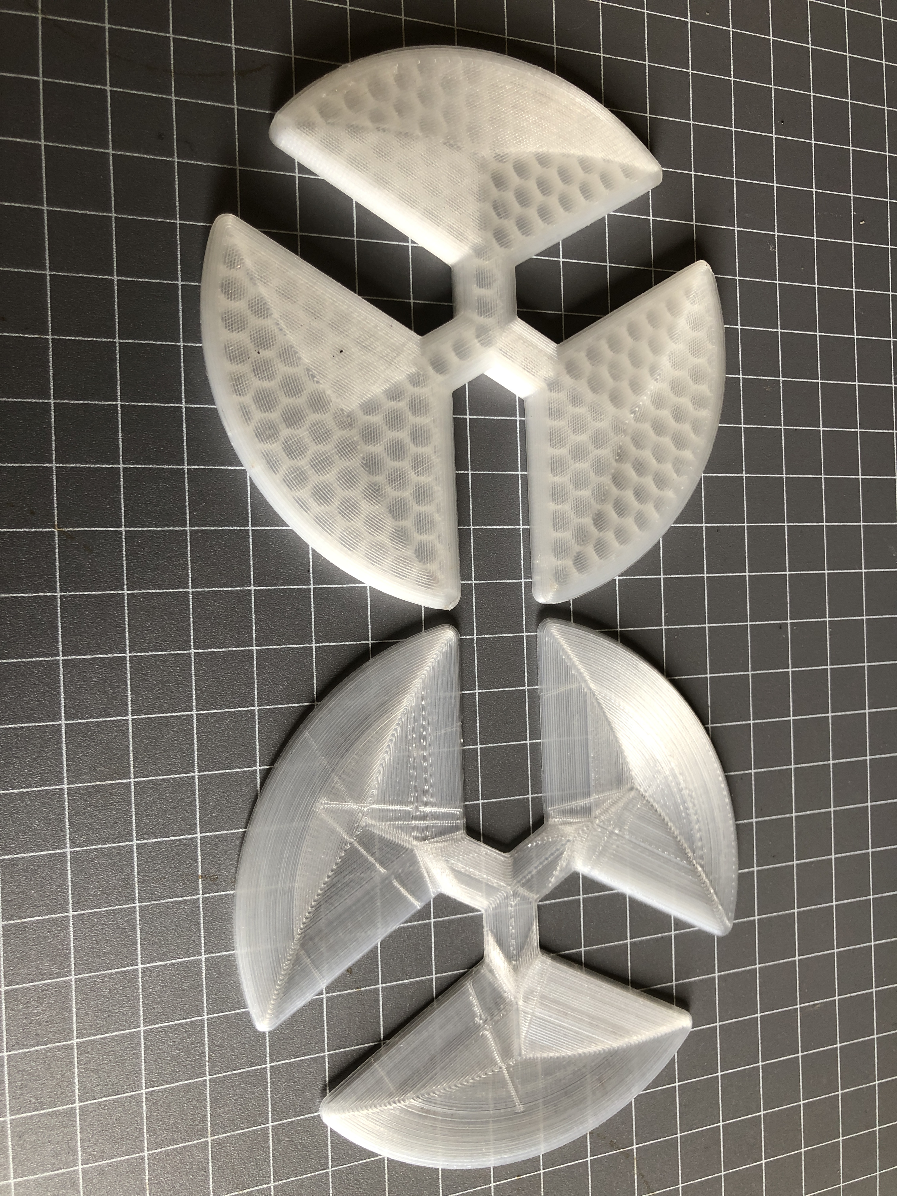
Brass pins again. Machine cut knurl was simple with a CNC rotary table. No grooves machined into the jaws. They can be done later if required.Lathe chuck spiders are not new. I have made them from steel in the past, but I never seem to have the correct thickness. Fellow GSMEE member John Bernoth brought 3D printed versions to the last meeting, and it seemed like a great idea, so I have been printing up some too. The chuck has 20mm deep jaws, so I have printed 10, 5, 2.5 and 1.5mm thick examples. I discovered that levelling the printer bed is absolutely critical to getting consistent thicknesses. Best so far is the one at bottom which is within 0.02mm. The top one was an early one, and is only within 0.1mm, so will be redone. Notice the honeycomb infill. It has 10 surface layers top, bottom and edges, plus the infill. PLA. Quite strong, but very light. Seems a good application of 3D printing technology.
And back to the bombard. (The rib pain is easing). A 14kg crucible is on the way from UK. And I have the PLA models for the mold. I do hope that I do not need to reprint them.
The 350mm SS cylinder which will hold the PLA model and the investment medium, and eventually receive the bronze. The red barrel 315 x 107mm, and the black breech 240 x 107mm. There is almost the same weight of bronze in the barrel as the breech. The breech wall is much thicker, despite the smaller OD.
Now I am thinking about how to funnel the bronze into the mold, and where to place some air vents. Also have to work out how to drain the melted PLA during burnout cycle.
Will need to make some tongs for the new big crucible.
And for my non Australian readers, we in Victoria and NSW are in Covid lockdown again. So I have plenty of time for planning for the bronze pour.
I have been attempting to print a 1:10 scale barrel of the Ottoman bombard, in PLA, so I can make a cast in jeweller’s investment, and use that to pour a bronze version of the cannon.
I borrowed a big furnace to melt the bronze, and broke 2 ribs unloading it from my vehicle. That was about a month ago. They still ache a bit, but apart from careful positioning in bed, are steadily mending. I have to sleep on my back, which would normally make my snoring unbearable, but the CPAP machine is working quite well. SWMBO absolutely insists that it is in constant use.
And I have purchased a length of 5″ stainless steel pipe to make the mold.
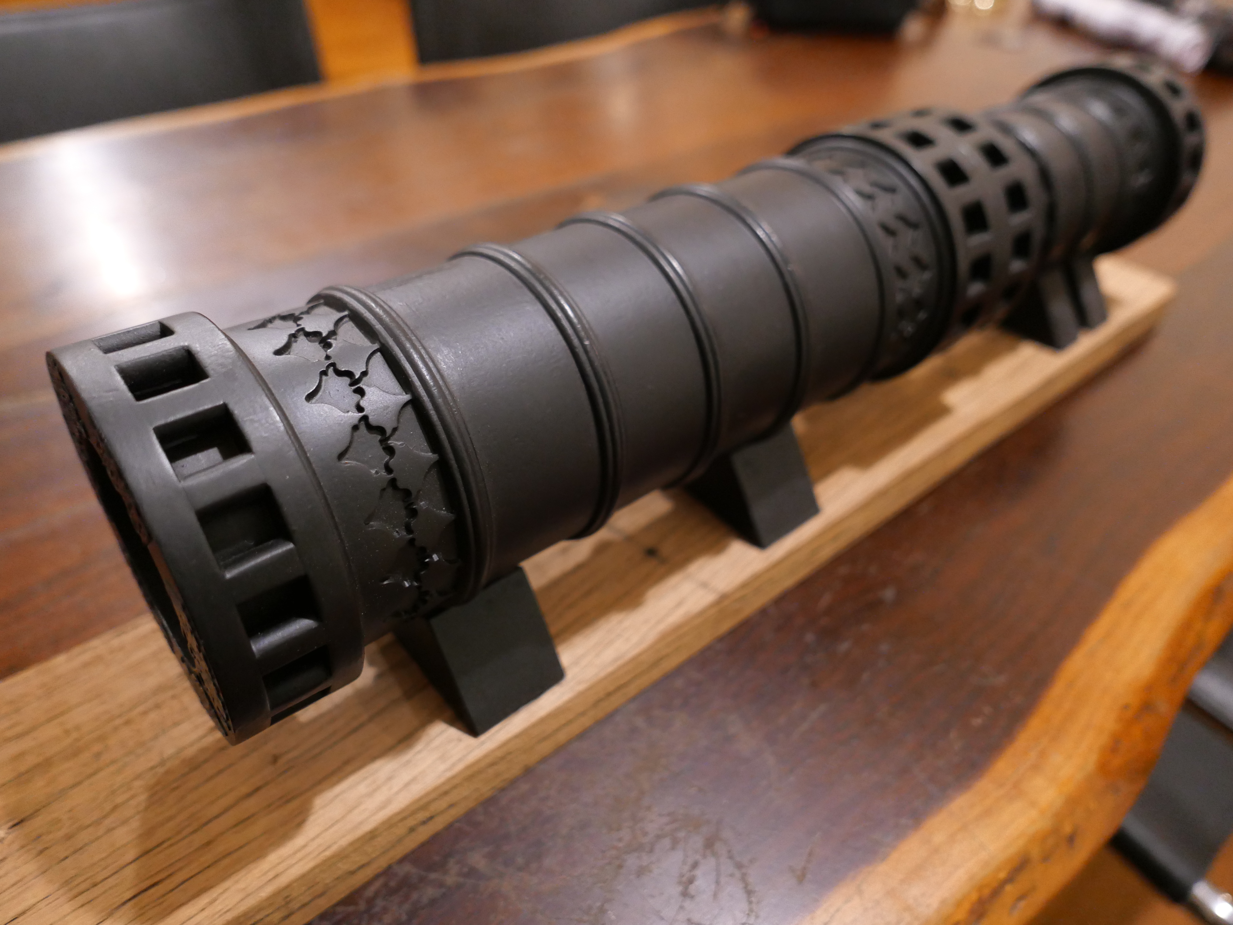
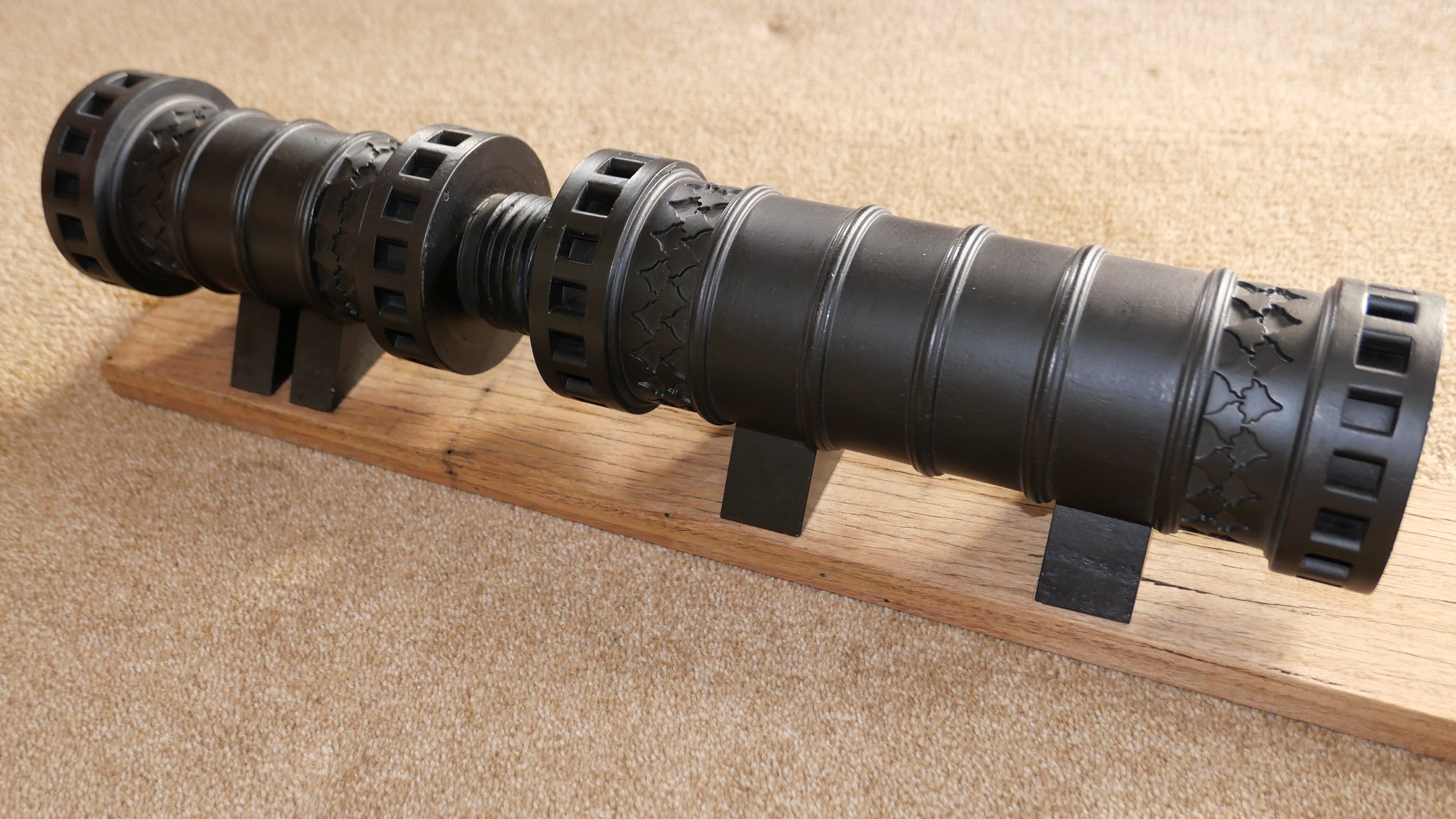
I have featured the Ottoman bombard in previous posts, having made a wooden version some years ago. It is over 500mm long, and 107mm diameter. In 2 pieces with a big thread joining the pieces.
Just to remind you of the appearance of the bombard. This is the wooden version. 500+mm long, 60mm bore.
I can’t really justify a bronze version. It will weigh close to 20kg. But it is a challenge. And I think that it will look more authentic in unpainted bronze.
I printed the breech part a few months ago.
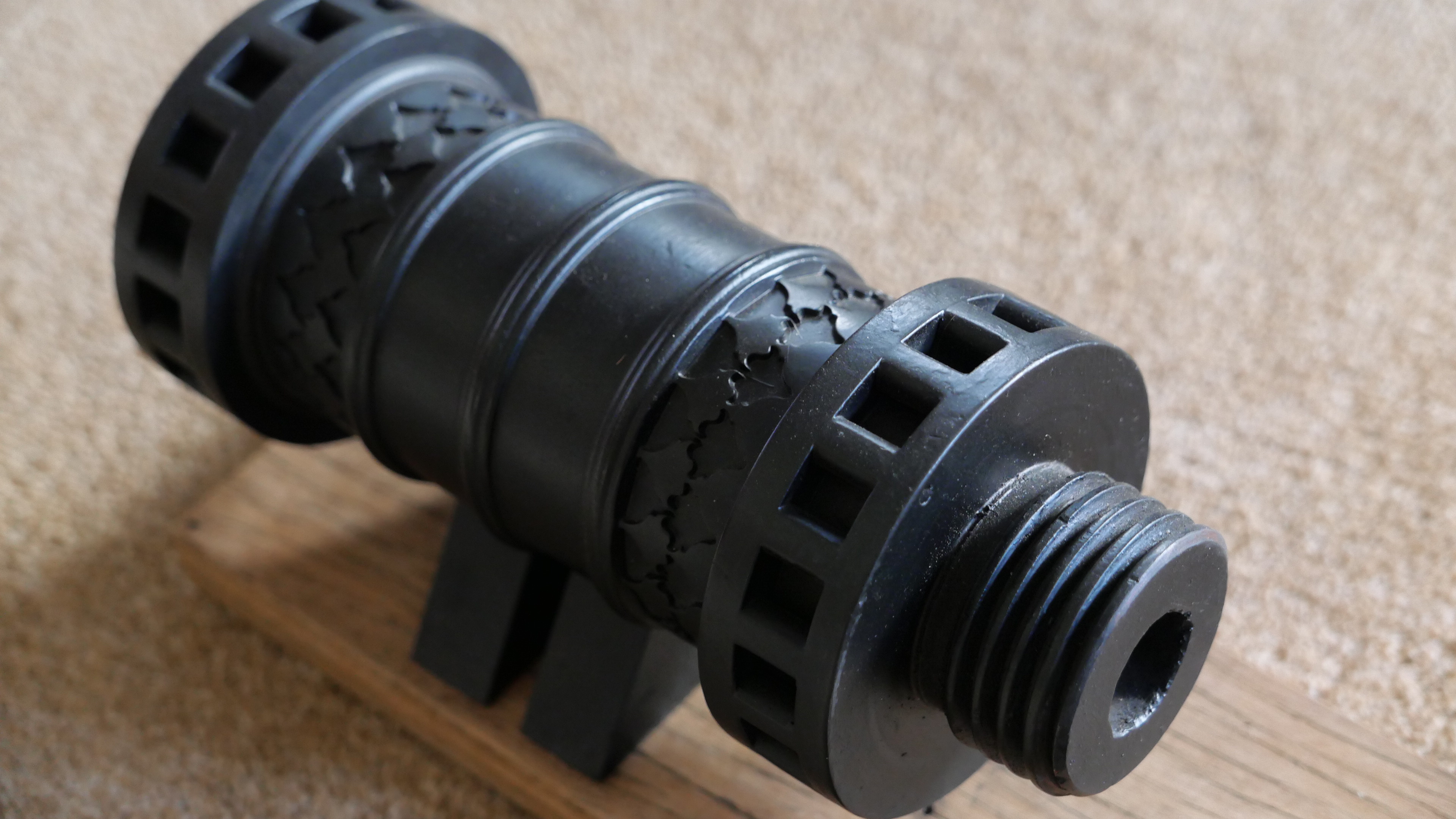
It is 240mm long, and with some post printing finishing will come up fairly well. The thread will be replaced by a redesigned thread. The original male thread on the Royal Armories bombard was tapered, so I have printed a tapered PLA version and will cut off the thread pictured above and glue on the new one before casting. I have tested the tapered thread in a test piece of printed barrel with female thread (which is not tapered) and it does go on much more easily than the parallel version, so that gun maker (Orban, the Hungarian or German) knew a thing or two.
3D PRINTING THE BARREL.
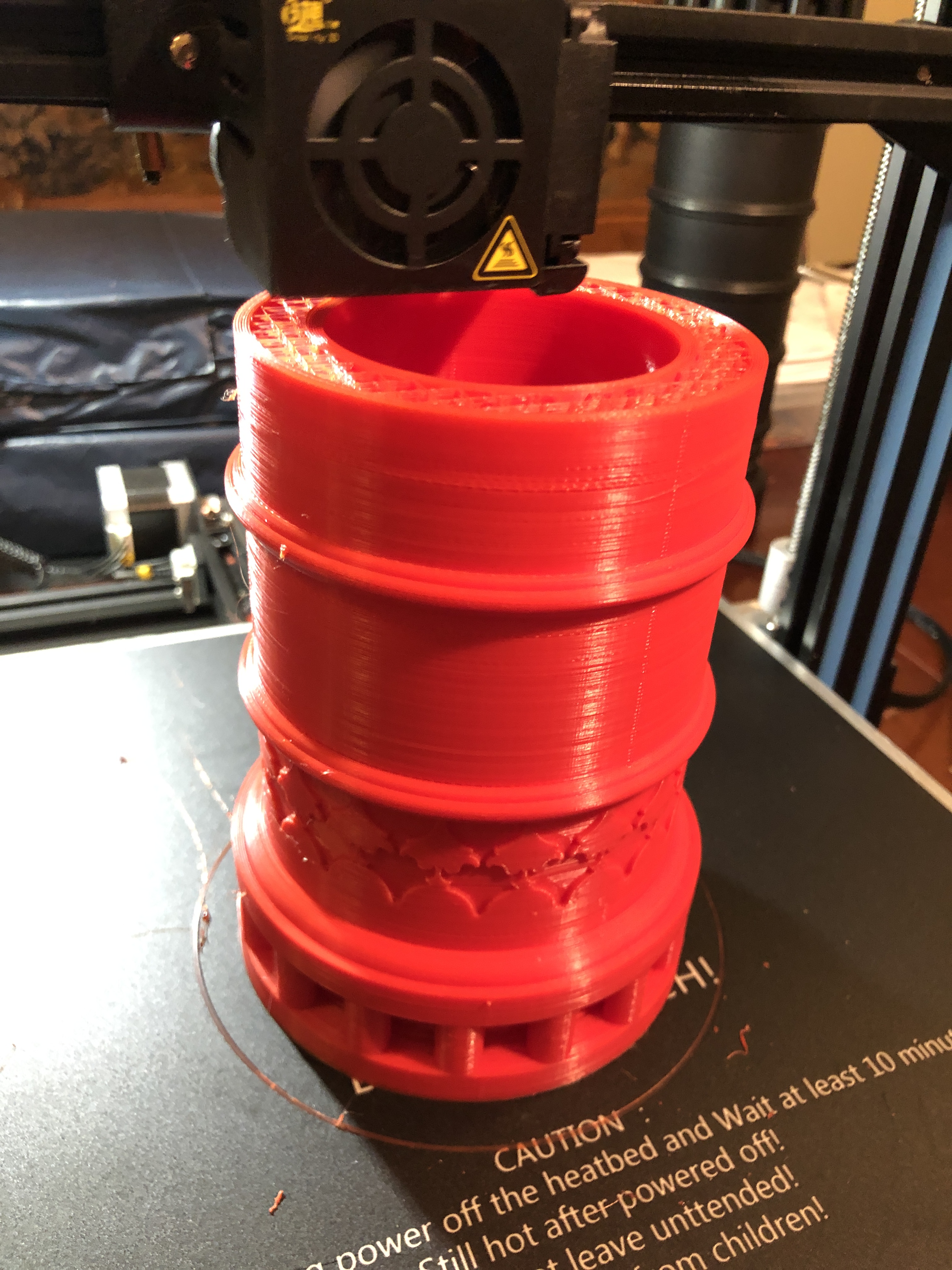
The barrel is 315mm long. My printer has a maximum print size of 300x300x400 mm so I was not anticipating any problems. I knew from the slicer program that it would take 2/3 of a 1kg reel of PLA, so I bought some new transparent PLA, thinking that it might melt/vapourise more completely in the burn out cycle of the production than the coloured PLA.
So I tried to print it. I have lost count of the number of unsuccessful attempts. Each time the print would start well, but at some point, sometimes after a whole day or 2 of printing, the print would come loose from the printer base and I would have clean up the mess of PLA spaghetti, and start again. I cleaned the printer base thoroughly. Scraped it. Wiped with acetone. Re-levelled it multiple times. But every time the print would break free.
I also noticed that I was getting a lot of stringing, and lumps of PLA would form on the printed surface, cool and harden, and sometimes the print nozzle would hit the hard lumps. That is when the print would loosen from the base and eventually break free.
I have been using a 3M printing cover over the aluminium printer base, quite successfully for over a year. Maybe the cover had worn out. I looked up the P.I. for the cover, and yes, it has a stated expected life of 10 uses! So that was likely the cause of the adherence problem because I must have used that cover at least 50 times!
I had no replacement 3M cover, so I reverted to the original cover supplied with the machine, which was boro-silicate glass. Initially it worked well, with good print adherence, but the hard lumps were still forming, and when the nozzle hit them, there was enough force to break the glass plate free.
What could be causing the hard lumps?
I watched multiple YouTube videos. Re-levelled the bed again. Checked every nut and bolt on the printer for tightness with no problem found. Checked the Z axis for level.
By this stage I was contemplating buying a new printer. Maybe one of those liquid + UV light jobs. But one of those big enough to make my barrel would cost thousands. So I got a quote from a professional printing service to print the barrel…. almost $AUD600. I would have done that, but the print is destroyed in the making of the cast, and it is possible that more than one attempt of bronze casting will be required. I was considering abandoning the entire project.
One last try at a print. I replaced the 3M cover with a new cover, and started a new print with a new reel of red PLA.
All seemed to be going well.
The print was adhering solidly to the new 3m cover. The hard lumps were still appearing, but the print head ploughed through them or knocked them off completely. The problem was, that after 3 days of printing, with 10% of the barrel still to go, the multiple jarrings were producing axis shifts. The appearance was pretty bad, but I figured that I could fix it with some extensive post printing hand finishing.
By this stage the print was almost 300mm high, and I could watch the laying of the PLA extrusion from the print head directly. In retrospect I should have used a mirror to do this at a much earlier stage.
What I saw explained the issue of the hard lumps appearing.
PLA was slowly oozing from around the base of the extruder nozzle. It was gradually building up into a pea size lump, and eventually falling off onto the print face!
So, I paused the print, picked off the accumulating lump, and watched some more. The same thing happened.
Why was the base of the nozzle leaking? Another pause. Checked the tightness of the nozzle. It was totally loose. About a full turn!
Tightened it up. Resumed printing.
The next layer did not adhere at all to the previous one, because tightening the nozzle had lifted it at least one mm.
The almost completely printed barrel. Lots of stringing. No hard lumps in this picture. This is in the dining room of my house. The room has been unused since the start of Covid. Quite handy and warm for printing.
I thought that I could start a new print of the final 10% of the barrel, and glue it to the part pictured, but when I examined it, the layers were poorly adherent, and falling apart. It went into the plastics bin. I expect that the loose nozzle caused multiple print faults in x, y, and z axes.
A record of printing failures.
So, I am now 32 hours into the next attempt, with 47% completed.
See the difference? No stringing. No lumps. Quite a reasonable surface. Fingers crossed.
Almost finished the model Armstrong 80pr RML, and just starting another project. I have mentioned it in previous posts…. a 1:10 scale model of the 17 ton Turkish bombard, which currently resides at the Royal Armories Museum, Fort Nelson, Portsmouth, UK.
The original was in 2 pieces, to make the casting process manageable, and presumably to make transporting the monster cannon more manageable. The museum states that another reason for the screw thread join of the 2 massive parts was to separate the halves for reloading, but I can find no substantiating references for that statement. And it does not make sense to my conception of what would have been involved in the reloading process.
At 1:10 scale the model will be over 500mm long, and will presumably weigh approximately 17kg (37.5lb). Each piece will weigh 8-9kg. I will make the model in 2 pieces, for authenticity, and to make the casting more manageable, and to make the 3D printing possible. My 3D printer has a maximum model size of 300x300x400mm.
I spent several days drawing up the breech and saving it as an stl file, for the slicer (Simplify 3D) to process. The slicer predicted that the print would take 51 hours, and consume 697g (1.5lb) of PLA. I used 0.2mm layers, with 8 top, 8 bottom, and 6 side layers, and 10% fill, and since there wee some 90º overhangs, I decided to add supports.
And guess what. The print took 51 hours, and consumed most of a 1kg roll of PLA.
I chose to operate the extruder a bit hotter than normal, at 225ºc, and heated the platen to 65ºc. I wanted to make sure that this print was water tight for the moulding process, and remained adherent to the platen for the duration of the print. I accepted that the detail of the print surface would be a little coarser than could be achieved at a finer layer thickness, but the benefit would be increased water tightness.
The Ottoman Bombard at Fort Nelson. In the background is the barrel for the supergun which Saddam Hussein ordered, but was prevented from being exported from the UK.After about a day of printing. On our dining room table (which I made many years ago).Phew! Printing completed.Most of what can be seen here are the supports.It took about an hour to remove the supports. They were particularly resistant to remove from behind the pins.I will spend a few more hours sanding and filing and filling the surfaces, before making the molds with the investment powder.
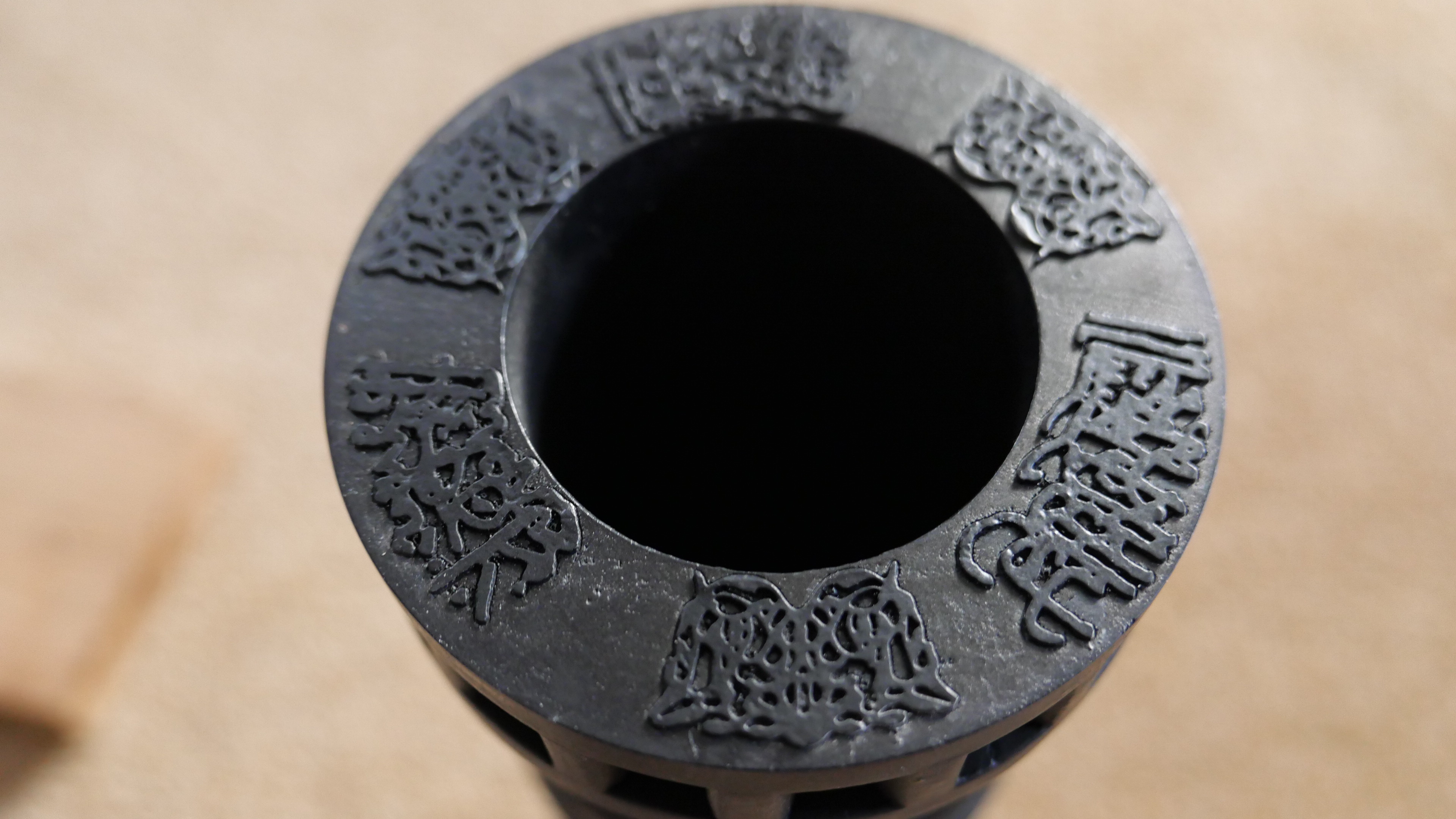
I am still drawing up the barrel. Well, actually, it is fully drawn up, but I am refining the drawing of the Arabic script which is embossed on the muzzle. It is quite difficult to convert the squiggles and patterns to vectors, which can be used to produce the STL file for the 3D printer.
The Arabic patterns and script on the muzzle. At 12, 4 and 8 are floral patterns. The calligraphy reads “Help O Allah. The Sultan Mohammed Khan son of Murad. The work of Kamina Ali in the month of Rejeb. In the year 868″. (CE. 1464). p.s. I did not previously notice the alien watching me , top right.
Some more photos with the Panasonic Lumix LX100M2.
The Trevithick dredger engine, still lacking lagging and paint. The chimney has a chimney extension connector, sitting a bit crooked.
I am very impressed by the quality of these photos.
And some shots of the 1:10 model Ottoman Dardanelles cannon, which I made a few years ago. It was intended as a practice run in wood, before making it in bronze. The wooden model is 600mm (2′) long, and since finishing it I have not felt the need to make a bronze example. I plan to visit the original at Fort Nelson, Portsmouth, in a few weeks. Watch out for a video/photographs on johnsmachines.com
I think that you will agree that the quality of these photos is excellent. The photographer is still learning.
I would have preferred that the title of this blog was “Finishing the Ottoman Bombard”, but I am still waiting for the vectors of the barrel mouth decorations and Arabic (?) writing, and the touch hole.
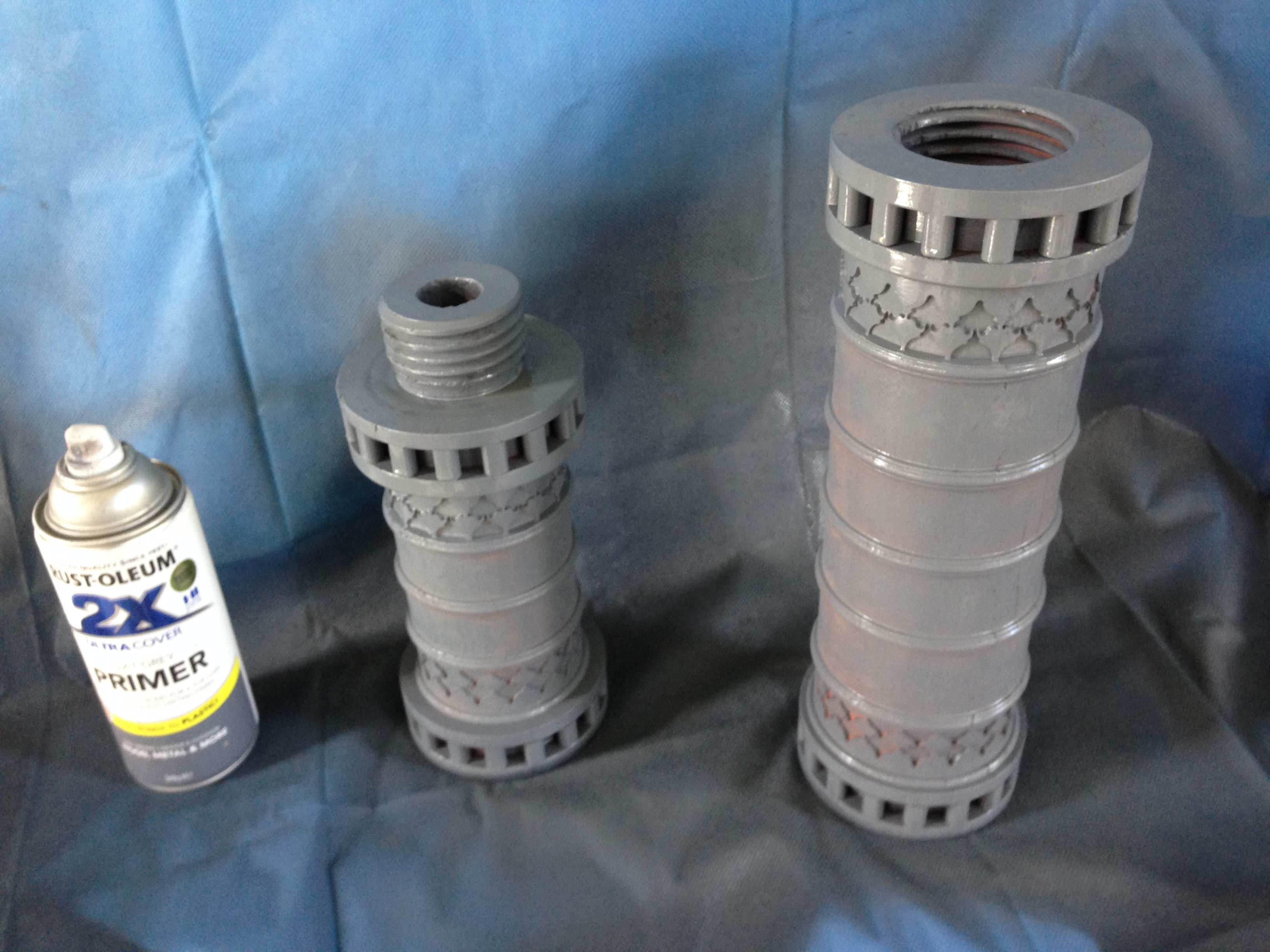
But I have at least painted the bombard, and the pictures follow. You will notice that I have not attempted to reproduce the bronze or copper colours of the orginal in Fort Nelson. Partly because I doubted my ability to make painting such variegated patterns realistic, and partly because the cannon would not have looked like that in its heyday of 1464. It would probably have been either black, like most SBML cannons (smooth bore muzzle loading), or possibly gaudy golds and reds and blues like other medieval items. So I painted it black. I like it. If I get evidence that it should be more colourful I can change it later.
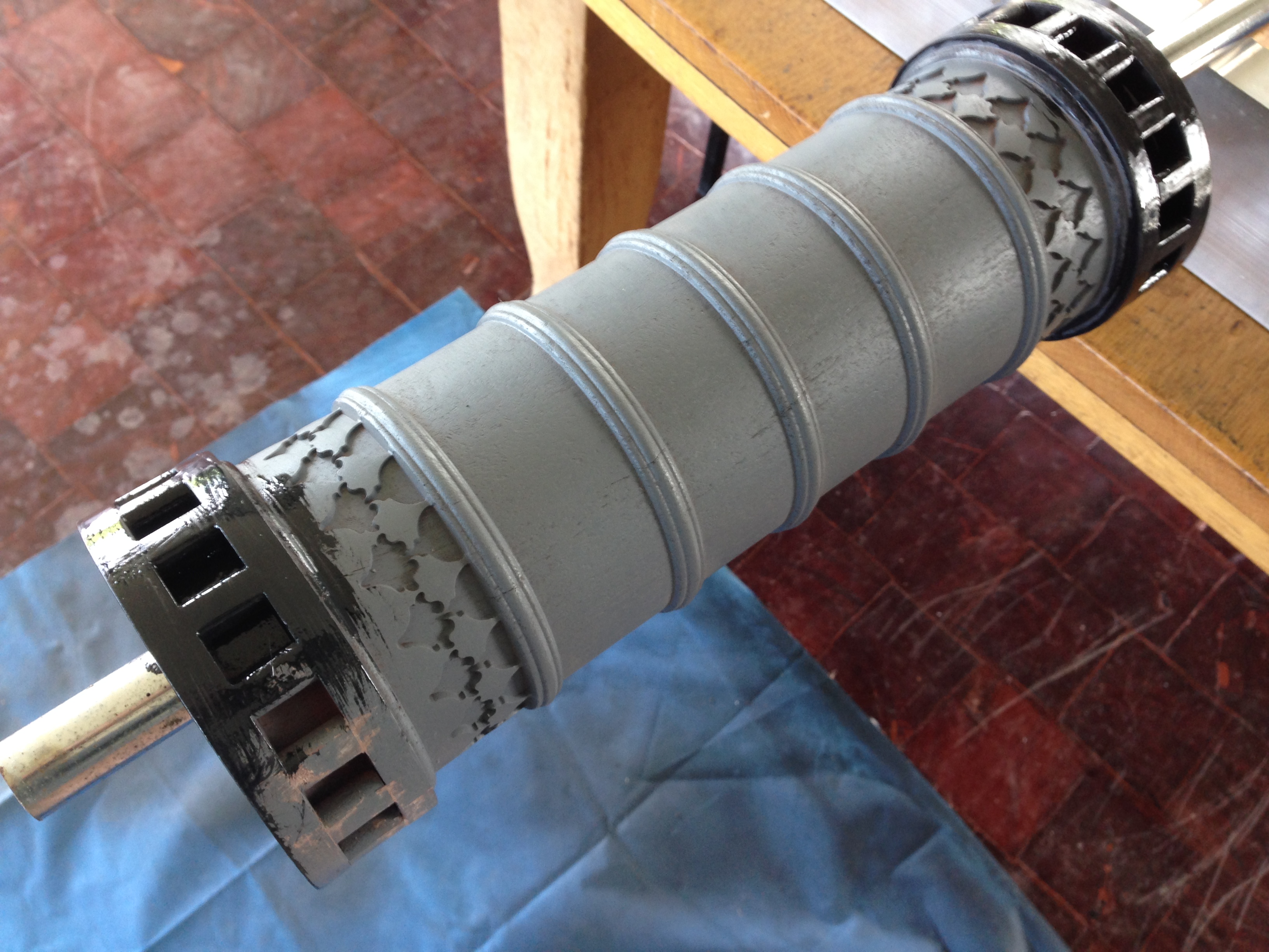
First coat – Primer. Hmmm… interesting colour.
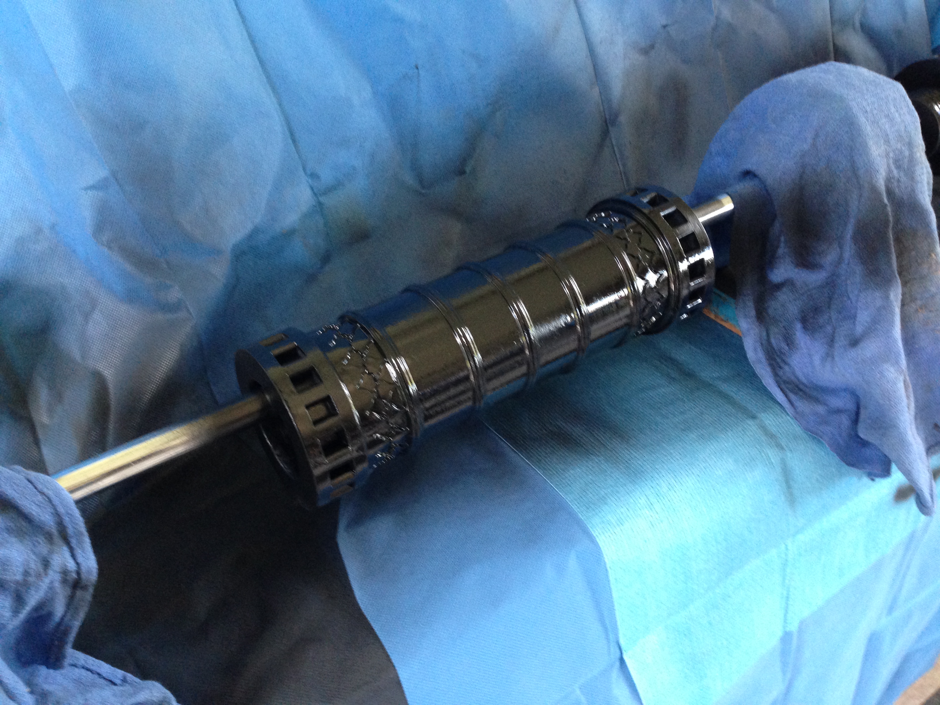
Next coat – matt black brushed on, to fill the hairline wood cracks. Incidentally, the (dirty) parquetry floor is also made from the red gum house stumps from which the cannon is made.
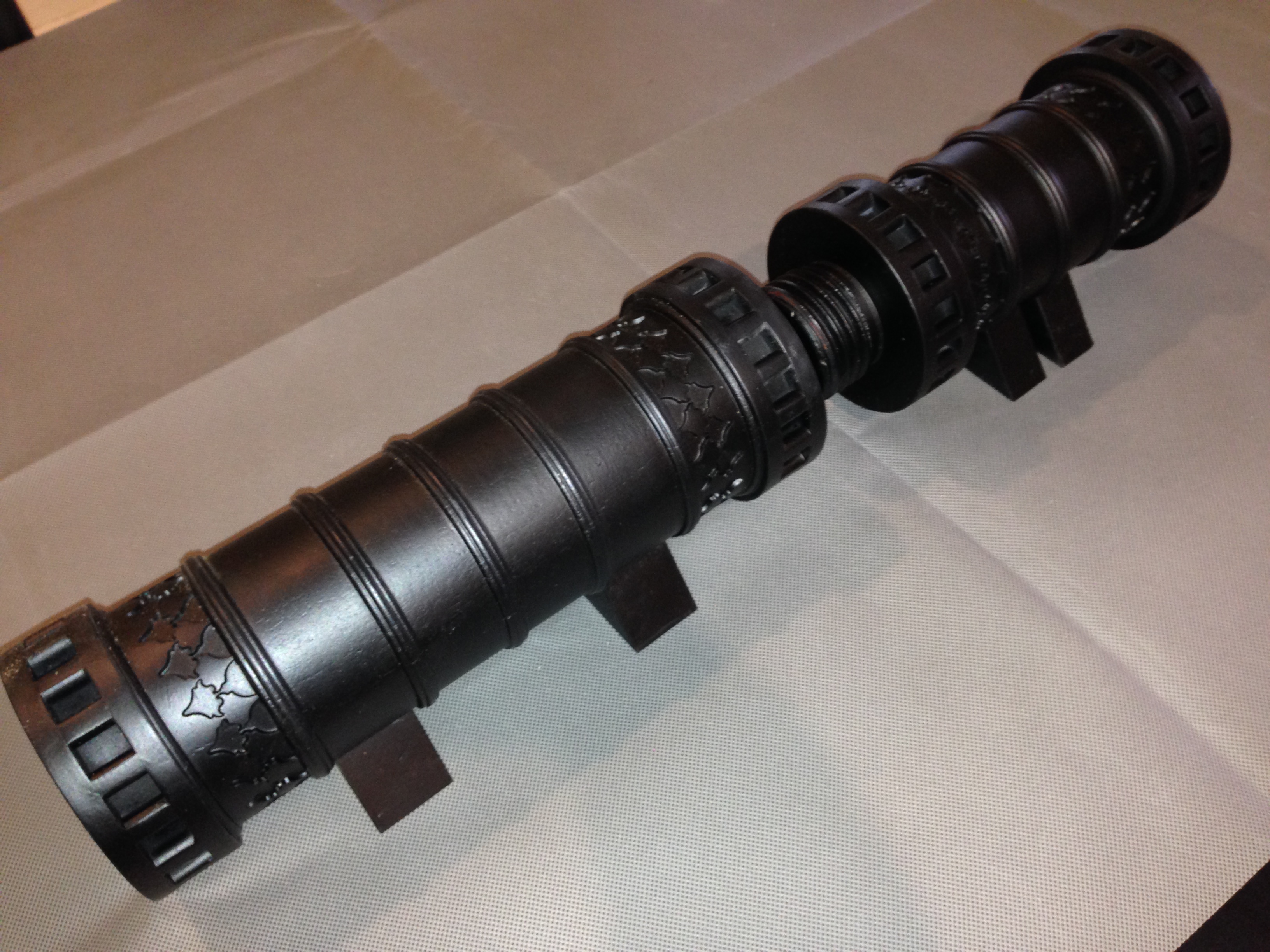
final two coats – matt black, from a spray can.
So there it is, finished except for the barrel mouth engraving, and the touch hole. Now what to do with it… SWMBO says it might be useful as an umbrella stand.
The breech. 25mm diameter explosion chamber. 1:10 scale
This is the low res photo from Fort Nelson. High res photo on its way.
In the meantime, I have contracted with a US firm to convert the picture to vectors. More $US. ($US50 to be exact).
I am not sure that this is going to work. But I will report to you.
I do wonder what that the Arabic/Turkish writing means. Does anyone know? I am pretty sure that it is not complimentary to Christians/Westerners/Non Muslims. Maybe it is just an instruction not to look before the touch hole is touched. Or “do not stand here”.
PS. Note added 17 Oct 2016. The translation is “Help O God the Sultan Mehmet Khan son of Murad. The work of Munir Ali in the month of Rejeb. In the year 868.”
Does anyone have a decent photograph of the writing on the muzzle?
I have repeatedly hunted through every picture which I can find on the net, but they are either taken at an angle, or too poor quality to be useable.
Does anyone have a photograph which I could beg buy or borrow?
I also need a photo of the touch hole.
I have contacted the Fort Nelson Armoury Museum, but not too surprisingly there was no response.
Is there someone in the Portsmouth UK area who could pop in and take some pics for me?
POSTSCRIPT: October 5. I have had 2 excellent and positive responses to my appeal.
First, reader Richard sent me a connection to a Turkish Dr/Professor, who has made a 1:25 model of the bombard using 3D printing. (at least that is how I think he has done it. My Turkish is non existent). I am following this lead.
Secondly I have had a response from Fort Nelson Armoury, with a good photo of the barrel mouth, and a high res photo on the way, after payment of a significant, but not unreasonable fee. Isn’t the Internet wonderful!!
I have found this video to be particularly useful in my modelling of the Ottoman bombard. The subject of this video is the gun that the Turkish sultan gifted to Queen Victoria when the Brits and the Turks were allies. It might be one of the guns which fired on the British fleet in 1807, when it (the gun) was 343 years old!
Notice the colour. It is aged bronze. I am thinking about how to reproduce that colour on my model.
Length of the assembled gun 5.2m (17′)
Bore 635mm
Breech weight 8942kg
Barrel weight 8128kg
Average weight of shot 307kg
the model is at a scale of 1:10. photos soon. being painted.
There are 16 pins at each end of each section of the cannon.
These were certainly used as leverage points, for very strong men with large levers to rotate the 8-9 tonne segments against each other to engage and tighten the screw.
I cannot see how the pins would have been cast with the breech and barrel. For my model I decided to make separate pins and fit them into the gap between the big rings, then insert a grub screw through both rings and the pin. The holes are then filled.
I wonder if a similar method was used in 1464. I would love to have a close look at the original cannon to figure this out. From the photographs, I can see no evidence of later insertion of pins, but neither can I see how it would have been done any other way.
Drilling the holes for the grub screws
In order to continue with red gum, I made my own pins. This is the setup. The blank is held approximately centre in a 4 jaw….
…and the pins are turned, centre drilled, drilled, cut to length, and tapped M4. 64 altogether.
The M4 x 25mm grubscrew is screwed into the pin. The wood join is super glued. Also, I am attempting to patch the worst of the thread tearouts.
Using a battery screwdriver to insert the grub screws. The pins protrude above the ring surface for a reason..
Sanding the pins flush with the rings. Check the photo of the original 1464 model. There is also some wood filler in other splits. Not surprising after holding up a house for 70 years.
The holes are now filled with wood filler, and will be sanded flush. They should be invisible after painting.
Next the painting, the stands, and some cannon balls. How to reproduce that aged copper colour…