johnsmachines

machines which I have made, am making, or intend to make, and some other stuff. If you find this site interesting, please leave a comment. I read every comment and respond to most. n.b. There is a list of my first 800 posts in my post of 17 June 2021, titled "800 Posts"

Tag: silver soldering

Silver Soldering. Another Method of Parts Positioning.

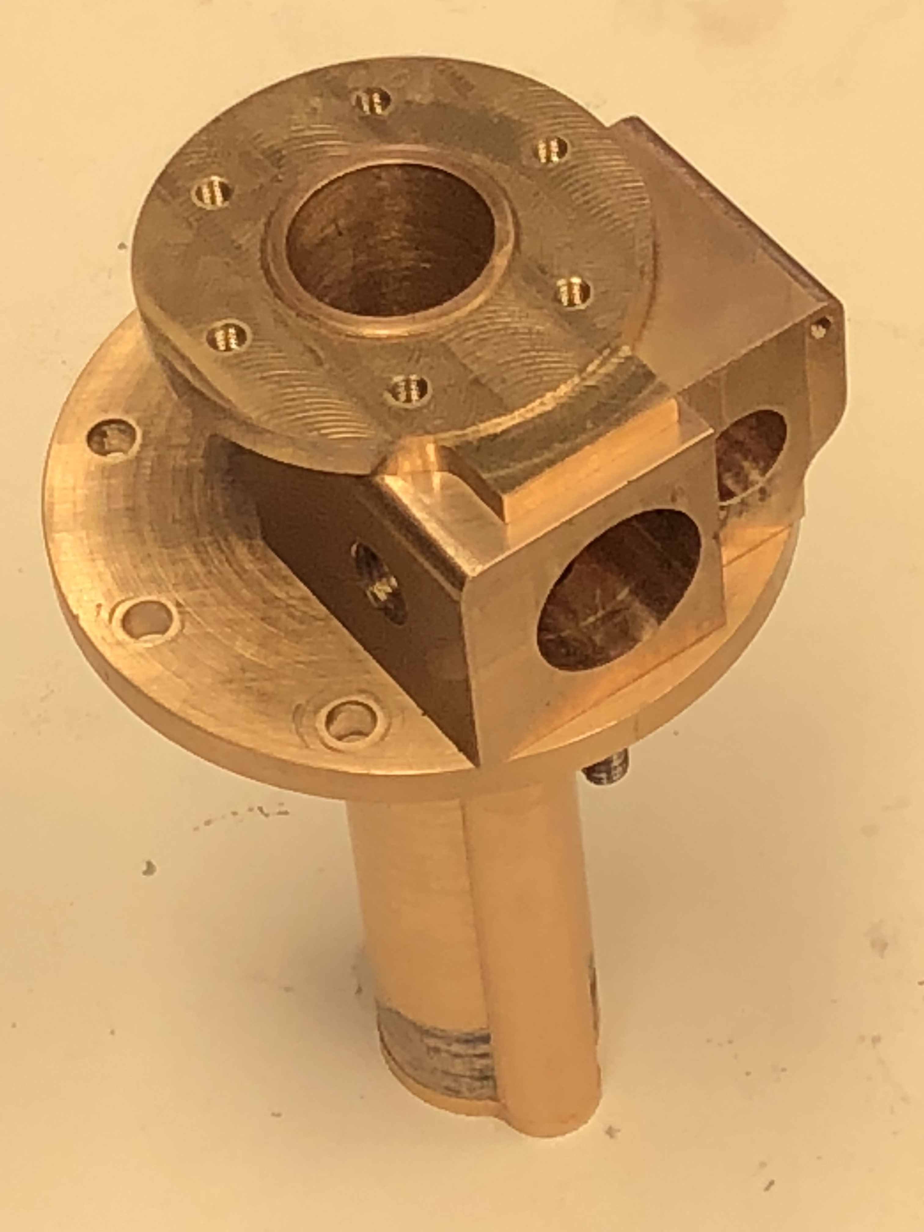
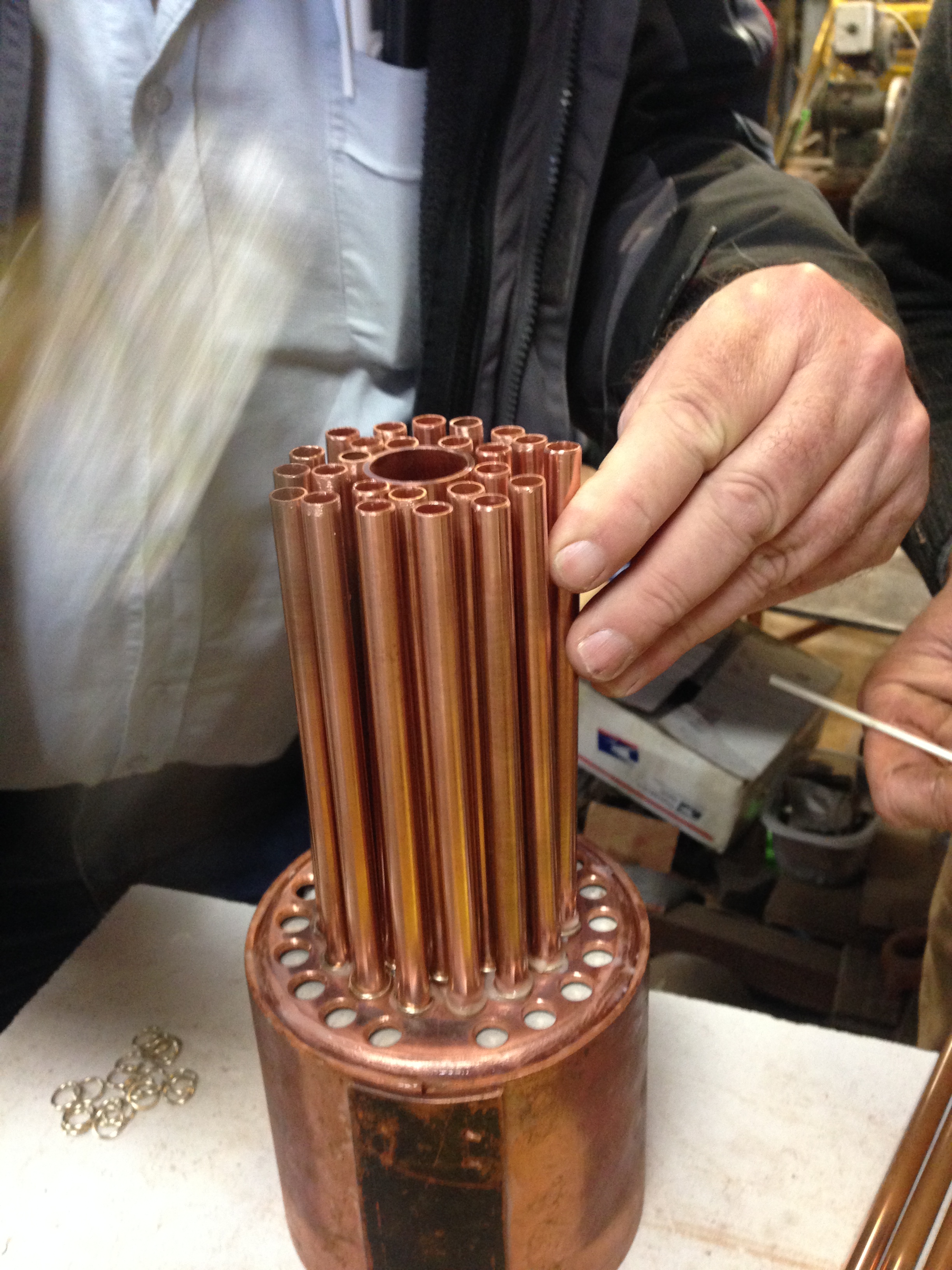
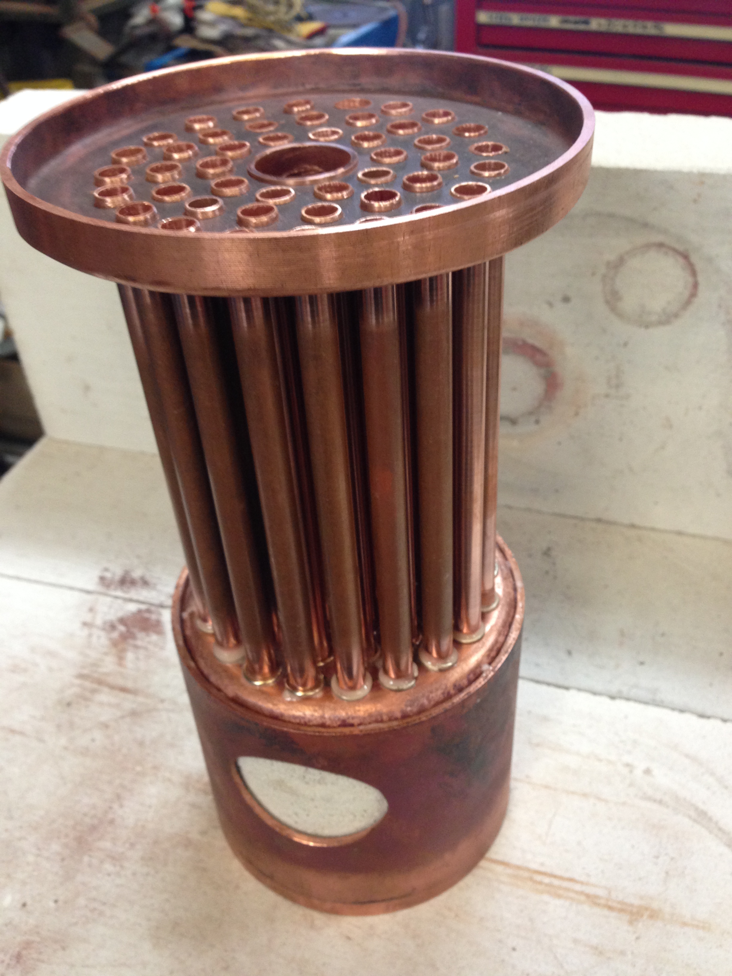
This is one of the few parts required to finish the model Armstrong 80pr RML cannon on a wooden carriage and traversing platform.

It is the ring which is attached to the rear of the carriage, used to control the descent of the carriage and barrel down the slide to the firing position, with a rope attached to the ring. The bracket is buried within the rear transom, and extends underneath the transom with more screws and bolts.
I cut the bracket pieces from 2mm flat brass strip, using a 3mm diameter endmill.

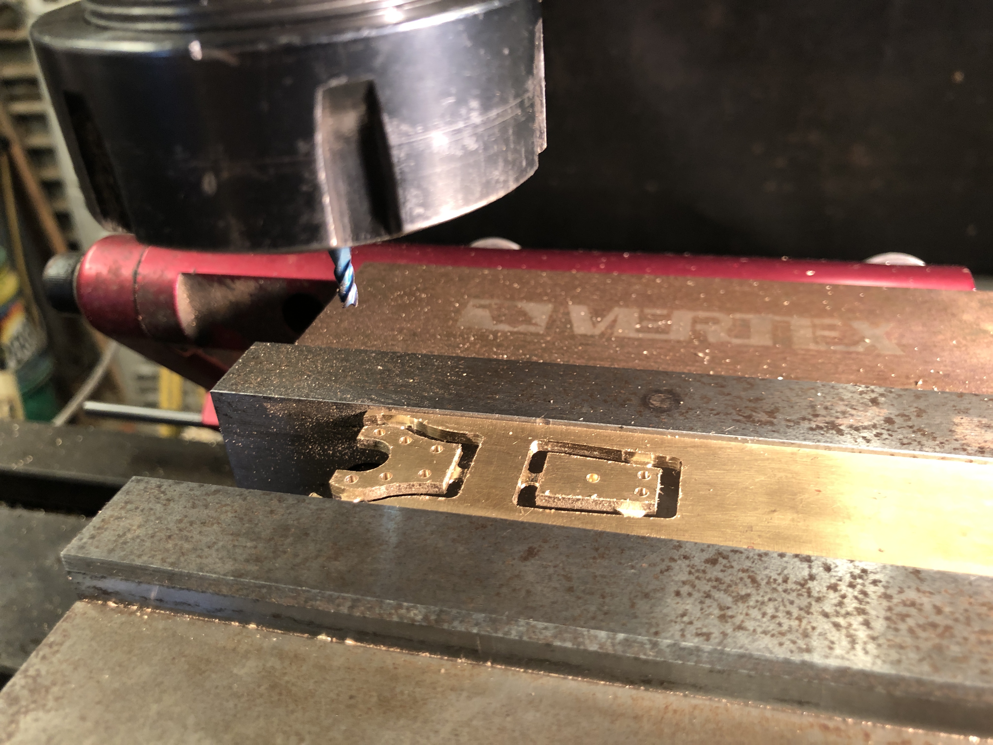
The issue in silver soldering the pieces together was that they are quite small, about the size of my little fingernail, joined at an 95º angle, with the ring also soldered in place in the same heating session. And I did not want solder getting into those 1.6mm diameter holes.

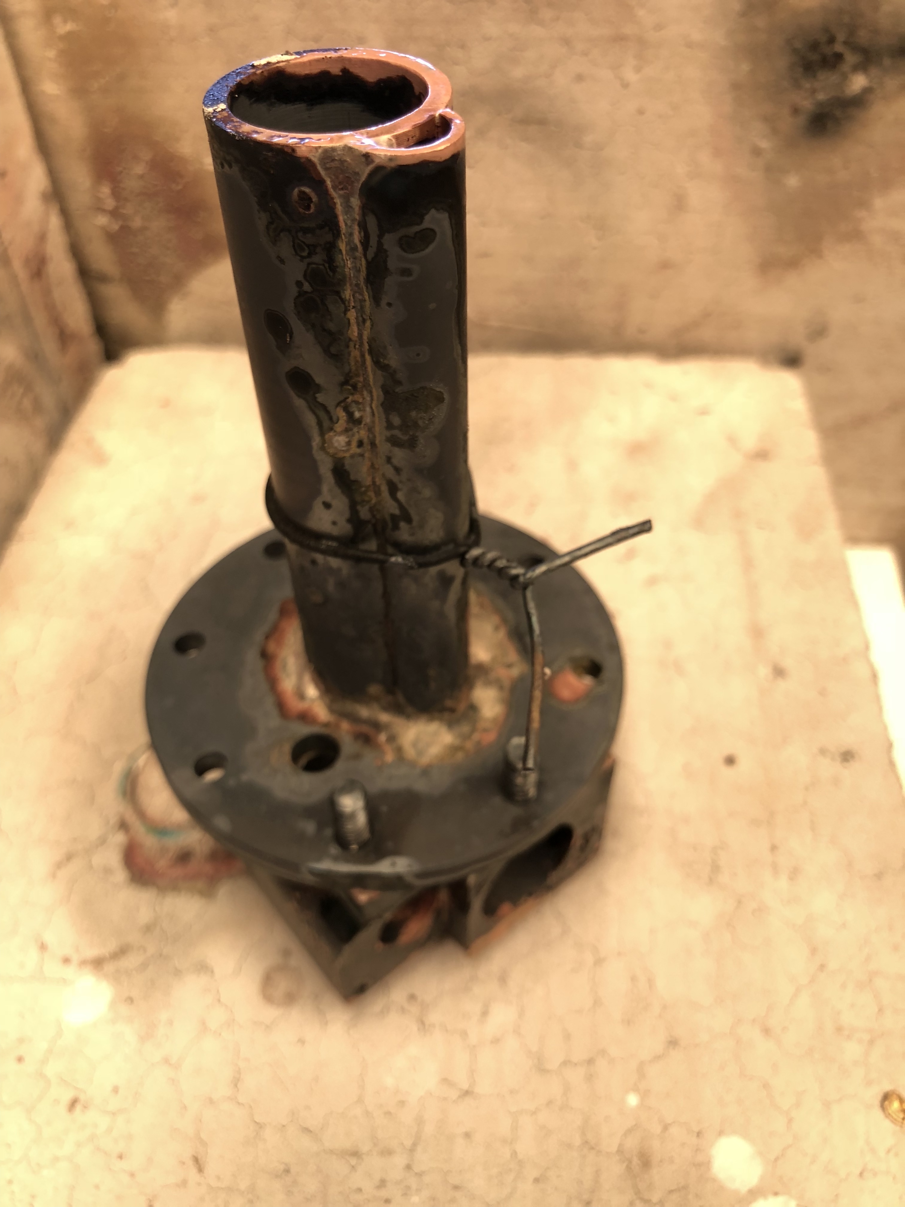
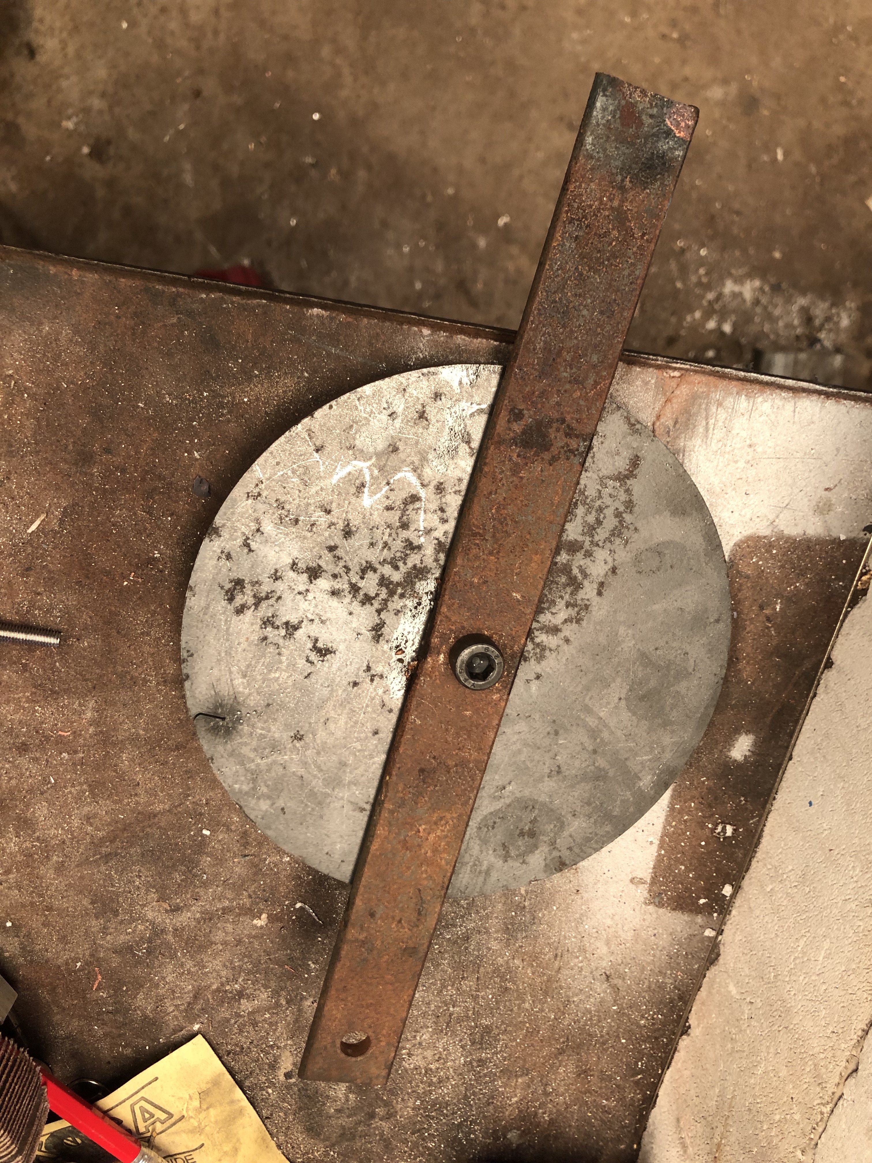
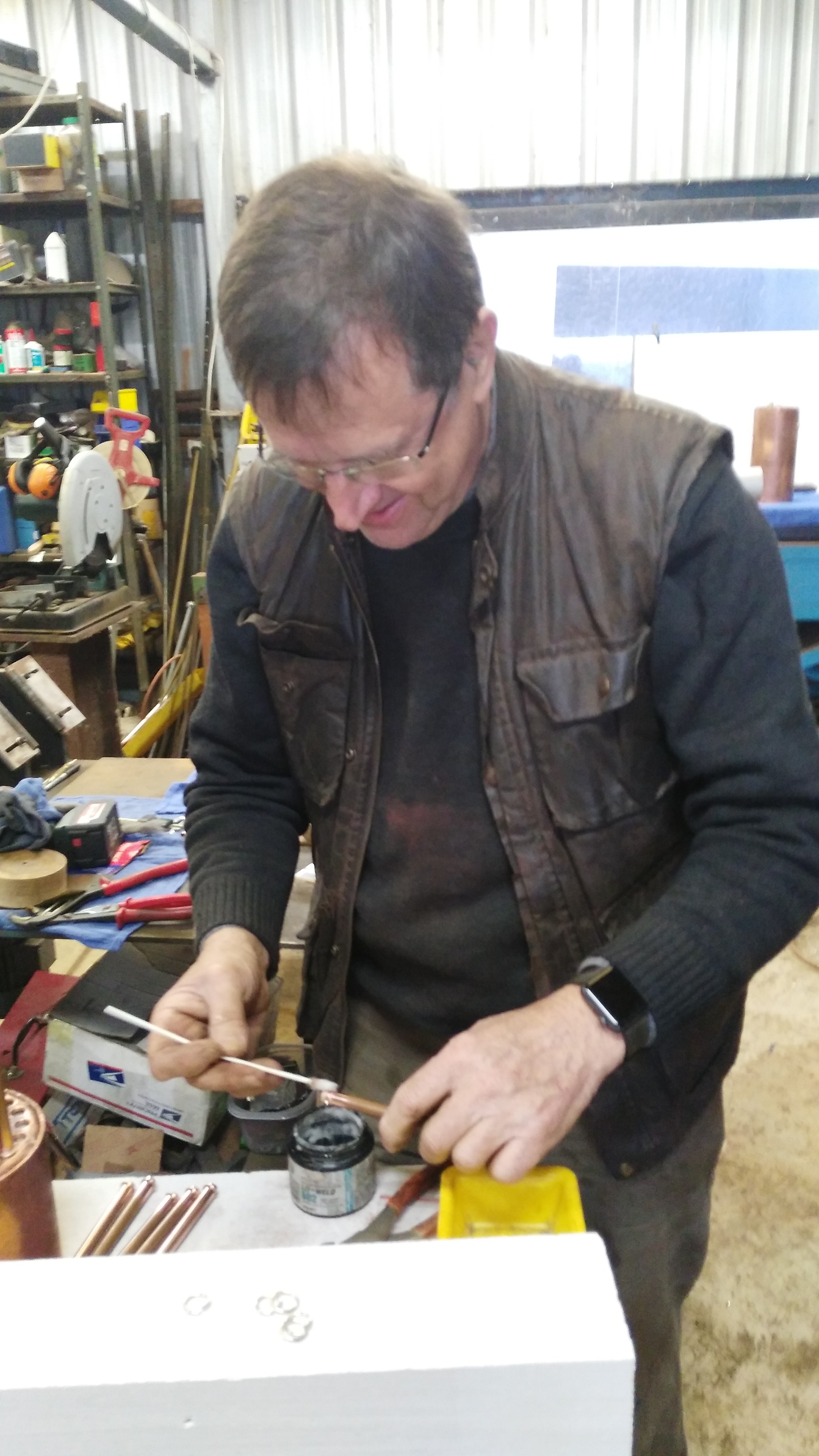
So I screwed the angle pieces to a block of hardwood which had a 95º angle, having fluxed the edges carefully to exclude the flux from the tiny holes. I would have added typists white-out if I could have found it.

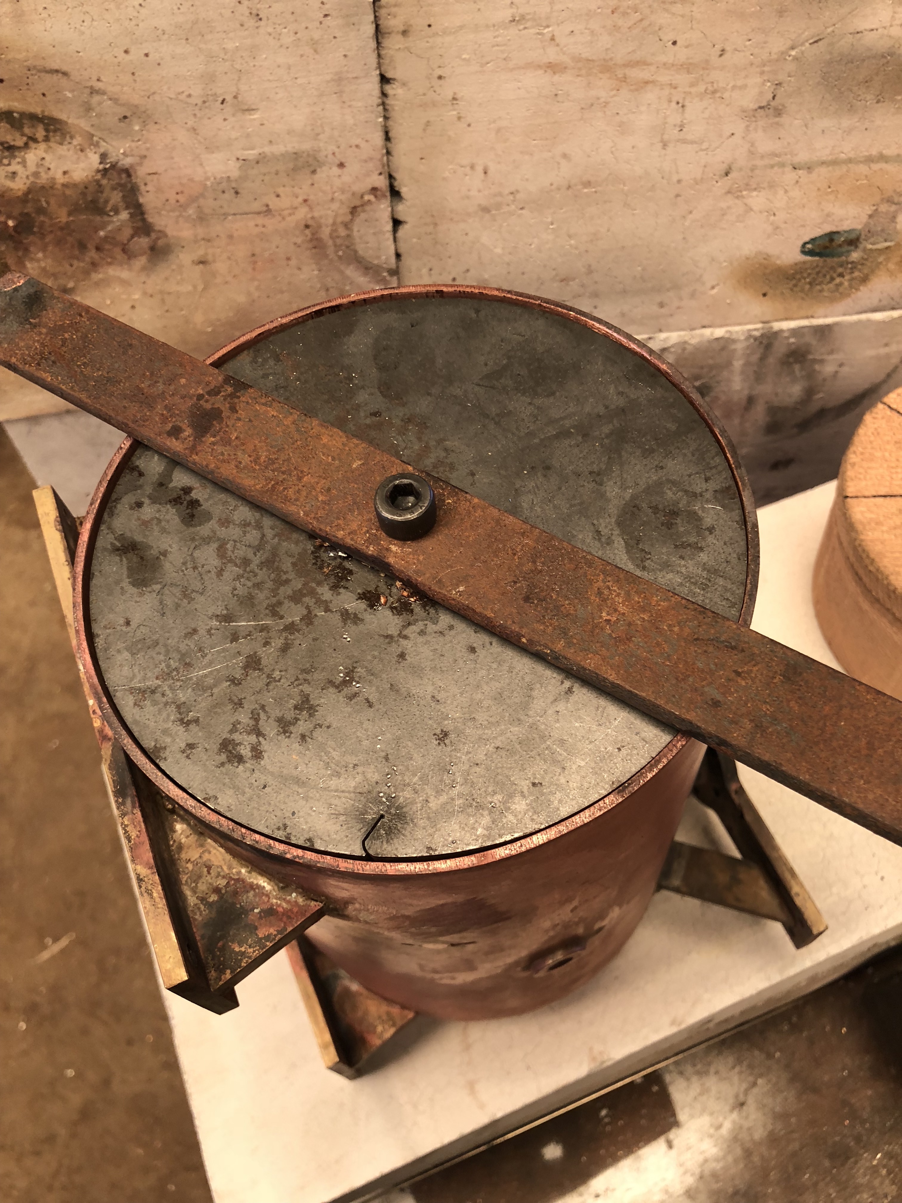
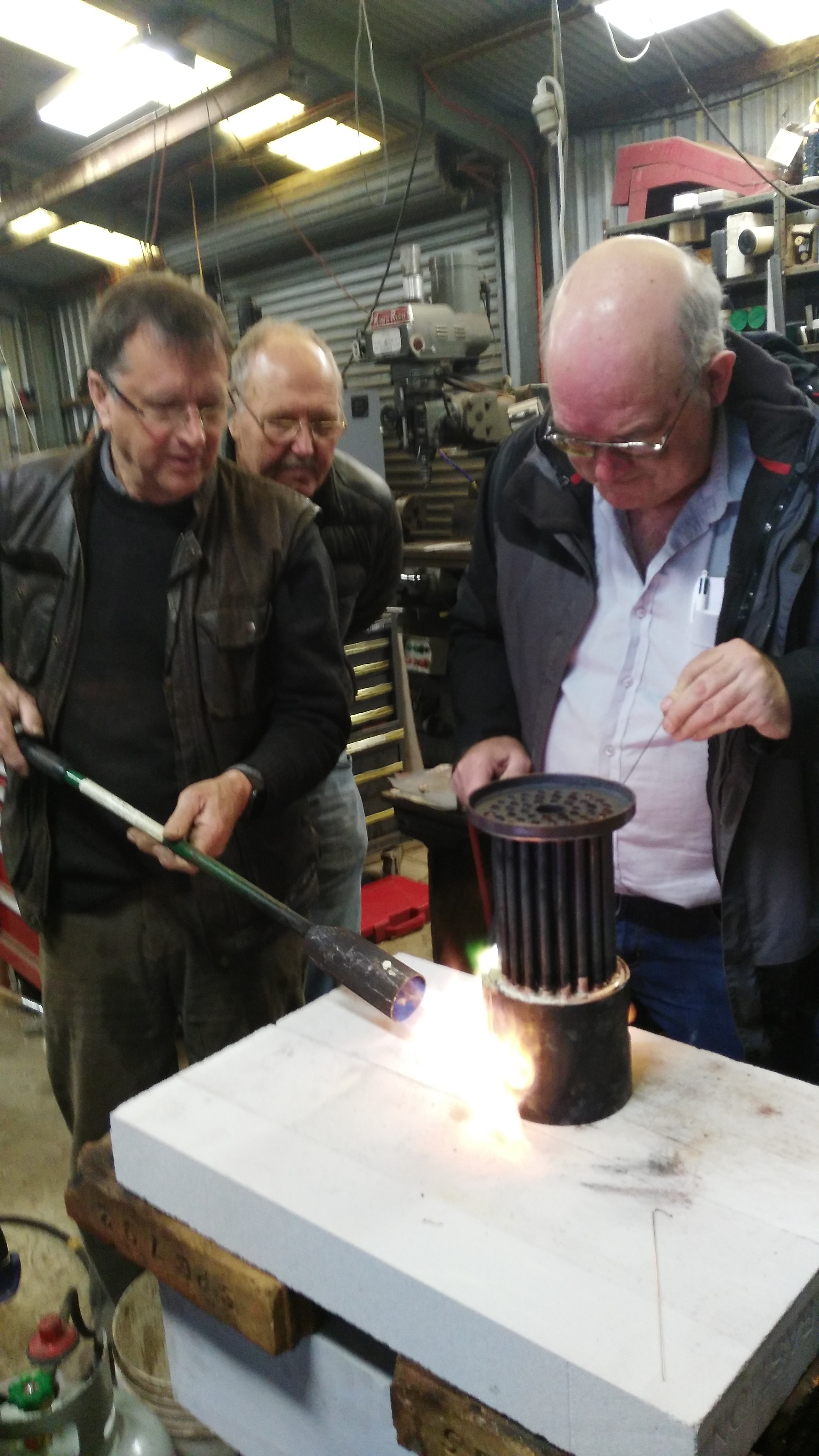
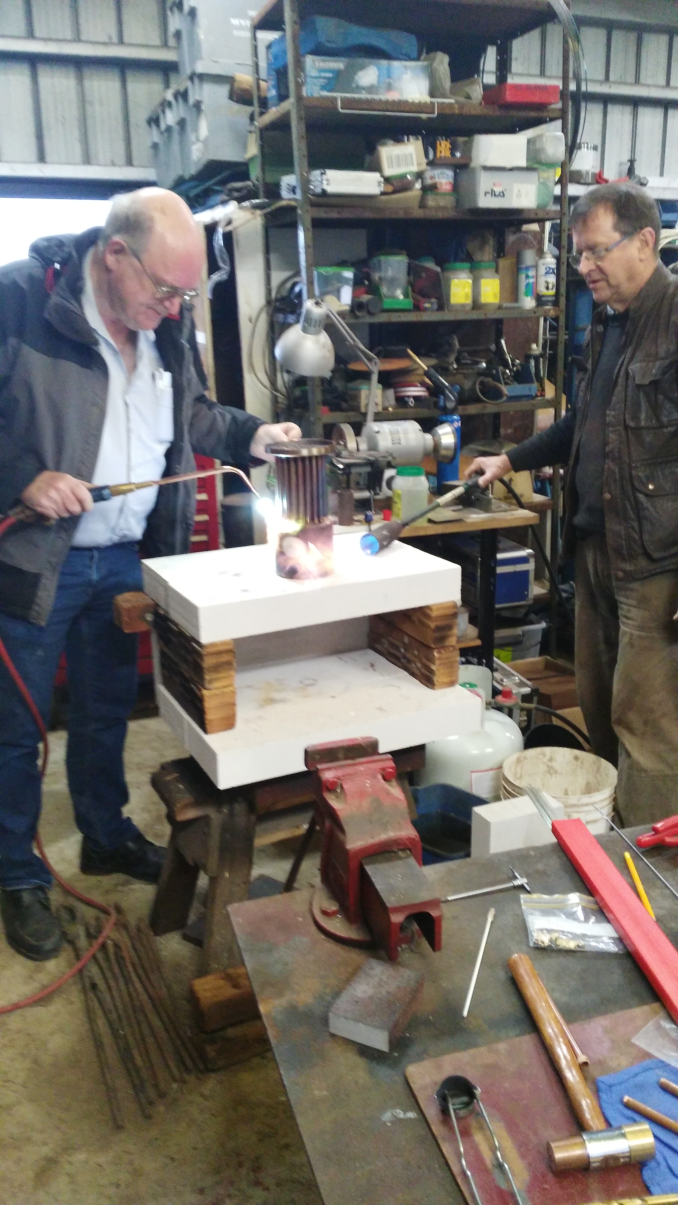
I knew that the wood would catch on fire with the soldering torch, but hoped that it would retain its basic shape until the solder solidified. The steel on top was to hold the ring in position during soldering. If the method did not work I figured that I could make an aluminium shape to replace the wood.

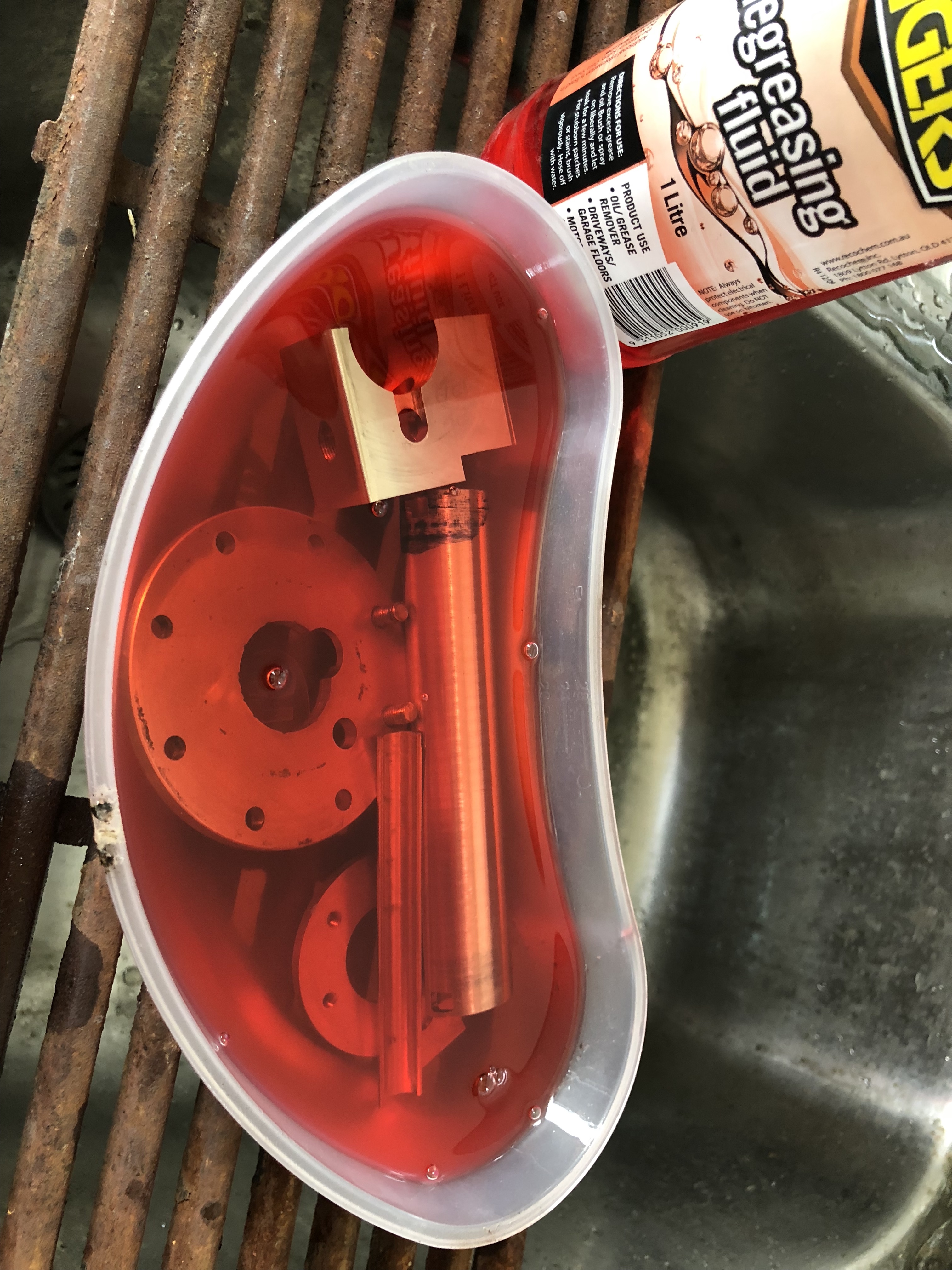
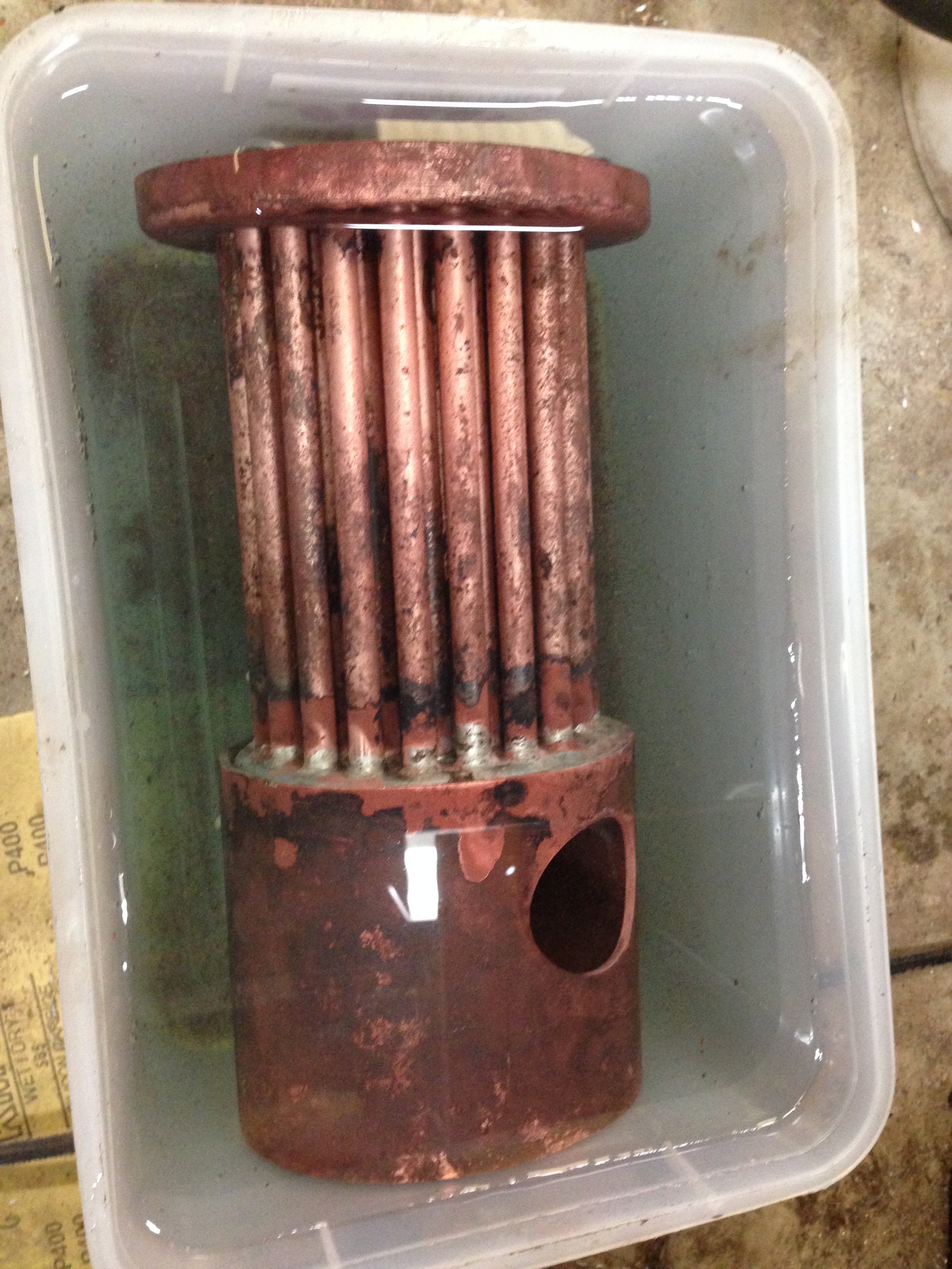
After soldering, I put out the fire by dunking the assembly in a bucket of water.

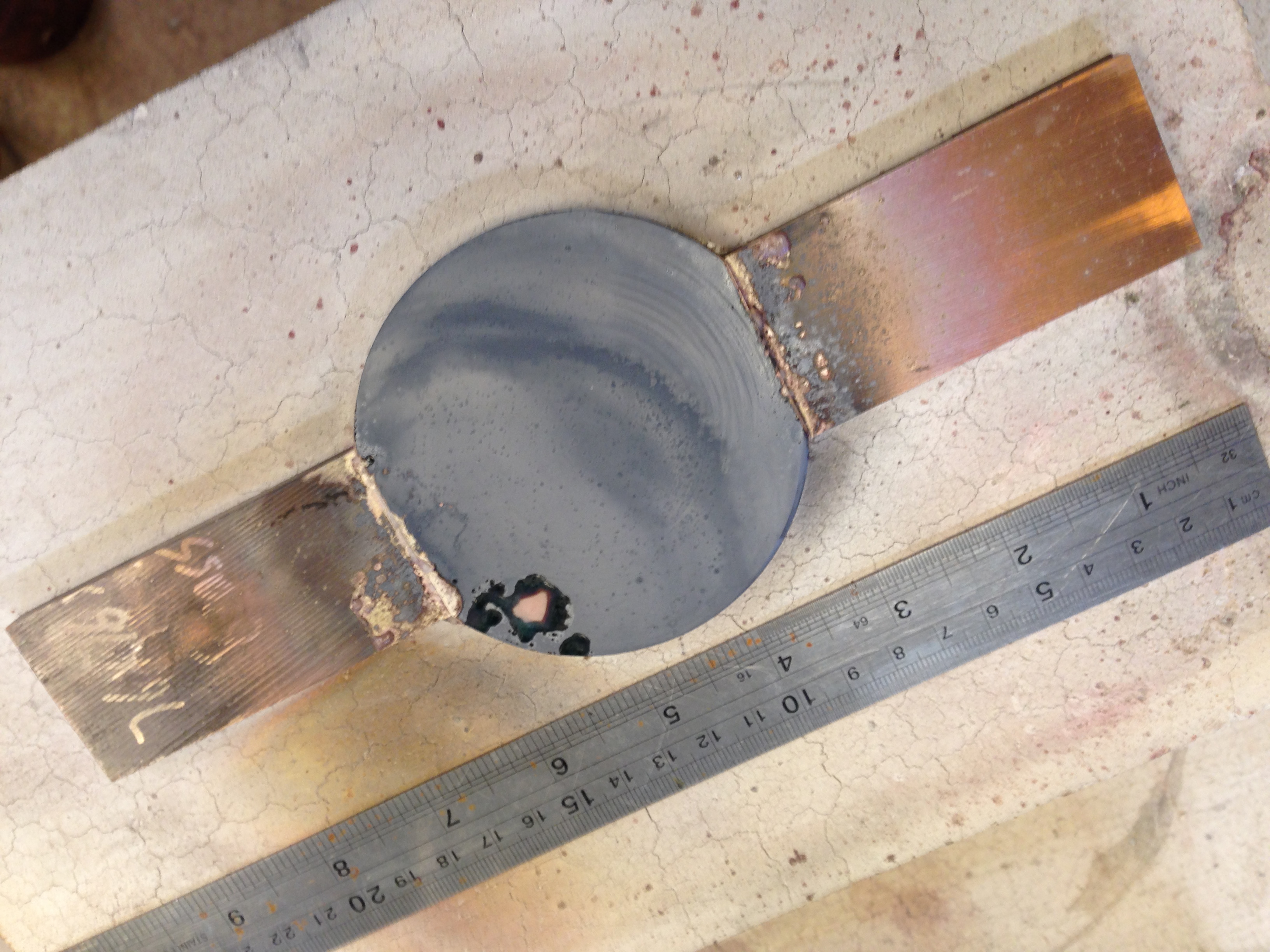
And it cleaned up quite well. Now to carve rebates in the transom so the bracket sits flush with the wood surfaces.

The circular cutout is to allow the end of the Smith’s Screw to protrude under the transom.

Not much to show for several hours in the workshop, but it’s better than working. And best of all the method was successful.

Typists Correction Fluid

WTF! I thought that this site was about model engineering, metal working etc.

Well. I just need to say that typists correction fluid is an essential tool in my workshop.

Not for typing, I hasten to add. But for silver soldering….

Today I needed to silver solder an extra 1mm thick disk to a tiny part, which already had 2 silver soldered joins. I had spent an entire workshop session designing and making the part, and I did not want it to fall apart when I added an extra component. Which I admit, was an afterthought.

And the central hole in the extra disk HAD to line up precisely with the threaded hole in the previously made part.

I had been advised by another GSMEE member that a metal surface painted with typists correction fluid WILL NOT accept silver solder. I have tried this method once before and it works. This is another demonstration.

In front of the correction fluid is the part, with the extra 1mm disk, silver soldered with the 2mm screw holding the parts together. And after soldering, the screw came out. It was not soldered into the assembly because it was coated with the correction fluid.
So annoying. WordPress used to enable rotating images. Not now. So these are the components to be silver soldered. Fluxed. And parts which I do NOT want soldered are coated in the correction fluid.
The work rests on brass blocks to function as heat sinks, to protect the existing soldered joins. This shot shows the workpiece after soldering. Has the correction fluid worked? Well, you have already seen the evidence. Amazingly, it does work.

This handle locks the elevation gears into position after the cannon barrel elevation has been set. Several more hours were required to file a central tapered ridge into the added material, and a corresponding groove where it rests. It all worked out OK.

Typists Correction Fluid. I hope that it never disappears from OfficeWorks.

Thanks again Frank Marrian GSMEE, and jimmymouse, for this great tip.

Armstrong RML Cannon Trunnions – 2

Silver soldering the trunnions into the barrel and the squared blocks did not go well.

For a start, I did not know the composition of the steel of the barrel.  The trunnions were/are silver steel, and the blocks were mild steel.  So it is possible that I did not use the best flux.

And the barrel is quite hefty, so I knew that it would require a lot of heat to get it to temperature, and to keep it at soldering temperature.  So I used a large oxy-propane torch, and heated it to dull red heat.

IMG_8585

The steel pieces fluxed and wired together, ready for heating

IMG_8586

It was a cool day, but the heat output from the red hot barrel was ferocious.

P1053720

Soldered, but one side was not good, and a hammer blow dislodged it.  Damn.

P1053719

The good side, partially machined.

I dithered about how to deal with the faulty side.  I was not enthusiastic about re-soldering it, expecting that the good side would fall apart.

So I cleaned up the pieces, and used high strength, high temperature, Loctite 620, to join the pieces.  The machining will test the strength of the joins, so I will give it the full 24 hours before testing it.  This is the “reject” barrel.

P1053726

Still pondering how to join the trunnions of the “good” barrel (front).  I will discuss it with my colleagues tomorrow when we have a Model Engineering Society meeting on “Zoom” video link.  The 3D printed barrel at back is a handy “how it should look” example.


Soldering the Trevithick Dedger Engine

That is soldering.  Not soddering.


IMG_7082.jpg

These are the engine cylinder, valve chest, steam pipe (on the side of the cylinder), and flanges, pushed together.  I took this photo, because never again will these bronze parts look so pristine. 

IMG_7083.jpg


IMG_7084.jpg

Firstly, a thorough soak in degreaser, then rinsed in water.


IMG_7085.jpg

Then the steam transfer tube was wired into position.   All joins were fluxed, then silver soldered.   Then a soak in sulphuric acid and a water rinse.  


IMG_7089.jpg

The 20mm bore still accepted a 20mm diameter silver steel rod (i.e. no significant distortion from the heat), so the rod was super glued in place, and used to turn the flanges flat and perpendicular to the bore.


IMG_7090.jpg

The assembly was heated to release the super glue.


Trevithick Dredger Engine- soldering the big boiler flange.

Today I soldered the large flange which holds the flat end plate, to the boiler shell.  The flange is a large piece of LG2 bronze, but it is quite delicate because the centre is removed, leaving only the rim.

Here is a photo of the flange in position, fluxed, and ready to apply heat and silver.

IMG_2001.JPG

But before this step I made a special tool.  Can you guess its purpose?


IMG_3667.JPG

It is a disk of 12mm thick steel with a steel bar bolted to the surface.   A hint….  the disk diameter is slightly less than the internal diameter of the boiler shell.


IMG_5064.JPG

Here is the tool in use.  With all of the heat from yesterday’s brazing, the boiler shell had distorted slightly, and the flange to be soldered was a bit tight in places.  So I identified the tight spots, placed the tool against the tight spot, and gave the bar a whack with a hammer, slightly expanding the tight spots.   After this, the flange dropped into position easily and nicely.


IMG_2891.JPG

After soldering the flange.  No video I’m afraid.  Not enough hands.   To minimise the risk of the flange distorting with the soldering heat, I rested it on a plate of flat steel during the soldering.   Note the different shape of the forge for this braze.   


IMG_6804.JPG

And after the brazing, the end plate was nice and square.


IMG_0640.JPG

Square in both directions.


Trevithick dredger engine – second silver soldering session.

Soldered the bushes, the boiler supports, and the engine support.  Did not quite have time to tackle the boiler main end flange.


IMG_8988

The LG2 bronze bushes were made yesterday, and the holes were prepared.  Today I fluxed them and silver soldered.  45% silver, cadmium free.


IMG_1299.JPG

After soldering, and before the sulphuric acid soak.  The Hebel blocks are ideal for setting up the forge area to a particular size and shape.


IMG_3236.JPG

The boiler is upside down in this photo.  I have just soldered the engine support.  Looks messy doesn’t it.  But it looks much neater after the acid soak.  And the splodges will vanish after eventual painting.   I used the bolt in the bush to get the support level and straight, while soldering.


IMG_6550.JPG

Then the boiler supports were soldered, and the unit was dipped in 20% sulphuric acid for 15 minutes, after slow cooling.  Note the Plimsoll line, which was the depth of the acid.  I was unsatisfied with the alignment of that boiler support, so I reheated it and tapped it into a better position.  If it leaks steam, I might need to touch it up, but at least it is properly positioned.


IMG_3493.JPG

At the end of this session.  The big flange is just sitting there, waiting for soldering in the next session.


Actually, this was not the first brazing session.  It was the third.  I had previously silver soldered the firetube.  And if you have been watching this build you might recall that I bronze brazed the domed boiler end and the boiler wrapper, and the vertical cylinder into the domed boiler end.  Despite the copper reaching red heat during today’s session of silver soldering, the bronze joins remained intact.  Bronze has a higher melting temperature than silver solder.  Which was one reason I did the bronze brazing first.


Trevithick Dredger Engine- First silver soldering session

Today I fitted the chimney right angle piece, drilled and soldered on its flange, and drilled the end plate to accept the flange.  Then I CNC drilled the big bronze end plate to accept the flange.


IMG_6880.JPG

The angle piece is a commercially available plumbing part.  The stainless steel square nuts came from China.  Joins are silver soldered.  In a departure from the Tubal Cain/Julius deWaal plans, I decided to attach the chimney flange directly to the flat end plate.  I reckon that’s what would have been done in 1806, and it is what shows in the 1820 Rees Encyclopaedia drawing.   Note the unwanted threaded holes, now filled with stainless steel threaded rod.

Then I carefully positioned the bronze end plate, the firebox and the firetube, and silver soldered them together.


IMG_6877.JPG

The parts are fluxed and pushed together, ready to apply some serious heat and expensive silver.


IMG_6878.JPG

Not pretty, but I am happy with the silver joins.  Minimal retouching required.

Next, the inspection hatch will be soldered to fill the rectangular hole.

Then the main bronze flange will be permanently attached to the boiler shell.  I intend to silver solder it, but considering bronze brazing.


Trevithick Dredger Engine- Supports

IMG_6698.JPG

These are the boiler supports for th Trevithick Dredger Engine, which need a little more finishing.

Error
This video doesn’t exist

As you can see my CNC mill is working nicely.  The slow feed rate is because the brass is just super glued to the mounting base and I did not want to risk it coming adrift.

IMG_6696.JPG

The CNC milled parts.  The brass is 7.5mm thick.

IMG_6697.JPG

And this was cut out from the edge silver soldered brass bread slices.

And I have also been working on the 6″ vertical boiler.  The brazing with silver solder is almost finished.  I have been redoing some of the joins, and can now get the pressure up to 200psi.  There are 101 soldered joins in the construction (so far), so I am not too upset that a few of them were not perfect and required a redo.  SWMBO was wondering about the bills from the industrial gas supplier.  I have used several fills of oxygen.  Totally abandoned acetylene and using propane now.  It delivers more heat (at a slightly lower temperature), and much less costly.

IMG_6700


How to make small bits of brass (or bronze) into big bits of brass (or bronze).

I needed some brass plate 6mm thick, 50mm wide and 150mm long for the Trevithick boiler-engine..

Prices on Ebay were horrendous for thicker material, and I could find no local supplier.

Silver solder, when properly used, is said to be as strong as the parent metal.

And I had some 75 x 75mm brass square section about a meter long.  I bought it years ago for a project and most of it was unused.

So, I cut some slices off the end, sliced bread fashion, and silver soldered pieces together.

IMG_6684

2 Bread slices of brass (centre) and machined joined pieces on the sides.

IMG_6685.JPG

The square section brass log (I can barely lift it), 2 slices at the back, and 2 pieces edge silver soldered and surface machined.

I also needed a large thick piece of LG2 bronze for the Trevithick dredger engine.  The middle round piece needed to be bronze because it is exposed to boiler pressure.  The outside pieces could be bronze or brass so I used brass.

IMG_6687


So I silver soldered brass edge pieces to the central piece of bronze.  The soldering was done on the very flat Hebel aerated concrete block,  and the final piece was very flat, requiring minimal machining.

IMG_6688


This is the non machined underside of the brass-bronze-brass piece.  It has been rubbed on a surface plate covered with emery paper, just to demonstrate the flatness of the soldered piece.


6″ Vertical Boiler- First silver Brazing

So what is the big deal?

Well for a start, this is a big deal financially.  The materials to be joined are expensive, and some are difficult to obtain.

And the silver solder itself is expensive.  We ended up using 4 sticks of 45% silver solder, and an unknown quantity of oxygen, acetylene and propane.

And the end result will be inspected by an expert boiler inspector, and if it is substandard, it will be rejected.  No argument.

So yeah, it was a big deal.  Look at the pics.   A few friends called in to watch and help.  It was a cold wet winter day, and I had the workshop wood heater working to keep the troops happy.

IMG_6578.JPG

I used steel wool to expose the elemental copper.

IMG_20180711_141605

Me applying flux.  Note the silver solder rings which were made on the lathe.  Don’t ask where the brush originated.

IMG_6580.JPG

The firebox wrapper was placed on the aerated concreted form to keep the tubeplate level, and allow the tubes to penetrate exactly 2mm.  The tube ends were fluxed, and silver solder rings placed into the join.

IMG_6582.JPG

The 44 fluxed firetubes with their rings of silver solder are in place.  The top tube plate will not be brazed at this time.  It is there to keep the firetubes in the correct position.  The firebox tubeplate is also fluxed and sitting in position on its Hebel block.

IMG_20180711_151431.jpg

Me on the left with the propane weed flamer applying gross heat, Stuart with oxyacetylene applying local heat and silver solder, and Swen cheering.  Brendan is the photographer, trying not to get burnt.

IMG_20180711_151114.jpg

We probably should have reshaped the forge to reflect the heat more efficiently.

IMG_6584.JPG

When the brazing seemed to be finished, the work was allowed to cool to 200c, then quenched in water then a 15″ soak in 20% sulphuric acid to remove any remaining flux, then a further water soak to remove any acid.  Yes, the top plate is upside down.  Yes, it will be reversed eventually.

IMG_6586.JPG

Inspection from inside the firebox.  Most firetubes have taken the silver solder properly, but a few of the inner circle and the flue require a second application.  The brazing heat looks to have been inadequate near the centre, probably due to the density of the firetubes.

So, not a perfect result, but not bad for a beginner.  Stuart opined that the job would have been better if my silver solder was the older, (more dangerous) but more runny type which contained cadmium.

6″ Vertical Boiler, Using Clekos, and dropping the Traction Engine into a hole.

Tha firefox wrapper is made, and today I fitted a butt strap.  The butt strap will be riveted to the wrapper, and brazed later.  In order to drill the rivet holes, the parts needed to be held together, Clekos proved perfect for the job.

IMG_6476.JPG

Using the external clamping Clekos to keep parts in place while I drill the first hole.

IMG_6477.JPG

Then as each hole was drilled an internal Cleko was inserted.  Worked very well.

Then, a Bit of fun on the TRACTION ENGINE

Oh Bother.  Where did that hole come from?  And why isn’t this traction engine a 4 wheel drive?  Had to uncouple the trailer, and two men to push it out of the hole.

The redesigned steam regulator worked very well, as did the steam driven suction pump.  The new oiler filled up with steam, so I need to fix the non return valve.  Probably a bit of grit in it.


Cannon Trunnions

I am unsure whether the trunnions are the semi circular holes in the carriage, or the cylindrical bits of the metal barrel which support the barrel.   I am going to assume that the trunnions are the part of the barrel.  (I checked.  The trunnions are the cylindrical parts of the barrel which support the barrel.)

So, today I made some trunnions and silver soldered them to the barrel.  In the full size original version they would have been part of the barrel casting.

But before that, I polished the barrel with a Scotchbrite type pad, impregnated with some polishing compound.  And it made the barrel sparkle!

cannon - 1.jpg

Then I attached the knob at the breech end, M4 threaded rod attachment.

cannon - 2.jpg

cannon - 4.jpg

Looks OK, Yes?  This protrusion would also have been part of the cannon casting.  It was used to attach the huge ropes which limited the recoil movement when the cannon was fired.  


cannon - 3.jpg

Turned some brass for the trunnion.  It was later cut into two pieces.

cannon - 7.jpg

Drilled the holes with an endmill in the barrel for the trunnions.  Stopped short of the bore by 3mm.  Jerry Howell specified threaded trunnions, but I decided to silver solder them in place.

cannon - 8.jpg

This is my silver soldering forge, for this project. (actually a hearth).   The barrel is still a hefty lump of brass, and I predicted that a lot of heat would be required to raise it to a suitable temperature.  The base is steel, and the bricks are fire bricks.  I used oxyacetylene as my heat source.

cannon - 9.jpg

After the silver soldering.  Not quite so pretty now.  I waited an hour before I could handle the hot item.  Note that the spigot in the bore which was Loctited in place, has come out.  Eventually, I became impatient, and applied wet rags to speed up the cooling process.

cannon - 10.jpg

Then a soak in dilute sulphuric acid for 15-30 minutes, to remove the flux.

24000 RPM spindle for CNC Mill 2

Yesterday the spindle was wired to the Variable Speed Drive – single to 3 phase converter, and to power. It span smoothly and quietly, and very fast.  Much quieter than a woodworking router of similar power and RPM.

Today I hooked up the coolant, after testing the pump.  But when I ran the coolant through the spindle, there was no movement of the coolant.  So I reversed the fluid connections in case it was direction specific, but still no action.

The pump and lines were OK, so there was a blockage in the spindle.

I removed the coolant connectors on the spindle, and I could see something white and foreign deep in the works.  A bit of poking around revealed that it was probably a bit of packaging foam.  I dug out some, then blasted the rest out with compressed air.  Testing with the compressed air showed that the way was now clear, so I reinserted the supplied fittings.

And one of them snapped level with the surface of the spindle cover.  Bugger bugger.

I managed to get the broken buried thread out of the spindle using an “Easy Out”.

The broken fitting looked complex.  I certainly did not want to wait for one from China, and I was very doubtful that it would be available locally.  I could have made one, but it looked like a half day job.

So I silver soldered it!

The top of the spindle.  The fittings, with the broken one on the left.

The top of the spindle. The fittings, with the broken one on the left.

The coolant fitting and its broken thread, fluxed and ready for silver soldering.

The fitting in position for silver soldering. Resting on a nail held in a vice.

IMG_2723

The fitting after silver soldering. The threads needed to be cleaned up by running a die down them

This is the setup during the first engraving job.

This is the setup during the first engraving job. The green fluid is the coolant.

Engraving a small brass plate, at 20000 rpm.

Engraving a small brass plate, at 20000 rpm.