machines which I have made, am making, or intend to make, and some other stuff. If you find this site interesting, please leave a comment. I read every comment and respond to most. n.b. There is a list of my first 800 posts in my post of 17 June 2021, titled "800 Posts"
Actually, the wooden slides were used on other British garrison cannons as well as Armstrongs. For example, at Flagstaff Hill, Warrnambool there is a 68pr LowMoor mounted on a wooden slide, which is identical to the slides used for the Elsternwick Armstrong 80pr’s. And I have a drawing of a breech loading 110pr which was also mounted on an almost identical slide. The only differences were in the carriages, and those differences were minor, depending on the diameter and weight of the various barrels.
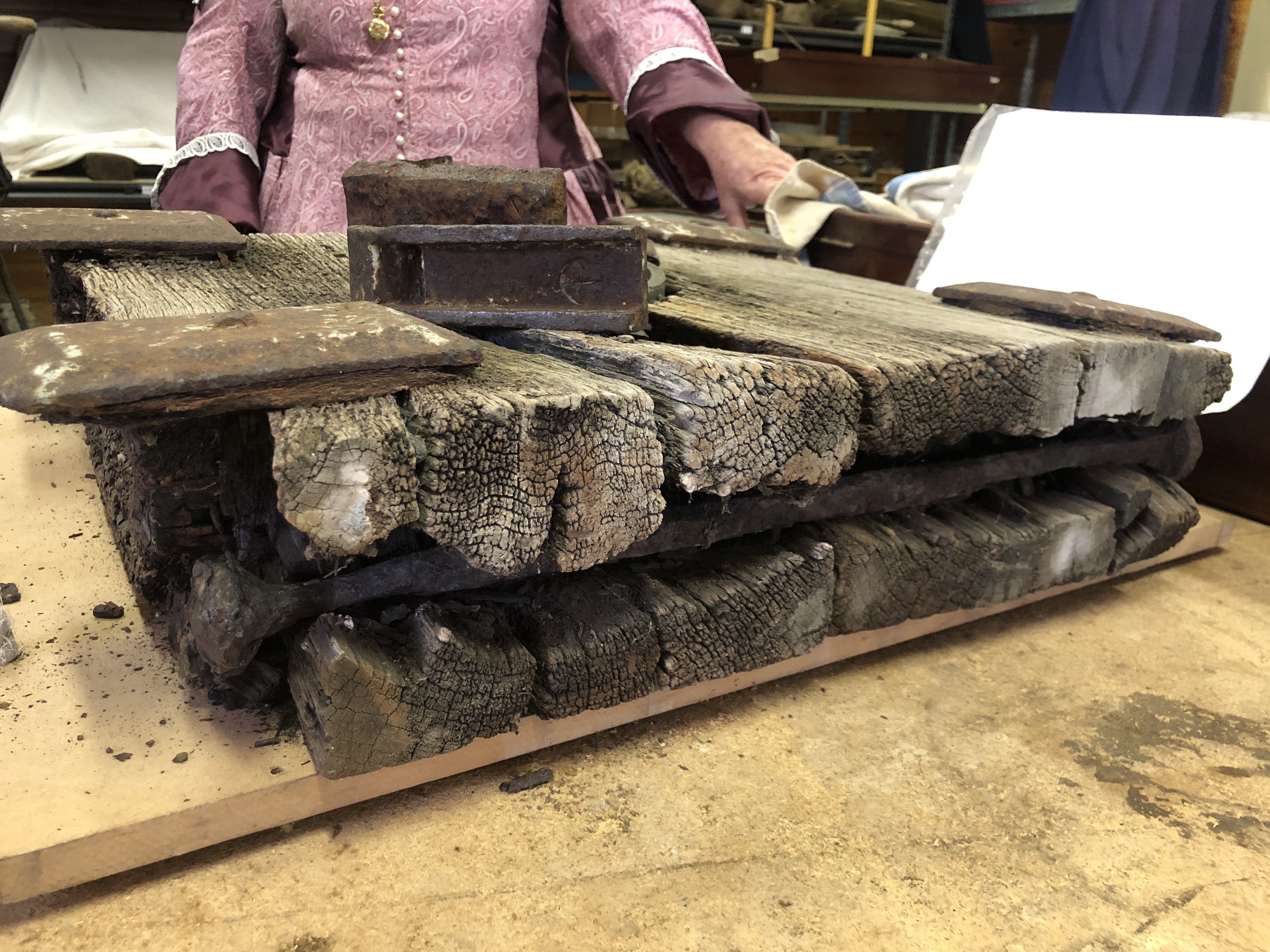
So I have used measurements from several slides, located at Port Fairy, Warrnambool, and Elsternwick. The Warrnambool slide is unrestored and badly rotted in some places, allowing inspection of the interiors of the big longitudinal beams. The Elsternwick slides have been restored, painted, and have metal protective covers, which conceal details of the metal strips on the tops of the slides. The Port Fairy slides have been extensively and expertly restored.
And there are always compromises to be made when scaling down structures by a factor of 10. Fasteners for example are only approximately the scale dimensions.
Here are some pics of progress to date on the slide…
The metal strips are stainless steel. Not authentic but should polish nicely. 30 countersunk screws per side. I superglued the slides in position, then centre drilled, drilled and countersunk the holes. Getting the countersink depth was tricky and required a lot of trial and error on each hole. Then I filed any protruding bits of screws flush with the slide surface.
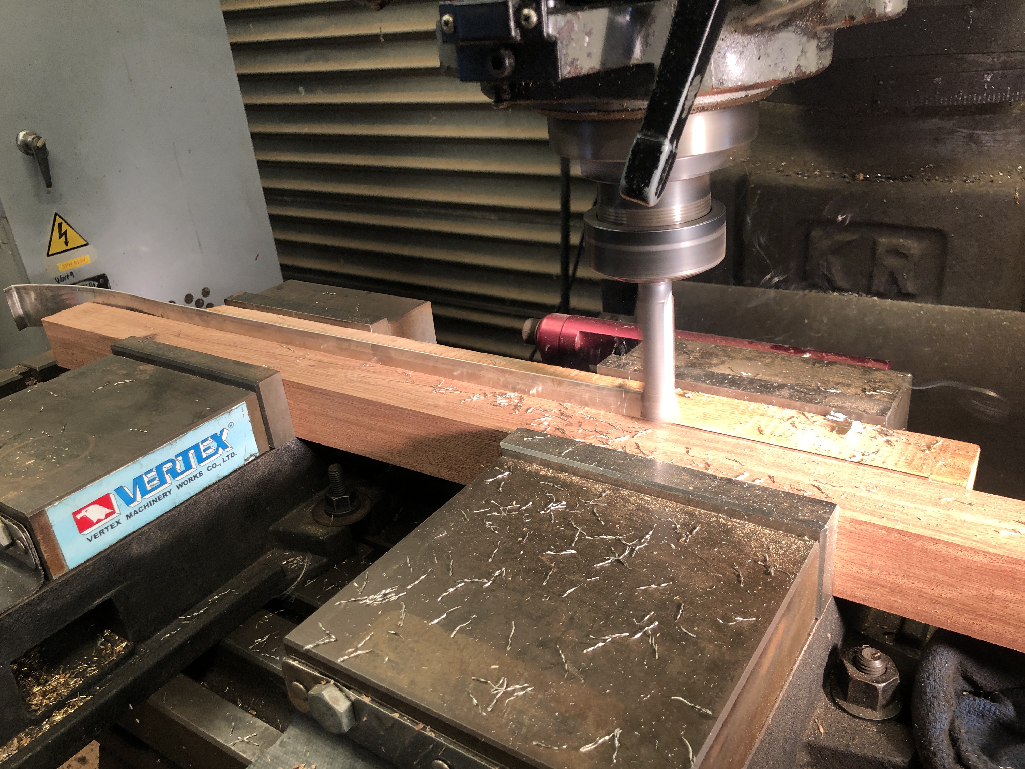
To shape the stainless steel strips, on Xmas Eve, I roughly bandsawed them to shape, then milled the edges to end up with 23mm wide strips, 480mm long. The steel is only 1mm thick, so holding it for milling required some planning. Guillotine or laser cutting would have been preferred, but not wanting to wait until mid January for a pro shop to cut it, I did it myself, using 2 bits of straight hardwood to hold the thin stock in 2 identical vices on the milling machine.
On one of the bits of hardwood I made a 23mm deep cut on a face of the wood, and rested the thin stainless steel on the lip thus formed. Then ran a sharp milling cutter along the surface of the wood, cutting the steel to size. That worked fairly well. As you can see, I removed about 10mm width of the steel in one run. Checked the dimensions, remounted the strip in the bits of wood, and finished the edge milling. Yes, I had to file the edges to remove the sharps. Drilling the fastener holes, after supergluing the strips into position. The large hole is as in the originals, to allow access to the wheel bracket bolts.The wheel brackets are finished, and bolted into position. Wherever possible I am using brass, bronze or stainless steel. A few more parts to be made and fitted, including carriage stops, a wooden bollard, gunners platform and tackle block rings. Then to decide about painting-finishing.The wheel brackets are attached by a bolt which passes right through the longitudinal beams, to be secured with a round nut at the top.
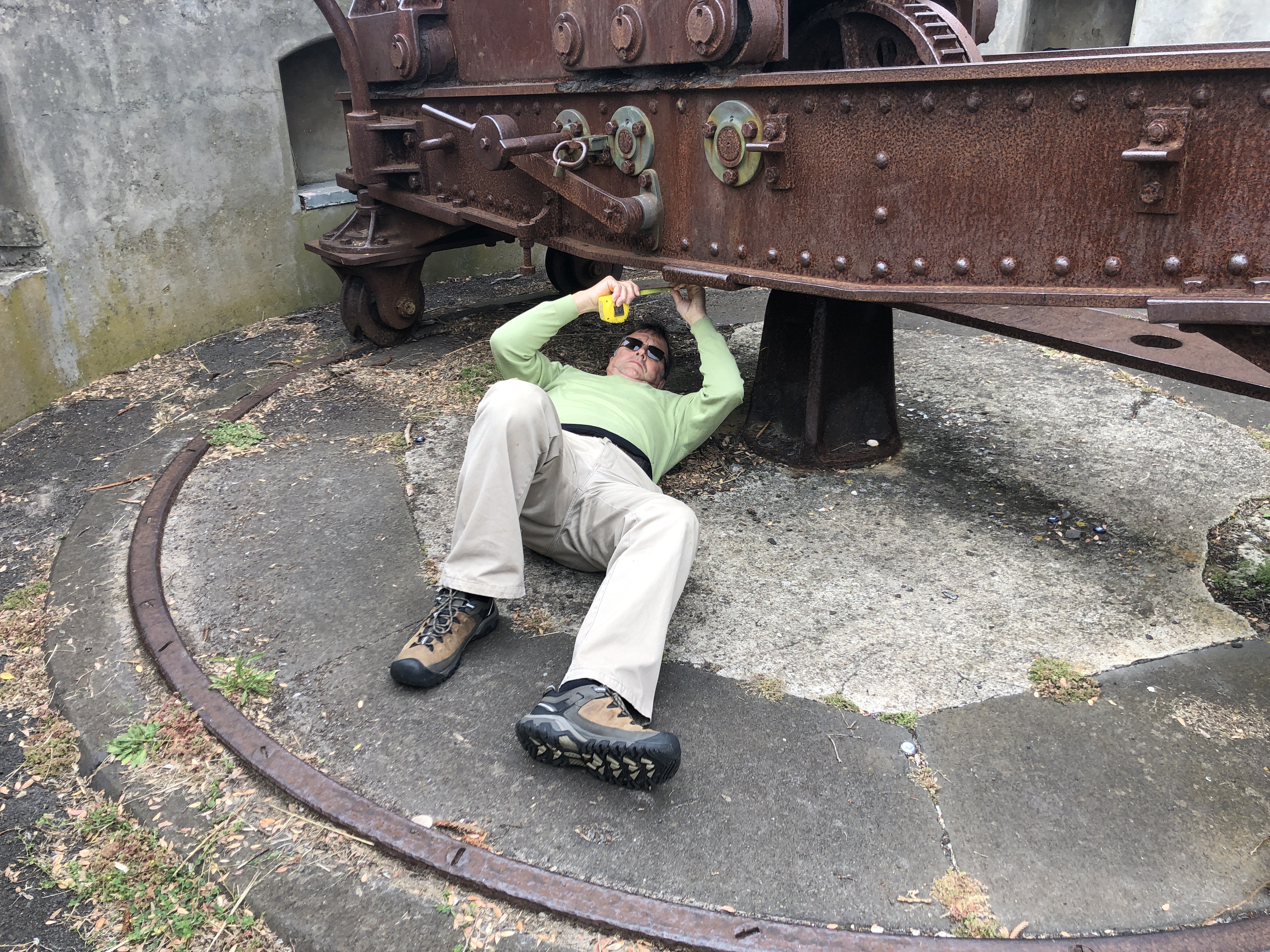
So, today I battled 1.5 hours of post covid lockdown Melbourne traffic to take a closer look at the wooden slide and carriage of this 1866 Armstrong RML cannon which I am intending to model. There are 2 of them in the Hopetoun Gardens, Elsternwick. They are more complex than I had imagined.
The barrel is identical to the barrels which I had modelled on iron slides. The iron slides were a later improvement – modification.
It was a beautiful spring 20ºc day. I spent almost 3 hours photographing and measuring the wooden components. Some parts have been restored, and it was lucky that there are 2 examples to check and compare.
I was climbing over and under the cannon, and groundsman came over to check. Then a pair of grandparents came over with their 5 yo grand-daughter, and a further pleasant conversation followed.
Some examples of the photos…..
And an example of many pages of measurements and sketches…
There are 11 pages filled with details like this, representing my 3 hours.
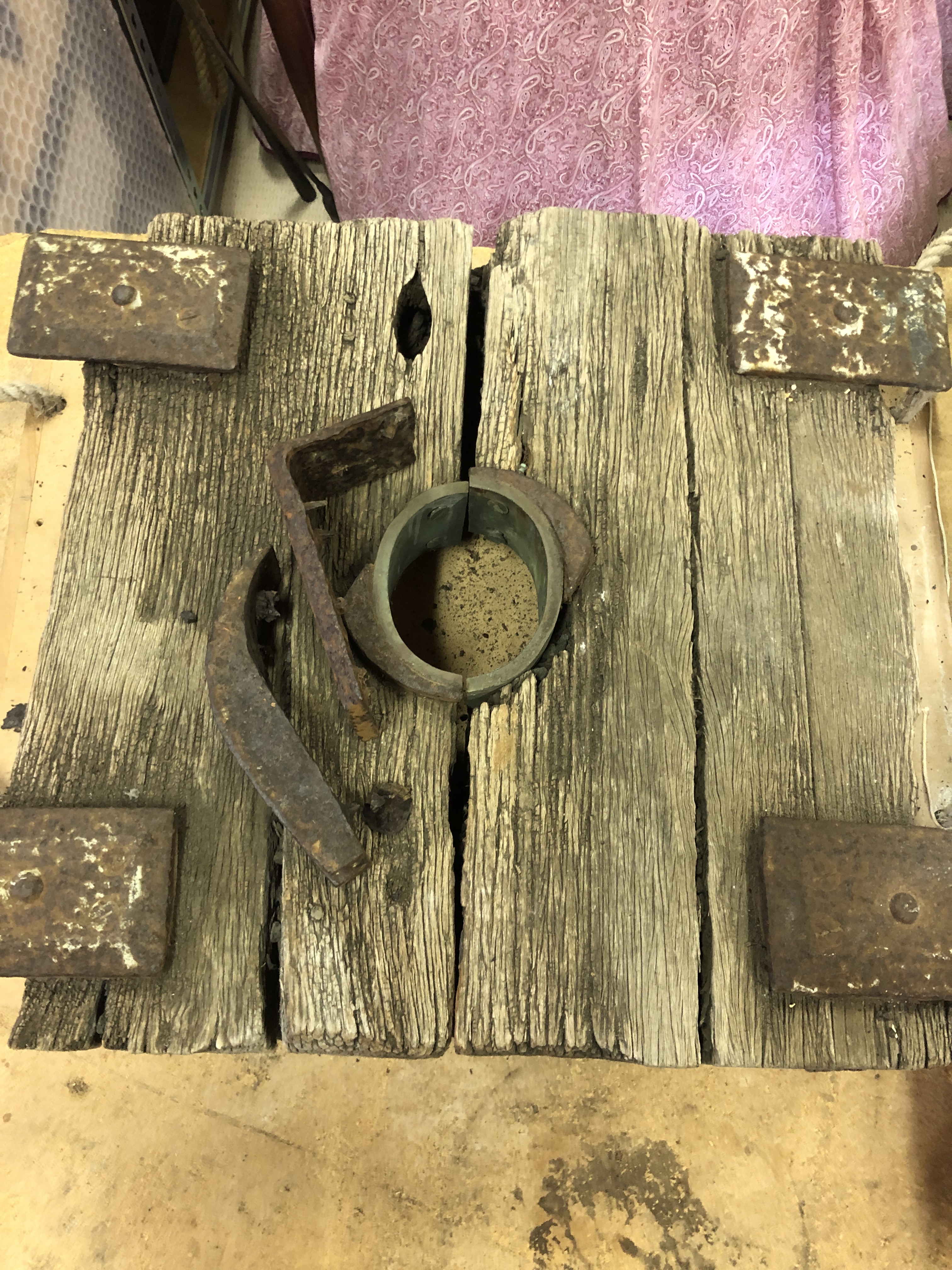
And I still do not understand how the barrel elevation mechanism functioned. It could have been a wooden wedge called a quoin, but there appears to be a metallic disk set into the wooden bearer. Could there have been a screw mechanism which has since been removed/stolen/lost? Pictures on Google Images do not help. Does anyone know?
The sights were the final parts to be made for the model Armstrong RML.
There were reasons for delaying these items. They are tiny, easily dropped and lost, have tiny almost invisible details (to my eyes), and involve fine and very deep drilling into the barrel, on which many hours have previously been expended.
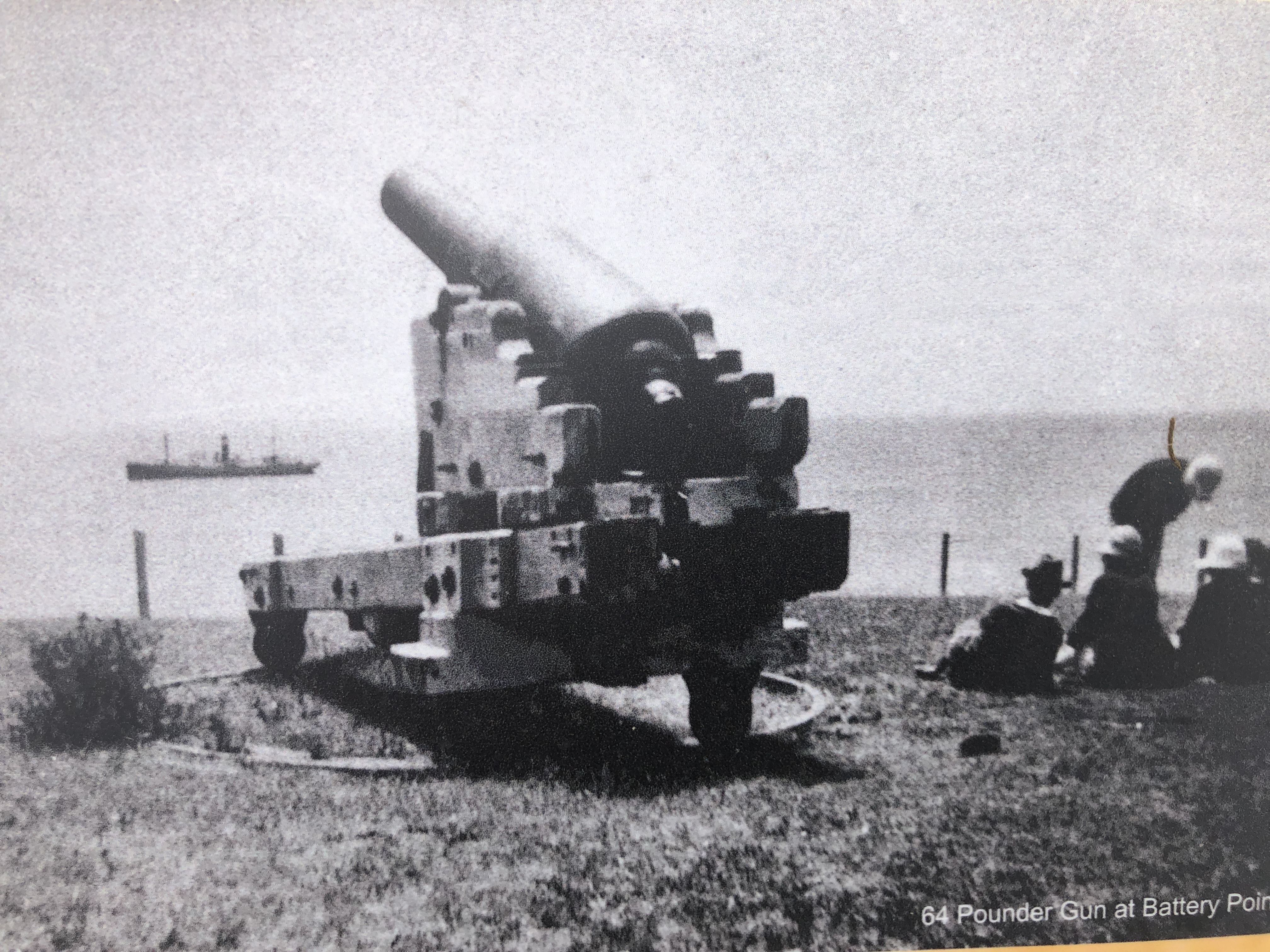
First I looked up every reference I could find about the full size originals. I could find no picture of the sights on the 80pr Armstrong, but I did find some diagrams of the sights on the Armstrong 64pr, on which the 80pr was based. Another problem was that there were rapid developments in sight technology, and I had to decide which period I would choose. The later periods (after 1880) had complexities which did not exist in 1860. In the end I just made decisions, knowing that they might not be exactly correct, but thinking that if further information surfaces I could make and install new sights.
This is the design I chose. The 64 pr had 3 pairs of sights, the 80 pr had only one pair, on the right hand side.
The next step was to drill some 2mm and 3mm holes into the barrel.
The drilling setup. The barrel was held firmly between brass strips. The breech end of the barrel might need a bit more finishing.
First I milled 3mm flats. The first milling bit, solid carbide, just snapped as it bit into the barrel from the side. A HSS bit was more long lived.
A complication was that the foresight was vertical, but the hindsight was sloped 2º inwards to adjust for slight lateral deviation of the projectile which results from the rifling.
Next, a 2mm hole was drilled right through the barrel, missing the bore, and exiting through the bronze bracket which supports the elevation quadrant gear. At 40mm deep that hole qualifies as deep drilling. Tension drilling.
I did not have a long series 2mm drill bit, so I silver soldered an extension, leaving 40mm of the 2mm bit exposed. No photos of the deep drilling. I had other things on which to concentrate. The drilling was actually uneventful.
Showing the drill sitting in the holeFabricating the sights involved silver soldering 0.5mm brass strip to 2mm stainless steel rod. This was the soldering setup. The the sights were shaped by belt sanding and filing.
And now for some sights of the sights on site.
I will polish the sights.Apart from dusting the base, and some final polishing, the model Armstrong cannon is now completed.
When the cannon was fired the recoil pushed the carriage up the 4º slope of the chassis. However, to reload the muzzle loading cannon, the carriage had to be completely at the top of the slope. I know this, from making the model. There is only one position of the carriage on the chassis where the loading arm will properly engage with the muzzle of the barrel.
So, if the recoil did not push the carriage up to exactly the correct position, it had to be wound up to correct position by 2 of the gun crew, operating a handle or wheel on each side of the chassis.
On the first model which I made of the cannon, I copied the wheels which were present on the original cannons at Warrnambool.
One of the Warrnambool 80pr Armstrong cannons, showing the 1 meter diameter winding back wheel.
Of the seven 80pr Armstrong cannons which I have been able to examine, the Warrnambool pair are the only ones with existing winding back wheels or handles. So that is what I made for the first model which I made, and what I had planned and made for the 2nd model.
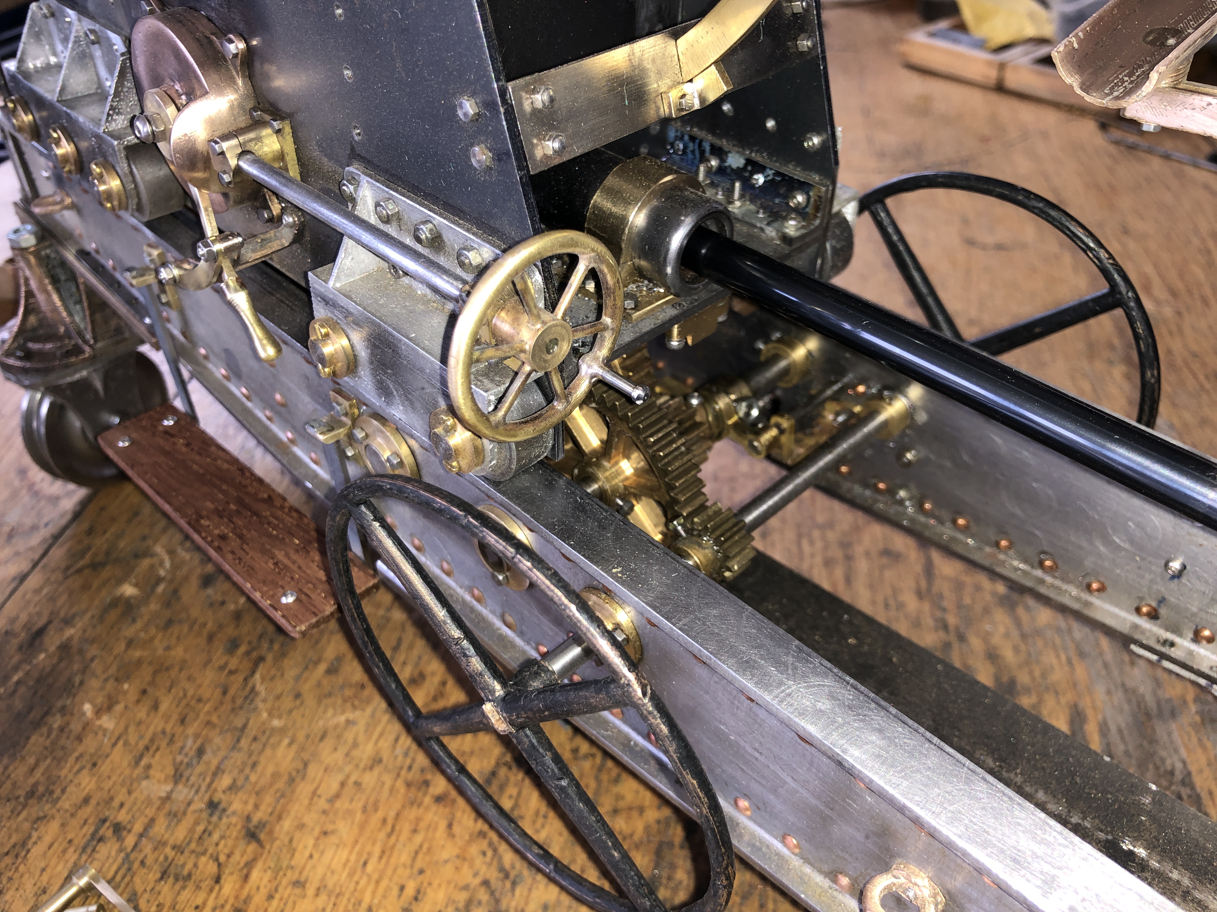
The second model Armstrong 80pr, which I am making for myself. With winding back wheels. They look interesting. But are they original, or later fanciful interpretations?
But, I was always a bit dubious about the large, and rather unwieldy wheels. Would the original Armstrong designers have specified such wheels? Then one of my readers independently questioned the wheels, so I delved more deeply.
The 80pr cannon is essentially a copy of the 64 pr Armstrong cannons, the main difference being in the construction of the barrel. The 80pr barrels used the new method of winding white hot strips of iron around a mandrel, which made them able to accept larger charges of gunpowder, and heavier projectiles.
I could not find any plans or diagrams of the 80pr cannons, but I did find these drawings of the 64 pr’s on a very similar iron chassis….
The dimensions of the 64pr are similar to the 80pr. And can you see the winding back handle, at the front of the winding back gears? It is certainly not a wheel.
So, I have made handles for my 2nd model…..
See the handles? They look the part, No?
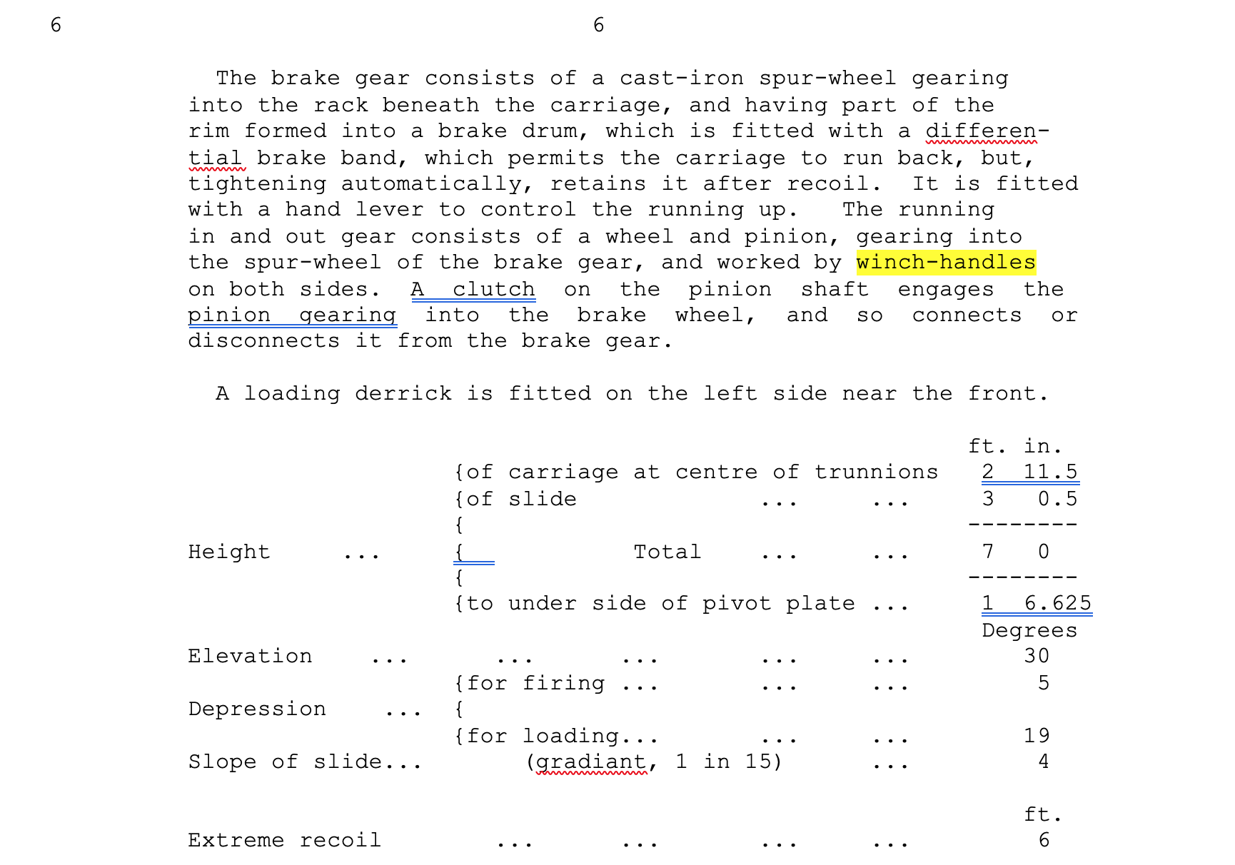
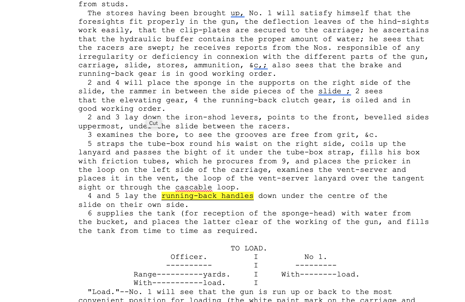
Then, the instruction manual for the 80pr, which I saw for the first time a month or so ago, specifies that after winding back, the HANDLES are laid under the chassis. Not the WHEELS, but the HANDLES.
A copy of the original operating manual for the 80pr Armstrong RML cannon on an iron slide.Page 6 of the operating instructions. Fluoro highlight added by me. “winch handles” could still be the large wheels.Page 10 of the instructions. I really doubt that large wheels would have been easily laid down under the slide. I am fairly sure now that crank handles would have been used. Much easier to use, to remove, to lay down, then replace. Even on the model, the crank handles are easier to use than the big wheels.
So, I rest my case. Crank handles it is, unless some other convincing evidence comes to hand.
P.S. Casting the Chess Men. I am still feeling a bit despondent about that last failure. I have some ideas about better techniques, but I am not moved to try again. At least at present. For one thing, the failed pieces are really quite heavy, and I wonder whether even if successfully made, they would feel good to use. So I am moving back to finish the cannon, and will wait see if there is some inspiration to redo the chess men. Also, I am still fixing the CNC lathe with the dead computer. Have changed the interface to a smooth stepper, and laptop, but there are still some issues. Stuart T installed the smooth stepper, and reconfigured Mach 3, but the smooth stepper would not work. So Stuart used another identical smooth stepper board, and that works. Stuart is still trying to figure out whether I bought a dud smooth stepper board.
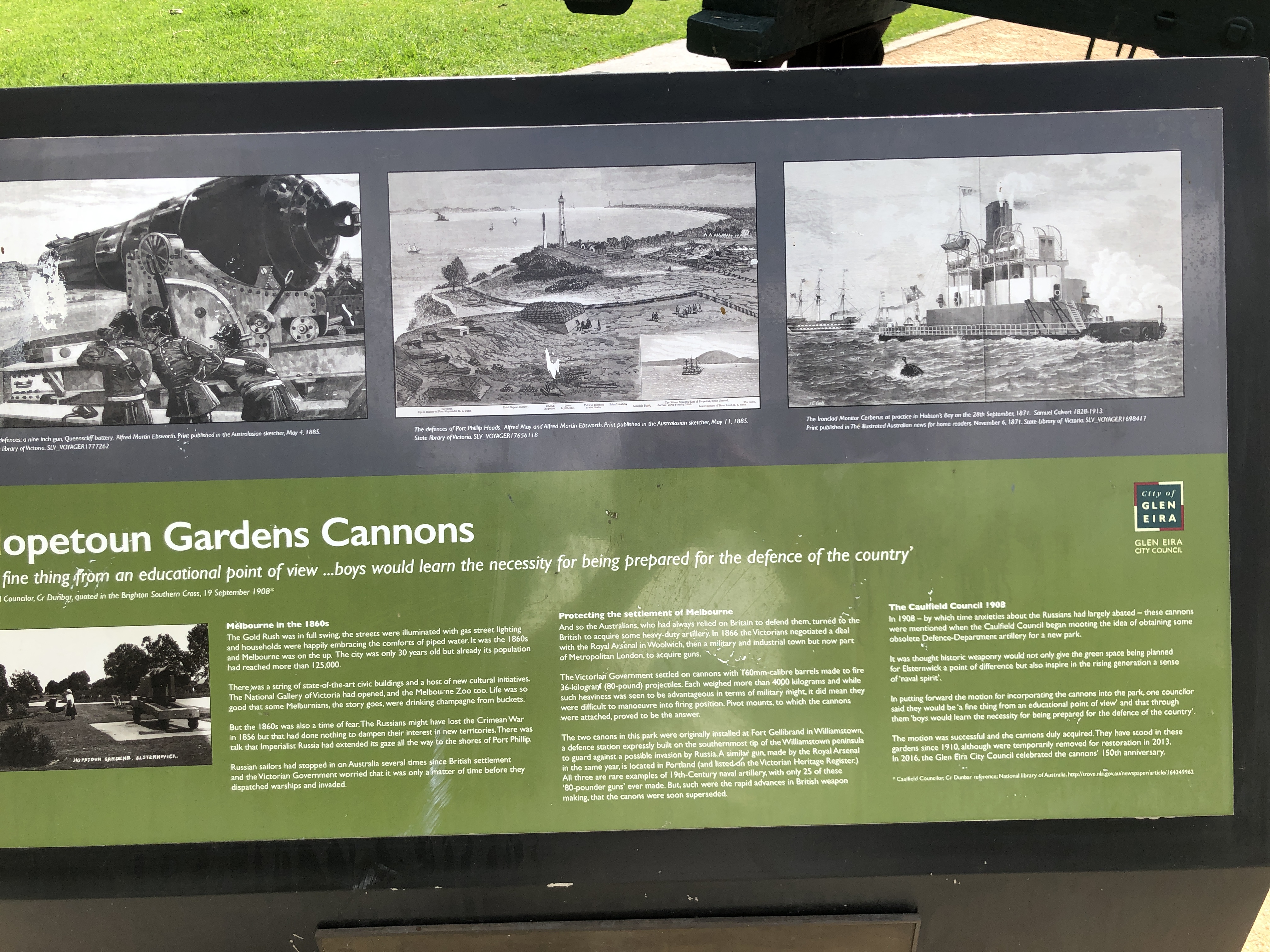
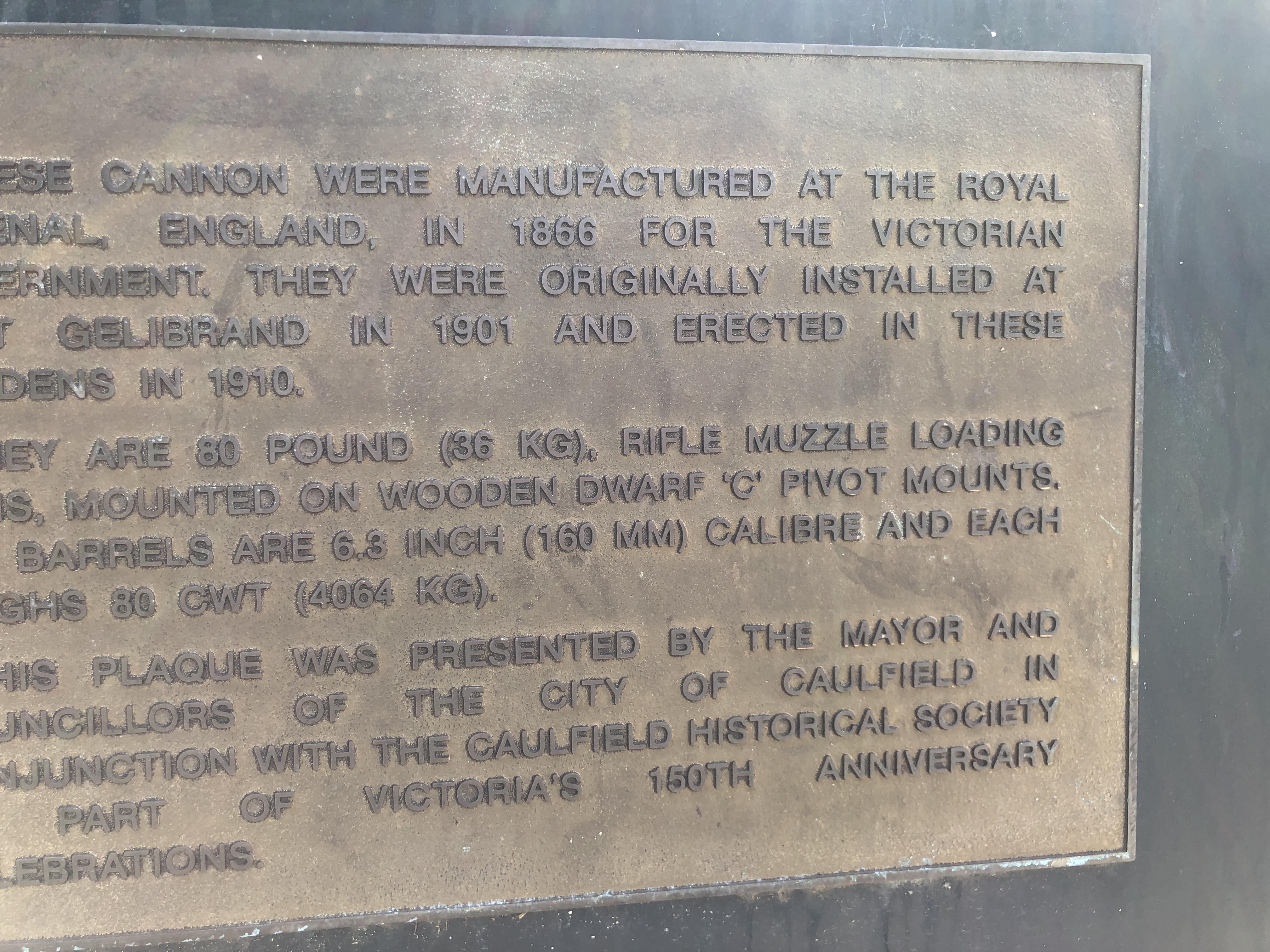
There were only 25 Armstrong 80pd rifled muzzle loaders made, all in 1866. A special order by the Victorian colonial government to the Royal Gun Factory at Woolwich, England. Until today, I had seen and photographed 5 of them. 2 at Warrnambool, 1 at Portland, and 2 at Port Fairy. I believe that there are only 10 still in existence. Today I saw 2 more. These are in the Hopetoun Gardens, in Elsternwick, Melbourne. They are on wooden slides, and have wooden carriages. The wooden components have been repaired, extensively filled, and re-painted. Some parts are missing, including the quoins (the triangular elevating wedges).
The barrel exteriors are in good condition. The muzzles are blocked, so I could not see the bores.
Here are some photographs.
The lithograph on the left is of a 9″ Armstrong cannon. Centre is the battery at Queenscliffe before the present fort was built. On the right is the monitor Cerberus, with 10″ RML guns. Cerberus was scuttled as a breakwater at Half Moon Bay, Black Rock. Her guns were removed and placed nearby on the seabed, where, as far as I know, they remain.The weight refers to the barrel weight and does not include the chassis or carriage. Fort Gelibrand is at Williamstown, where there was a battery for the defence of Melbourne, consisting of 9 substantial cannons. I also visited Williamstown, and photos of the much larger guns which are still there, will appear in a later post.The Port Fairy 80pd cannons were almost certainly originally mounted on wooden carriages and slides like these, until upgraded ~1877.These carriages and chassis’ appear to be substantially original.Queen Victoria’s cypher on these guns is in good condition and exceptionally clear.
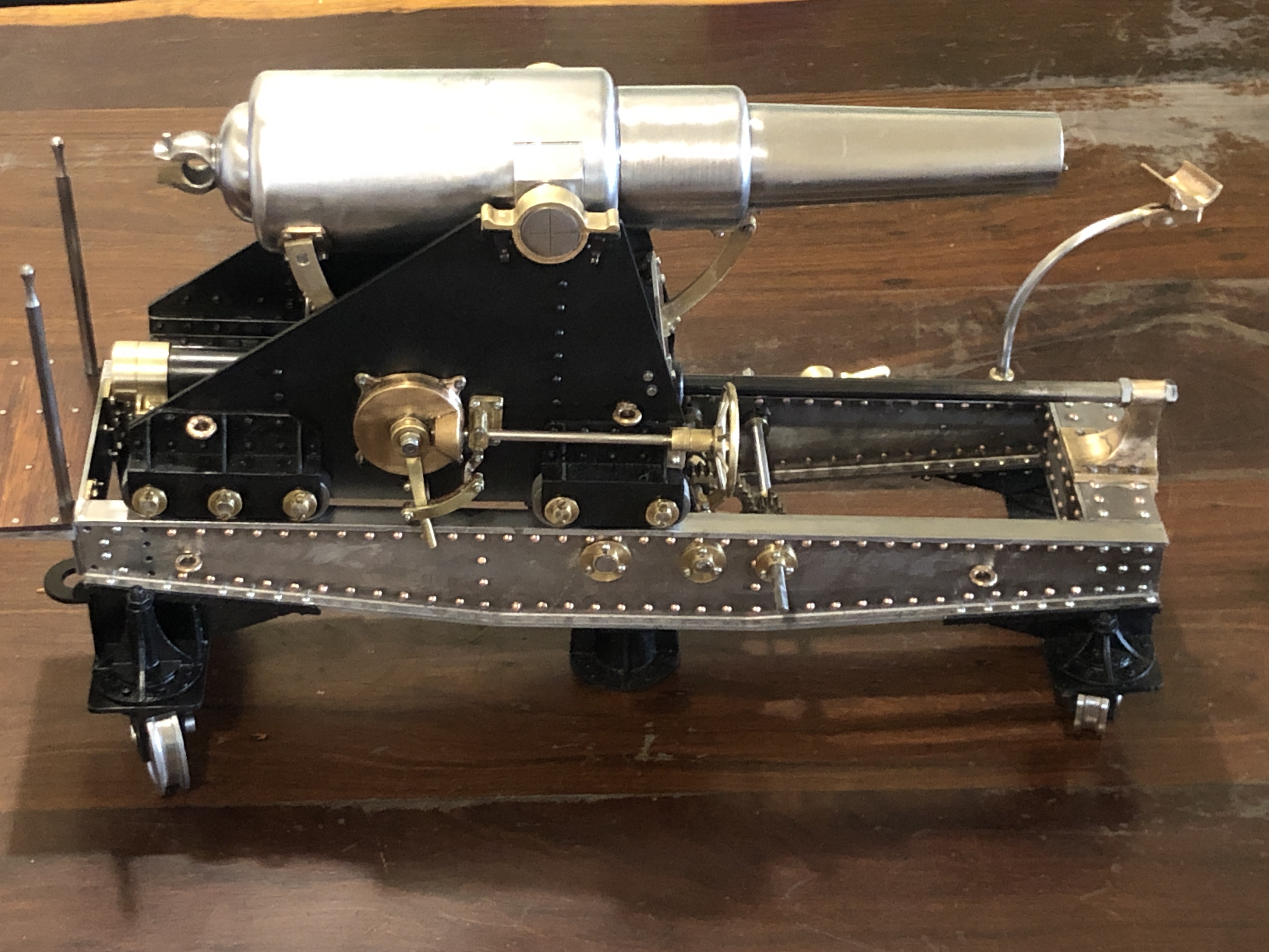
I originally examined the Armstrong 80pd RML cannons at Port Fairy a year ago. Then spent 2020 making a 1:10 scale model. Now, I am completing a second model. Here is a photo of the current status of the 2nd model. And no. There will not be a third.
The components are almost all made, but I estimate that there are many hours required to finish and fit them.
But this post is about my recent 2021 holiday in Port Fairy.
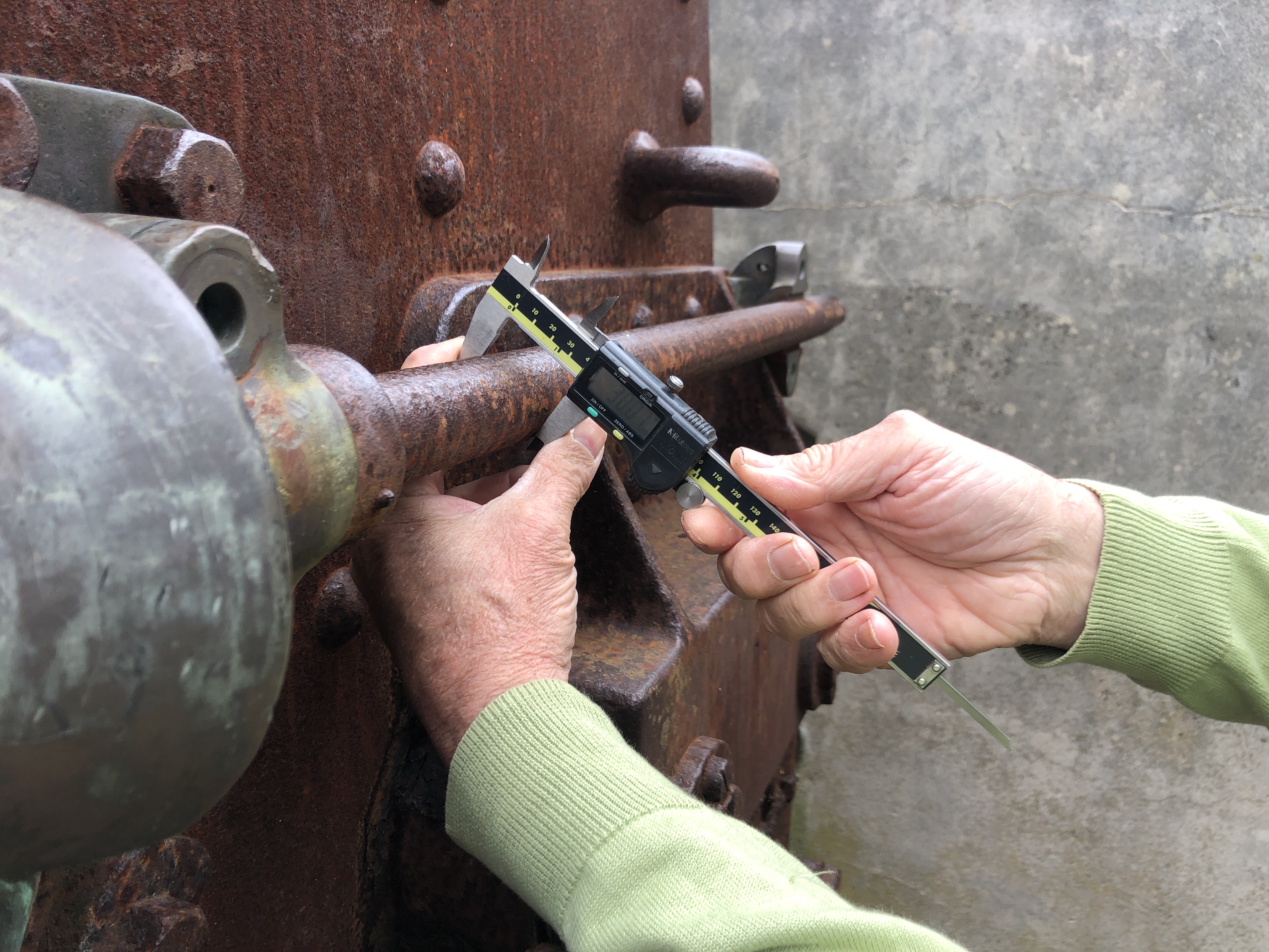
I spent some hours checking and getting more measurements……….
Assisted by my very curious grand daughter “what are you doing Pop?”Who then decided to take over.
My son in law brought his drone to Port Fairy. It is a Mavic 2 Pro with a Hasselbad camera. I was sooo jealous.
And here is his footage of Battery Point. If you look carefully you can see me, my daughter, and Steve controlling the drone. This was a day after the photos above were taken, and my grand daughter was not in the video. Click on the arrow to see the 2″ video.
My daughter was interviewing me again. Amazed at the details being so similar on the real thing compared to the model. My SIL says that the Port Fairy cannons are 10:1 scale examples of my models. Unfortunately the wind noise was too excessive to post her video.
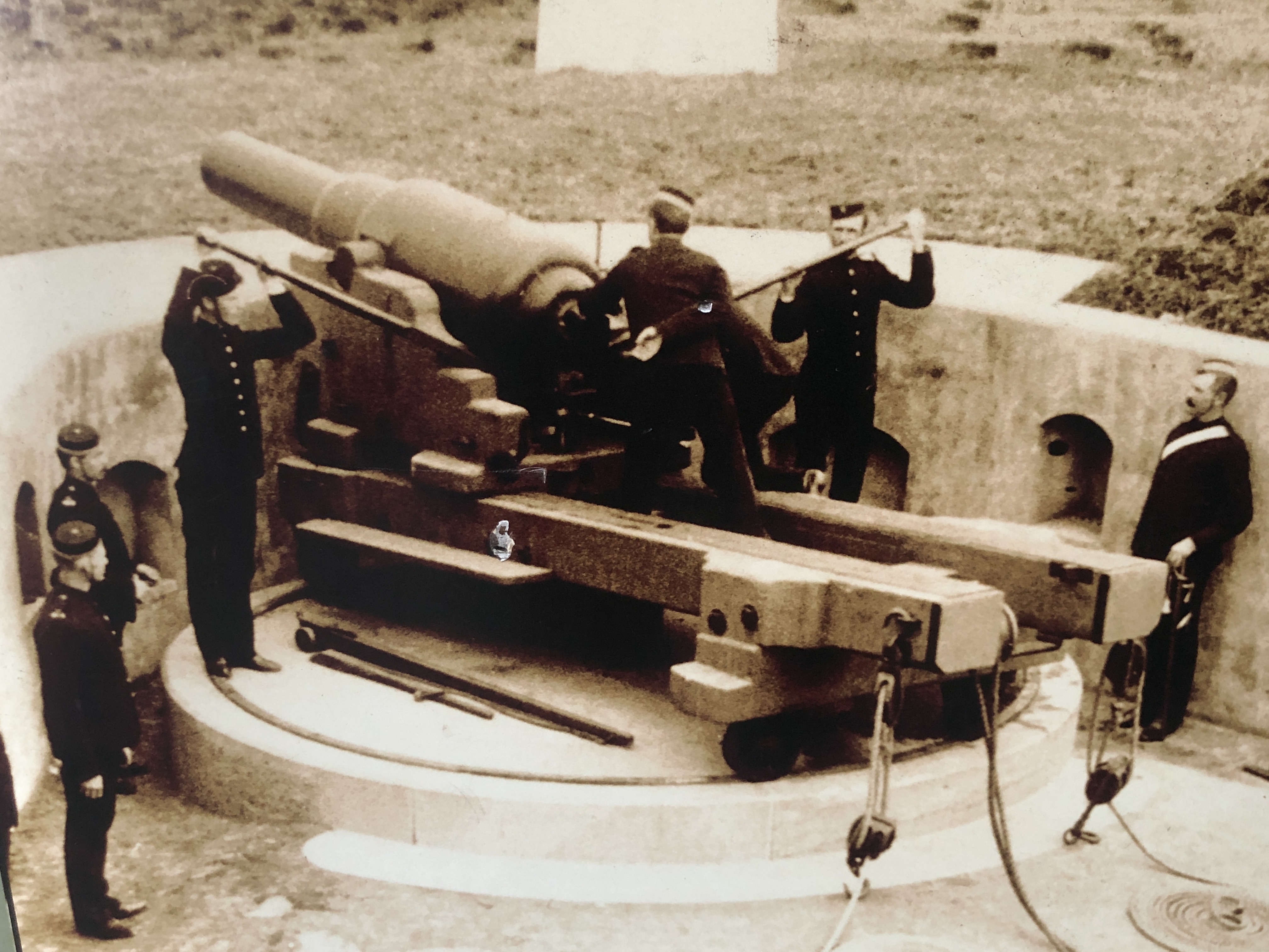
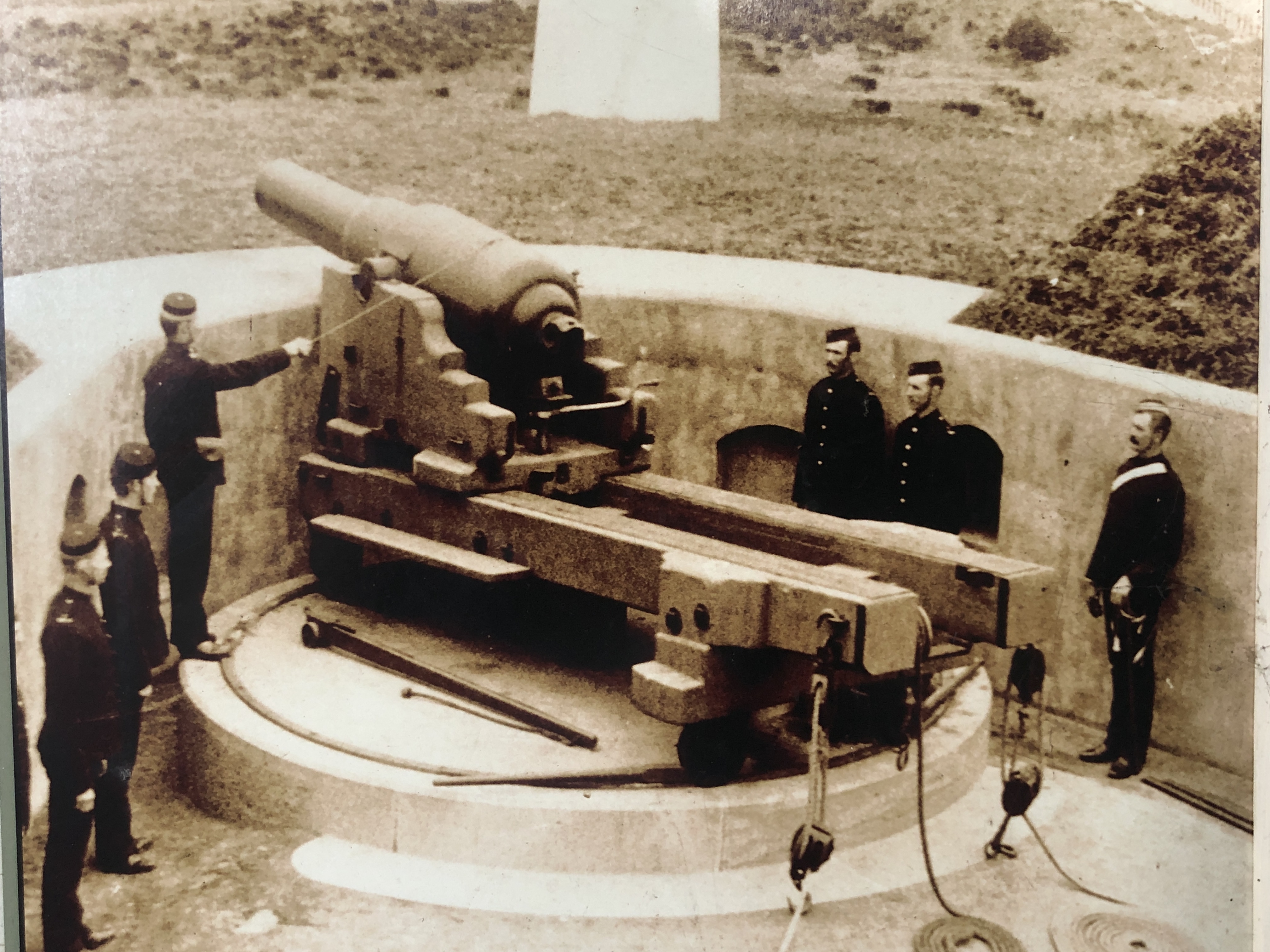
When visiting the Armstrong 80pd RML’s recently at Port Fairy, Portland and Warrnambool, I made sure to take photographs of any old photos which were on display. Some were very interesting.
Portland RML, not dated, but I would guess early 20th century, after decommissioning.Portland RML, probably 1880’s?1880’s Information sign at Portland batteryProbably my favourite. The cannons of the Warrnambool Battery being relocated to Flagstaff Hill 1887. On wooden carriages, and towed by a steam traction engine.The Warrnambool RML on its original wooden chassis & carriage. Adjusting the elevation with crowbars while using the sights. Traversing had been adjusted with the blocks and tackles.Pulling the lanyard to fire. There was a recoil dampener. See next photograph.At Flagstaff Hill Warrnambool there is an 80 pounder on its original teak carriage. I asked to see the recoil dampener which had been removed. 2 staff members very kindly took me into the warehouse where many unrestored items are located. This is the dampener. I guess that the bronze clamps were compressed onto a metal rod to reduce the recoil distance at firing. (nb. Aug 2024. That is incorrect. There was an iron eliptical post separating the bronze split ellipse, which when rotated by a long handle pushed the wooden halves apart. The wooden halves acted as brake shoes, to slow the rate of descent of the carriage/barrel down the slide to the firing position. According to an 1874 book titled Treatise on Military Carriages, the brake was mainly used to limit the recoil on firing.) I have searched the Internet for pictures or other evidence of the wooden braking system, but this is the only one that I could discover. When not in use, the wooden brake was normally removed and stored under cover, along with sights, and other removeable parts. It is amazing that this one was found, albeit dilapidated ON an old, relatively intact gun. I made several model guns which used this system. See later posts.)Externally the 64 pounder was the same as the 80 pounder. On its original teak chassis. There are several original chasses still in existence at Flagstaff Hill, Warnambool and Hopetoun Gardens, Elsternwick. One of the slides at Warnambool is badly rotted, exposing the otherwise hidden iron fittings within.
10 members of my family had a brief vacation in South West Victoria after Christmas. It was a nice holiday, but with three 5 year olds and an 8 year old, it was noisy.
I took the opportunity to revisit the Armstrong RML’s at Port Fairy and Warrnambool. And to visit the one at Portland for the first time.
Every time I see these cannons I learn something new about them. And I got to talk to a local historian at Port Fairy. Colonial Victoria purchased 25 or 26 of these muzzle loading rifled cannons in 1866. 10 of them are still in existence. I have now seen 5 of them. I believe that there are further barrels at Fort Queenscliff, Point Nepean, and possibly Cerberus which I have not yet seen.
“80pr” indicates that the cannons fired projectiles weighing 80 pounds. On all of these cannons the case of the elevating gears is stamped thus….
I am not sure what M2 GAR. stands for. Could it be an abbreviation of Mr WG Armstrong (later Lord Armstrong), the designer of these guns? (note 27 Jan 21. I spoke at length with Australian cannon expert Peter Webster. He said that GAR stands for “Garrison”. Not sure why, but maybe to distinguish it from naval guns.) R.M.L. will stand for “Rifled Muzzle Loader”. 80 PR will be 80 pound projectile. 6 FT PAR had me puzzled, but when I saw that the guns were designed to sit behind a 6 foot parapet I am pretty sure that will be the solution. And in a smaller font below, WD with a vertical arrow will indicate that the part has been approved by the War Department.
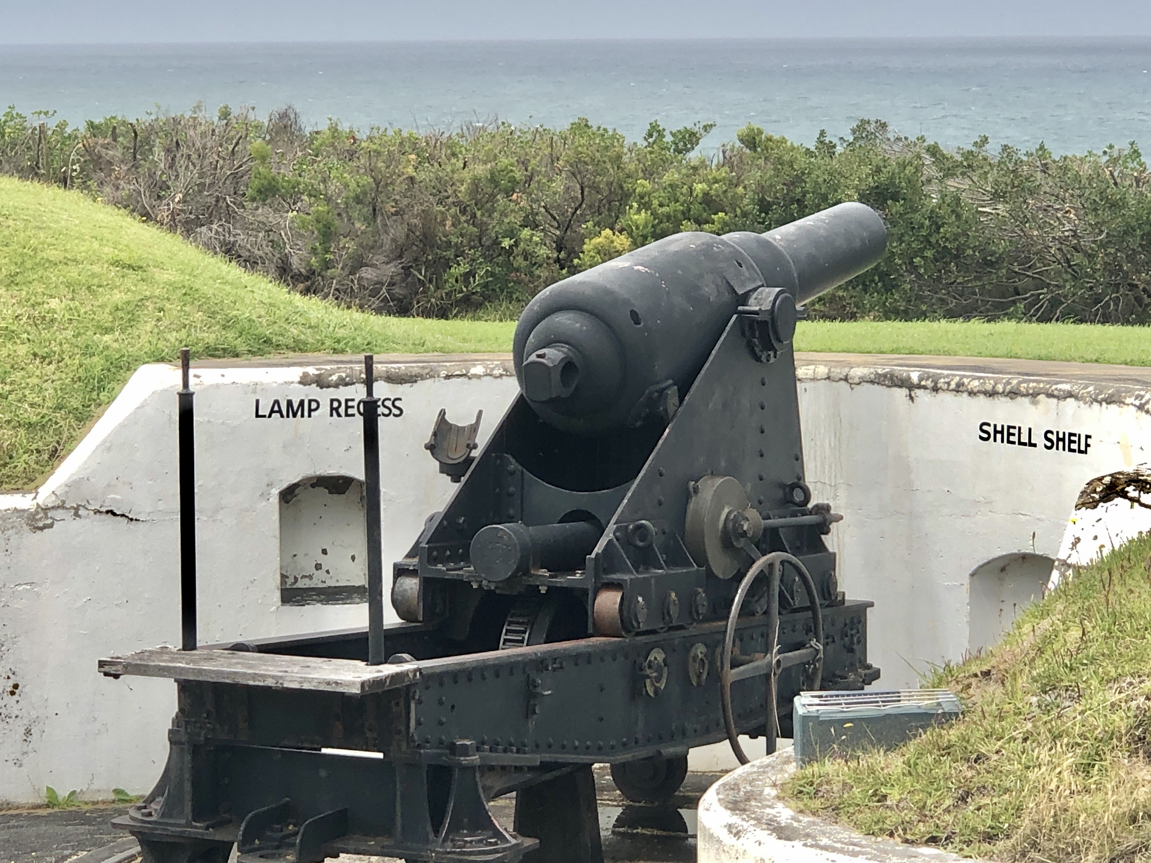
The Portland 80pr RML
From a distance, it looks good. The shapes in the carriage and chassis stand out with the white paint, and the assembly looks reasonably complete, except for absent winding handles and sights. Closer inspection however is disappointing. The cannon was restored in 1985 and the parts which were replaced such as the biggest gear, the elevation quadrant scale and trunnion caps, and elevation gear are significantly different from the originals on the Port Fairy and Warrnambool cannons. They appear to have been cut from mild steel in a fanciful representation of the original designs. Arc welding has been extensively used to join components. It is OK as a tourist attraction, but useless for historic study.
And instead of pointing over Portland Bay, it points at the large grain silo.
PORT FAIRY CANNONS REVISITED
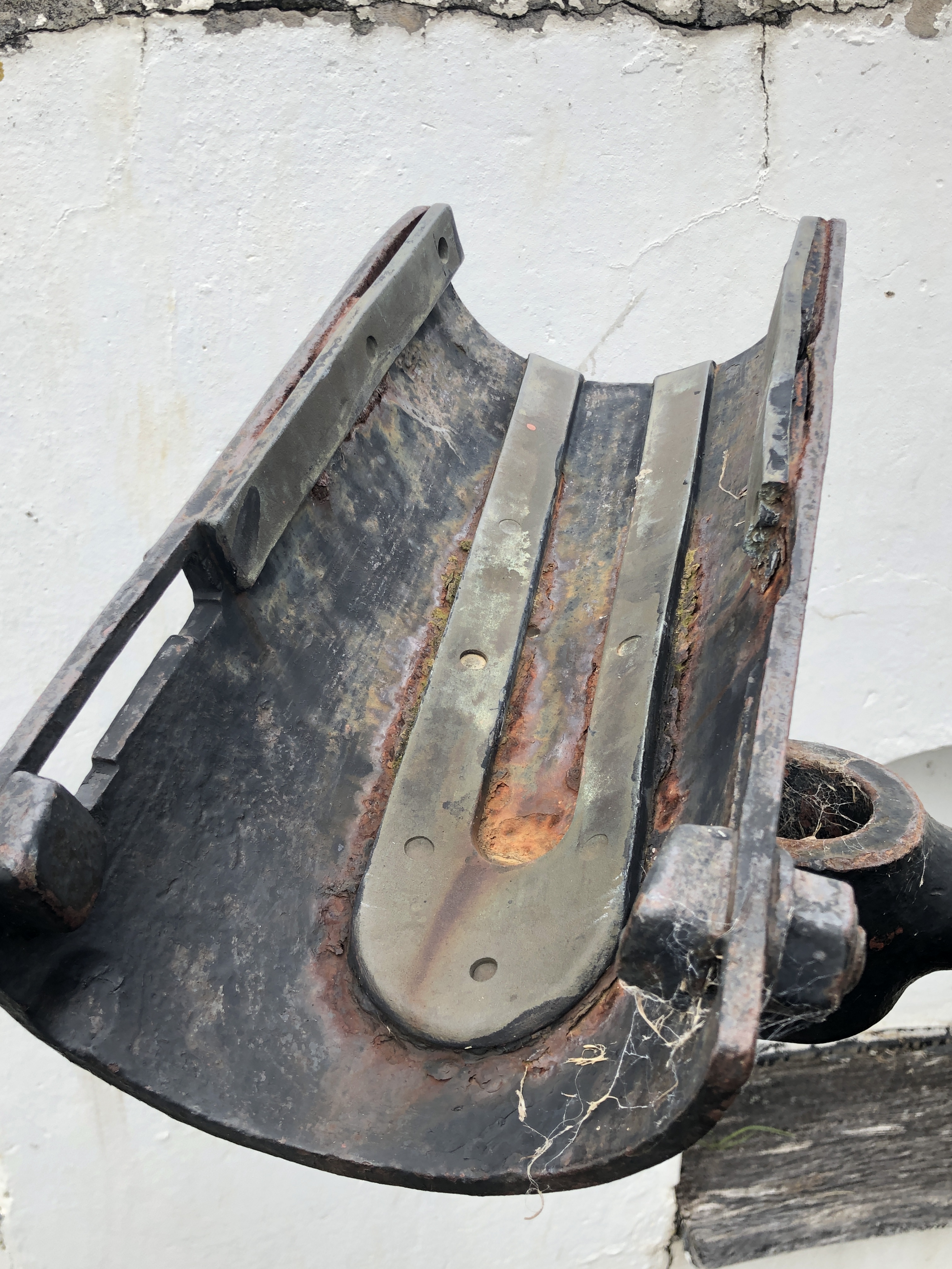
Overdue for restoration works, the carriage wheels are largely crumbling into rust, and the girders have large rusted missing sections. The barrel of number 22 is elevated to a high angle which would never have been used, but is useful for firing blank charges for the entertainment of tourists, and which I enjoyed 12 months ago. Number 17 barrel rests on its parapet, at such a low angle that it too would never have used. The total lack of restoration does allow one aspect of the barrels to be visible, and that is the coil construction of the barrel segments.
Number 22Close up of the breech steel. Pitted and rusted. Can you see the spiral strips of iron which were bent and hammered as red hot strips up to 200 feet long, around a mandrel?
I measured the widths of the strips, and found that those on the narrowest part of the barrel (the chase, near the muzzle) were the narrowest at 36mm, and those of the biggest barrel diameter, the breech, were 50mm wide.
As a comparison to the previous photo of a coil constructed barrel, this similarly rusted 1861 SBML (smooth bore muzzle loader) shows no evidence of the spiral iron strips, and would have been a cast iron construction with machine bored bore.
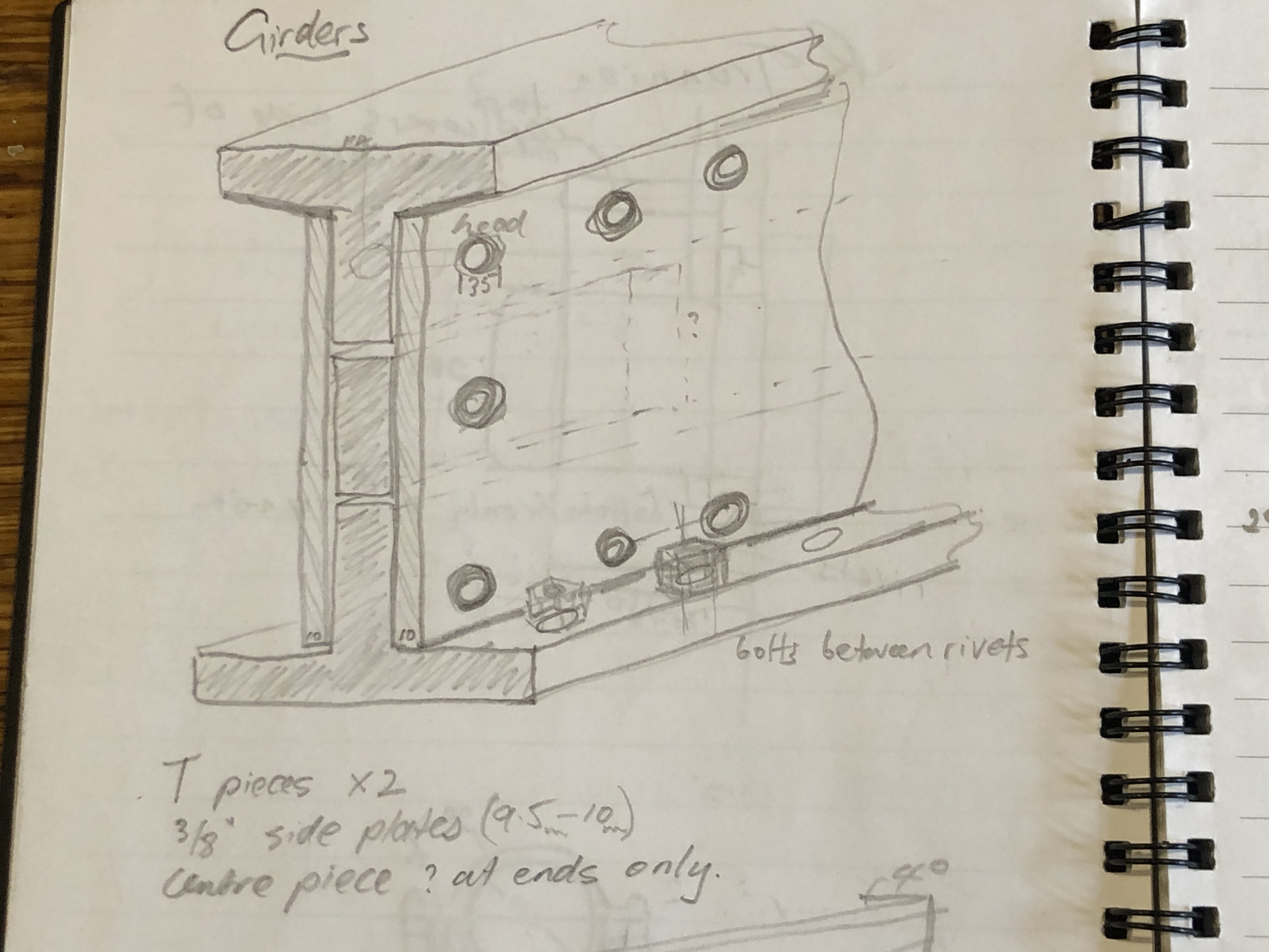
I was also able to work out the structure of the girders on the Armstrong RML, and the reason for all of those rivets. The top and bottom pieces are T section iron, and the sides are 3/8″ (9.5mm) plate iron. There are small pieces of iron to fill the gaps at the ends, and where intermediate rivets are used in the middle sections. Using a percussion technique, taught to all medical students for diagnosing pneumonia, I could work out the locations of all of the small middle pieces.
The girder end, showing the T pieces, side panels and middle filler piece.My sketch of the construction of the girders.Another family member being introduced to the Port Fairy RML cannon, probably as a fashion accessory.
WARRNAMBOOL ARMSTRONG RML’s
These have been expertly restored, and are the most complete examples which I have seen. They were painted entirely black which makes photographs more difficult to interpret.
Whales are commonly seen in the bay. Unfortunately none on this day.
This is a close up of the projectile loading cradle. The deep groove at 6 o’clock caused me to re-examine the history of studded projectiles and non studded gas check projectiles. Apparently the studded type were used until the mid 1880’s but were discontinued when gas checks were introduced. Gas checks were effective and caused less bore erosion wear than the studded type. The groove at 6 o’clock would have accommodated the lowermost stud. The cradle would have continued to be used with the gas check projectiles.
Next post will include some interesting historical photos, and other restored cannons which were recently installed at Port Fairy.
1:10 Model Armstrong rifled muzzle loading 80lb cannon WILL be ready for Xmas.
Apart from minor touch-ups, the model and painting is completed.
I will take some careful photos before it goes to its final home, but here are a few snaps to show how it appears with some paint and lacquer.
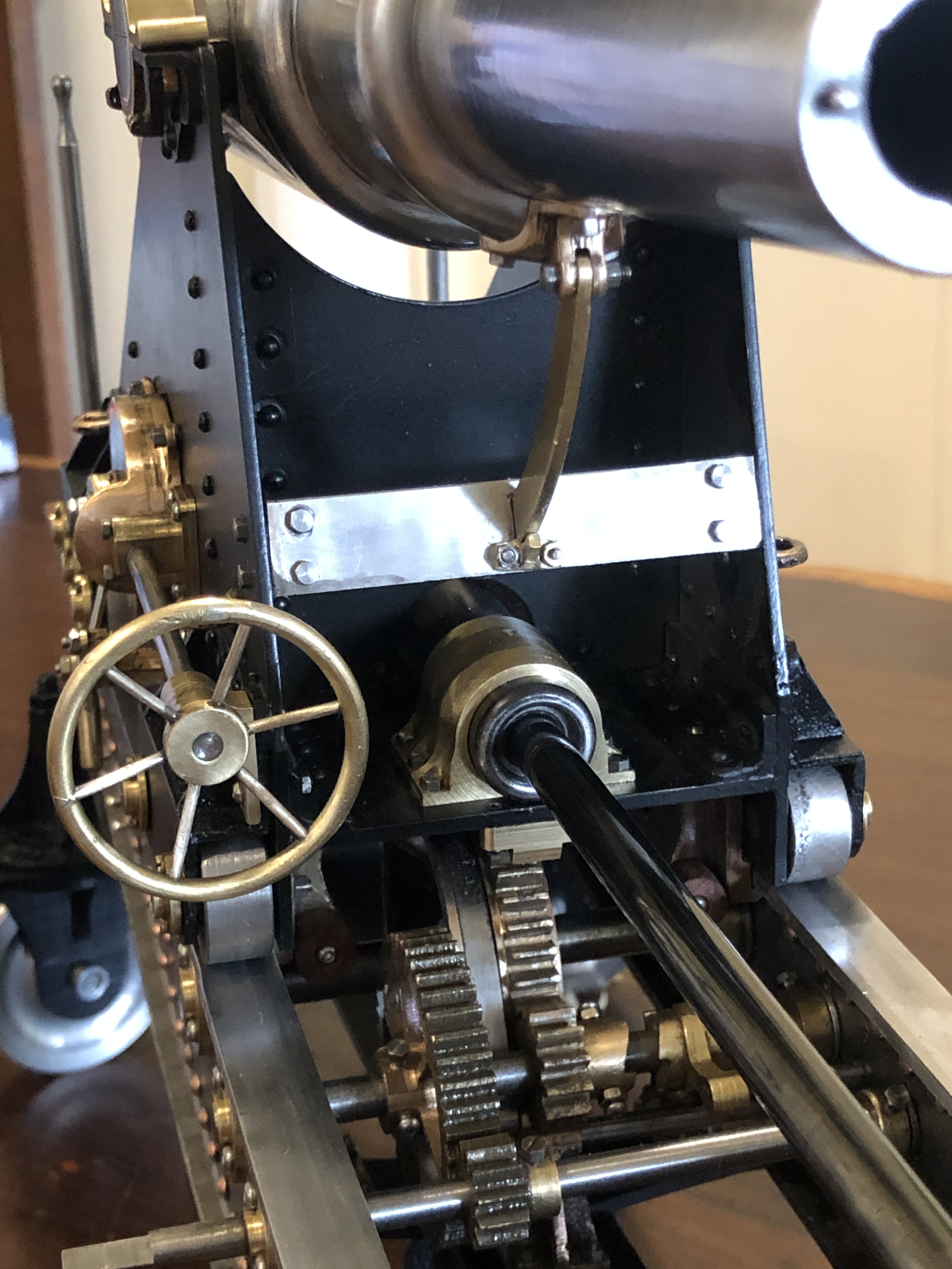
Oops. Forgot the big handwheel.The gears, brake and dog clutch all work well.and a few more chassis bolts to insert.I extended the recoil piston rod to allow full travel of the carriage on the chassis. The join is smooth.
So, was SWMBO correct about not painting the chassis? I like the look of this finish scheme, but now have to decide what to do in that regard with the “A” model, which was put aside while I finished this one.
p.s. I weighed the model, because I was curious. The full size original barrel weighed 81.5cwt/4.1 tons plus the carriage/chassis, about 5 tons/5080kg total. The 1:10 scale model should weigh 0.1 x 0.1 x 0.1 or 1/1000th of that which would be 5kg/11lbs. It actually weighs a tad under 10kg/22lbs which is almost exactly double the predicted. It is a bit of a lump to carry around and I do NOT know where the extra weight came from. Or maybe my mathematical assumptions are incorrect.
(note added 1 March 2021. See the post added 1 March 2021. The total weight of the gun barrel, carriage, and slide – which I have been calling the chassis, was close to 10 tons! So my assumption that the model should weigh 1/1000th of the original was very close to correct!)
First, I have decided to NOT rivet the final joins of the chassis. Instead I am using dome head stainless steel bolts and nuts. The main reason is that the other end of the rivets are in impossibly small (for me) cavities and spaces, and I could predict that the final riveting result would be horrible. Even using threaded rivets would be incredibly difficult. This decision does cause me to reflect on the 1866 cannon builders who managed such perfect results with red hot rivets in confined spaces, and again, to be awed.
As you can see, the bolt heads are same shape and size as the 2mm copper rivets. My intention was to paint the rivets and the bolts (after filling the hex holes) and then they would be virtually indistinguishable. However, that plan was blown out of the water by SWMBO. (read on).The copper rivets and stainless bolts. Not kosher. But interesting?
To divert, back to the painting.
Question. When painting a model, is it best to assemble the whole model then paint, or to completely disassemble every part, paint the parts then reassemble?
1. Disassemble and paint the parts then reassemble. This results in complete paint coverage of all parts. It results in clean separation of different coloured parts. Mistakes involve limited areas and are easier to correct. However, the thickness of the paint can alter carefully machined tolerances. And surfaces can be painted which were intended to be unpainted.
2. Assemble the entire model, then paint. This can make some recesses, corners and hidden areas difficult to access. But the appearance of the entire model can be assessed as the painting progresses, and major mistakes in colour choice can be corrected. The painting process does not alter dimensions or fitting together of components. But paint edges and joins can be difficult to keep neat and straight, particularly in my inexpert hands.
3. (Obviously what I chose to do). Partial assembly, into modules, then paint the modules separately. This has the advantages of both 1 and 2. The modules can be stacked together to periodically assess the results. The modules are smaller than the complete model, and easier to handle. Difficult decisions regarding colour, or whether to paint at all, can be deferred until the easier parts are painted, and some idea of appearance ascertained progressively.
So that is what I am doing. I have painted the bottom part of the chassis, and the carriage. Etch primer at this time, but already firming up ideas about final colour. And my colour and design expert advisor (SWMBO) has had some input into this decision.
These are the main modules, 4 of them. The barrel assembly is stainless steel and it will not be painted. At the rear are the carriage and bottom part of the chassis, which have been primed. The main chassis beams containing the movement gears are unpainted. The carriage looks naked without its bling.
At this stage, I asked for advice from SWMBO. She has suggested that the primed modules should be painted satin black, which should contrast nicely with the brass/bronze components. Avoiding gloss will minimise the finishing defects. Some filling of defects will be required in any case. The black colour will be tested on the carriage, and if it looks OK, the chassis subframe will receive the same colour.
SWMBO’s most interesting suggestion is to NOT paint the main chassis beams at all! Well, a clear lacquer will be required to prevent rust.
But. What about disguising the copper rivets/stainless bolts?
SWMBO: “they look interesting. Leave them.”
Me: “but, but, but, they do not look authentic.”
SWMBO: “This has to look like a work of art, otherwise it will be just a boring dust gatherer.”
Today the gunners’ platform at the rear of the chassis was completed and fitted. It has vertical handles at each side, presumably for the gunners to steady themselves, while aiming the cannon.
The platform, ready to be attached to the chassis. The wood here is Australian Jarrah. The handles are stainless steel, discoloured from silver soldering them to the side brackets. They will eventually be painted. ps. a day later I decided that the fasteners were too big, so I have replaced them with something more appropriate. Pics later.The platform in position. This photo shows up my first efforts at riveting. Some of those rivets will be replaced when everything is disassembled prior to painting. Those brass nuts holding the wooden boards are too big and will be replaced also.
So, just 2 more parts to be made for this model cannon. Those are the sights.
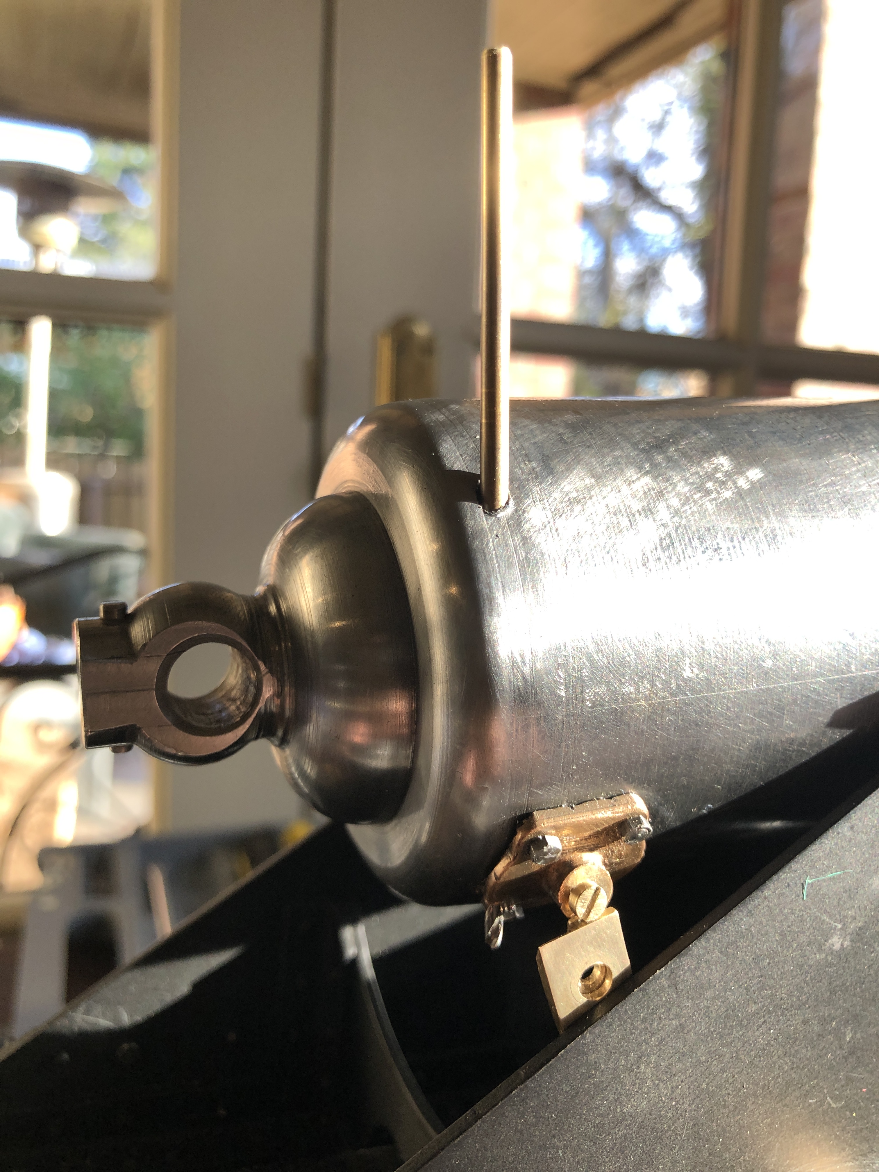
The information which I have to base the sights on is a bit sketchy. But I do have photos showing these cylindrical holes in the Port Fairy cannons….
The sights are placed in the holes in the right hand trunnion shoulder, and in the breech.
After extensive searching I found several books which were published in the 19th century. This is the best diagram which I found of the rear sight. It is calibrated vertically up to 3600 yards, and there are lateral adjustments to take into account speed of movement of the enemy. The sight is angled at 2+º to the left to compensate for the rifling, which causes the projectile to deviate to the right. The front sight is located in a relatively shallow cylindrical hole. The front sight is a fairly simple point.
It took a whole day making and fitting the top caps of the trunnion mounts from brass.
A 76 x 76mm piece of brass was milled to 10mm thickness. The trunnion straps will finish at 9.5mm , giving me a 0.5mm machining allowance.
The 4 straps were cut out using a new 4mm endmill. Rounded internal corners were milled square, and the bottom tabs were milled to 2mm thickness.
2mm wide slots were milled into the brackets, and ends of the slots were filed square. None of my rifling files were small enough, so I ground one to size, leaving the faces and one edge intact.
Trunnion mount almost finished. Pins in the tags to come, and they will pull the strap down tight with a cam action. The half circle line on the bottom bearing is a painting border to delineate the bottom bracket from the bronze bearing surface which will not be painted. If you inspect the full size trunnion in the previous post you will see what I mean.
Now I can take some measurements of the model, and start the barrel elevating gear. There are 4 gears to be cut, including bevel gears, handle, shafts, gear case, and some complex mounts.
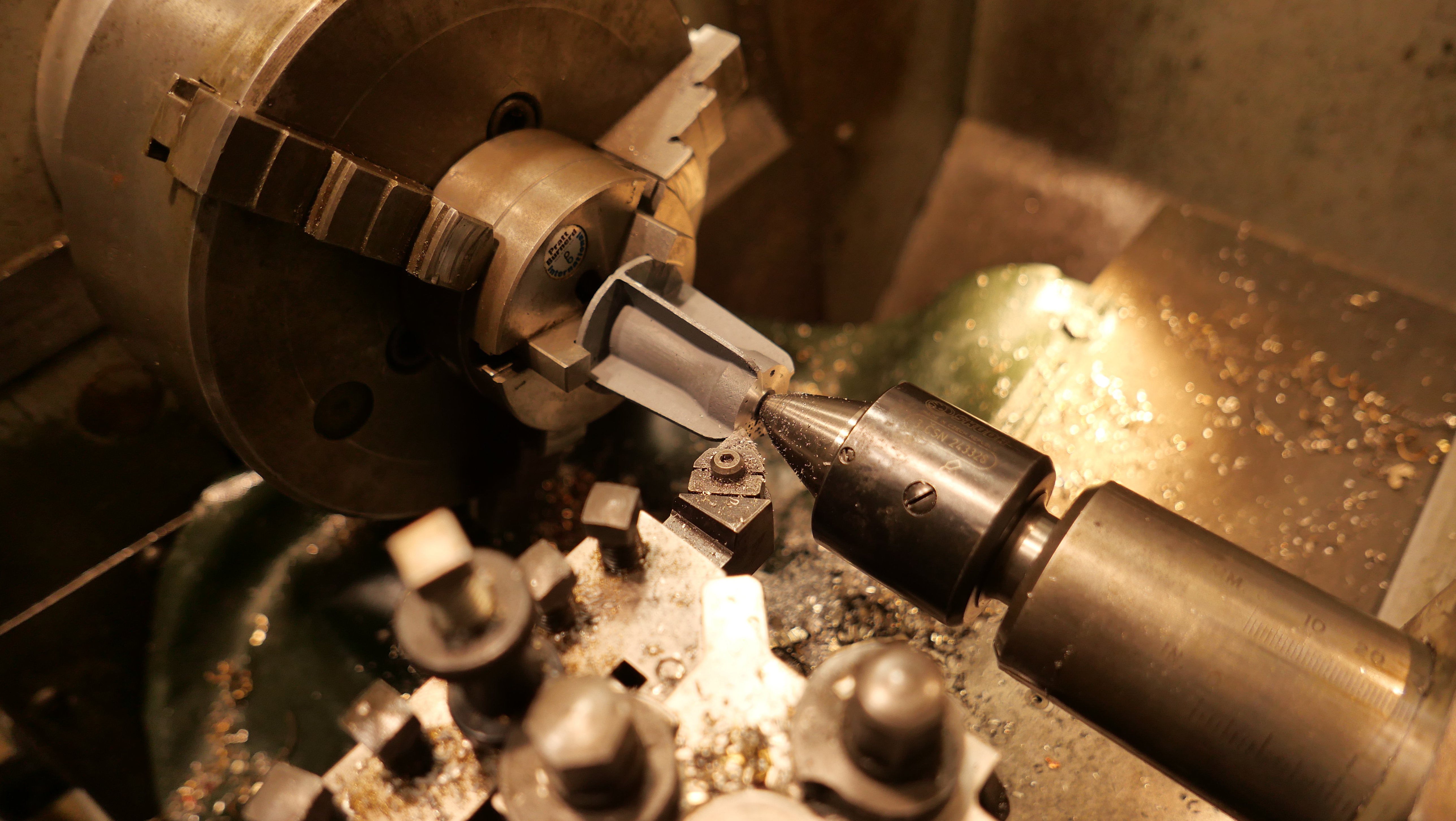
I needed to machine some of the aluminium castings which I had made for the cannon chassis. They were too high by 1-2mm. But, the flanges were delicate and thin walled, and although the ends were flat and roughly parallel, they were not actually parallel. I wanted to use my most rigid and precise lathe, which is the Colchester Master 2500. But the bore on the chuck was greater than the diameter of the part which I was turning.
So this is the setup. A chuck in a chuck.
The Colchester 3 jaw is 200mm diameter, and it neatly holds a 80mm chuck off my Boxford TCL125 CNC lathe, which holds the part. It is a centre column from the scale model Armstrong gun which I am currently assembling/making. It is a bit irregular, with thin 2mm flanges and fins. I really did not want to damage it, but it needed 1-2mm trimmed from its height.
So, I held the part in the 80mm 3 jaw, centre drilled it, and supported it in the 3 jaw and the tailstock. It worked well. No disasters.
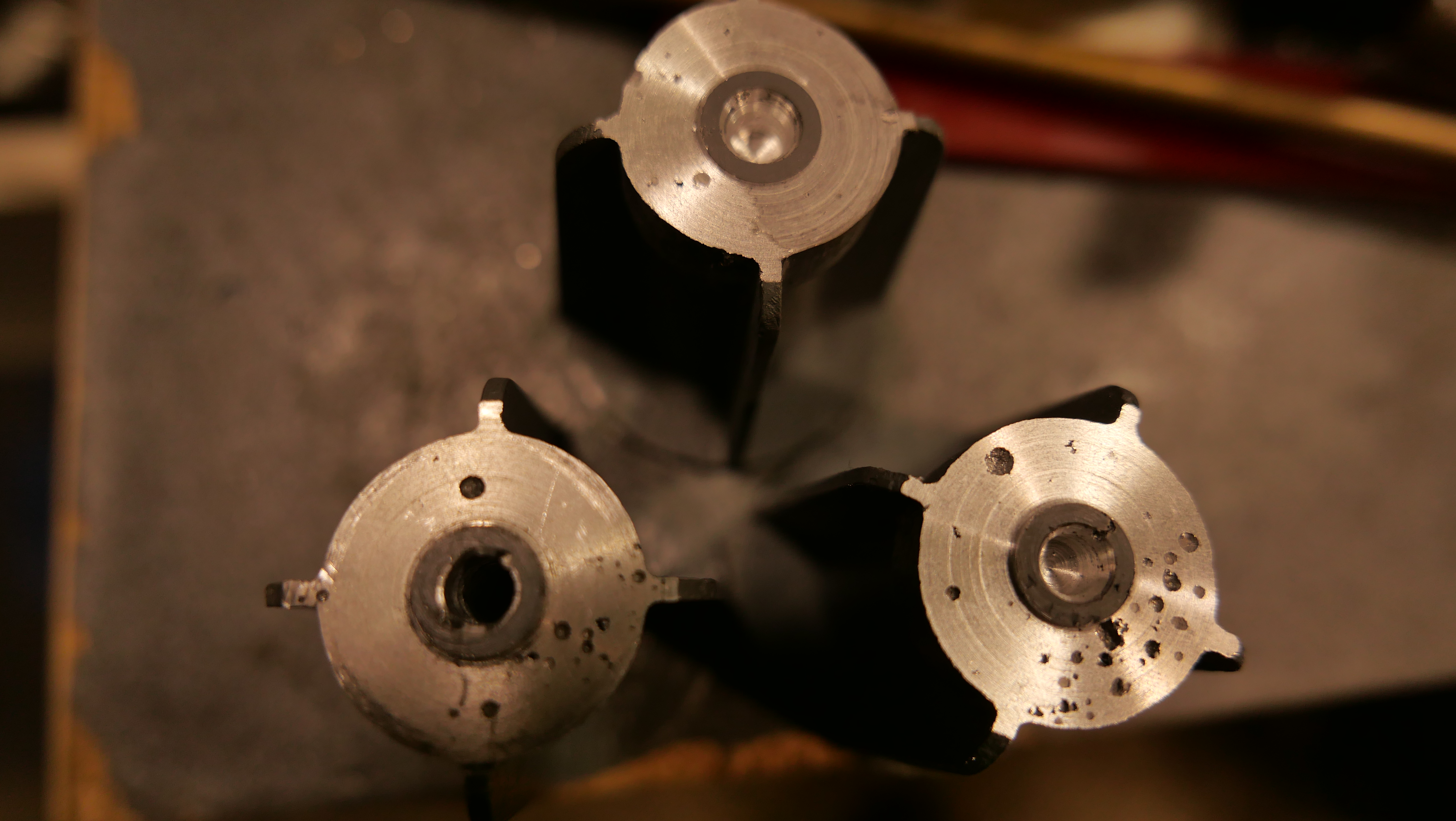
I machined the three castings which I had made. And reversed them to machine the bases. The setup worked well. I need only 2 of these, and could use any of them. The machining did reveal some porosity of the castings, but overall I am quite pleased with the end result.
p.s. You might notice some advertisements in my posts from now on. Unfortunately I am at my storage limit on my current WordPress plan, despite deleting virtually all embedded videos, and placing the main ones on YouTube. I am facing the prospect of either deleting old posts, or increasing my WordPress payment plan to a business plan, which is substantially more expensive. I have decided to see if monetising the site will cover the cost of upgrading to a business plan. I do hope that the ads will not be too intrusive. Let me know what you think.
The assembly of my Armstrong cannon is progressing more slowly than I anticipated. No excuses. Just lots of holes to drill in precise positions, parts to turn and mill. And my workshop sessions have become shorter in the winter cold. Not that I mind the cold. I just light my workshop wood fire to remove the chill.
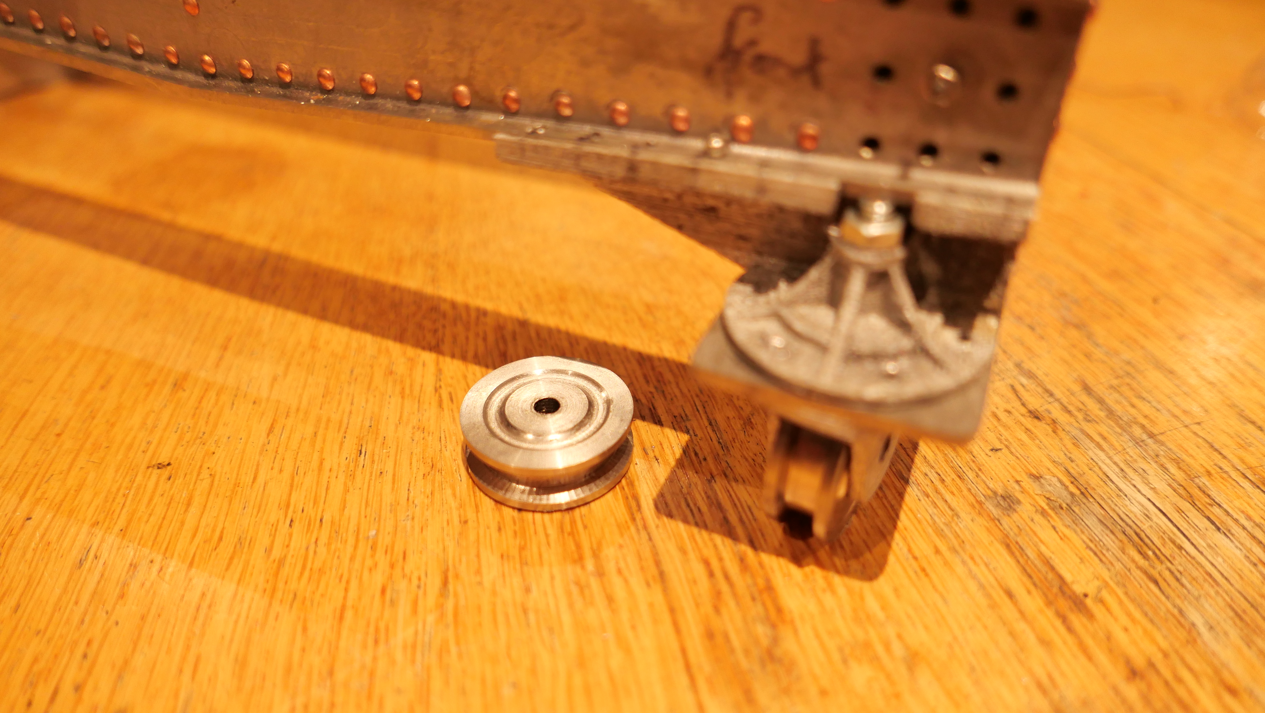
Today I have been making the wheels for the chassis.
Not a great photo. It shows a front wheel, 33mm diameter, turned from stainless steel. No axle yet.
And a rear wheel, 50mm diameter. Yet to have the track groove turned into the periphery.
I thought that the wheels would be easy to make. Just a bit of basic turning to size and form turning for the track groove and decorative relief on the faces. But as usual, I used whatever material I had on hand in the size. In this case stainless steel. It looks great when turned, but does work harden quickly, causing tooling problems. Parting off, through 50mm of hardened stainless steel is not much fun. In the end I used the band saw for parting, then tidied up the ends on the lathe.
For some reason which I do not really understand, my youngest daughter has become interested in my metal casting activities.
First she watched me do a molten aluminium pour.
Then she rang me a day or two later and asked if she could have a go. She really wanted to do it in brass or bronze, but as a relative beginner myself, and with only one episode of molten brass, and that one did not go so well, I demurred, and said that her first effort would have to be in aluminium.
So I prepared 3 flasks, printing the plastic parts, and gluing them into a wax tree, then slowly heating the flasks in the potters oven, up to 750ºc over 8 hours. Then lowered the oven temperature to the pouring temp of 710ºc. And preparing the aluminium melt at 710ºc.
When Eleanor arrived, we had a couple of practice runs with flasks full of sand, so she could get used to the weights and handling the tongs, and the various movements while wearing the protective gear.
Then the pour. This is Eleanor’s video of the event.
I admit to some substantial reservations about this exercise, but Eleanor listens carefully, asks intelligent penetrating questions, and follows instructions precisely. Full marks.
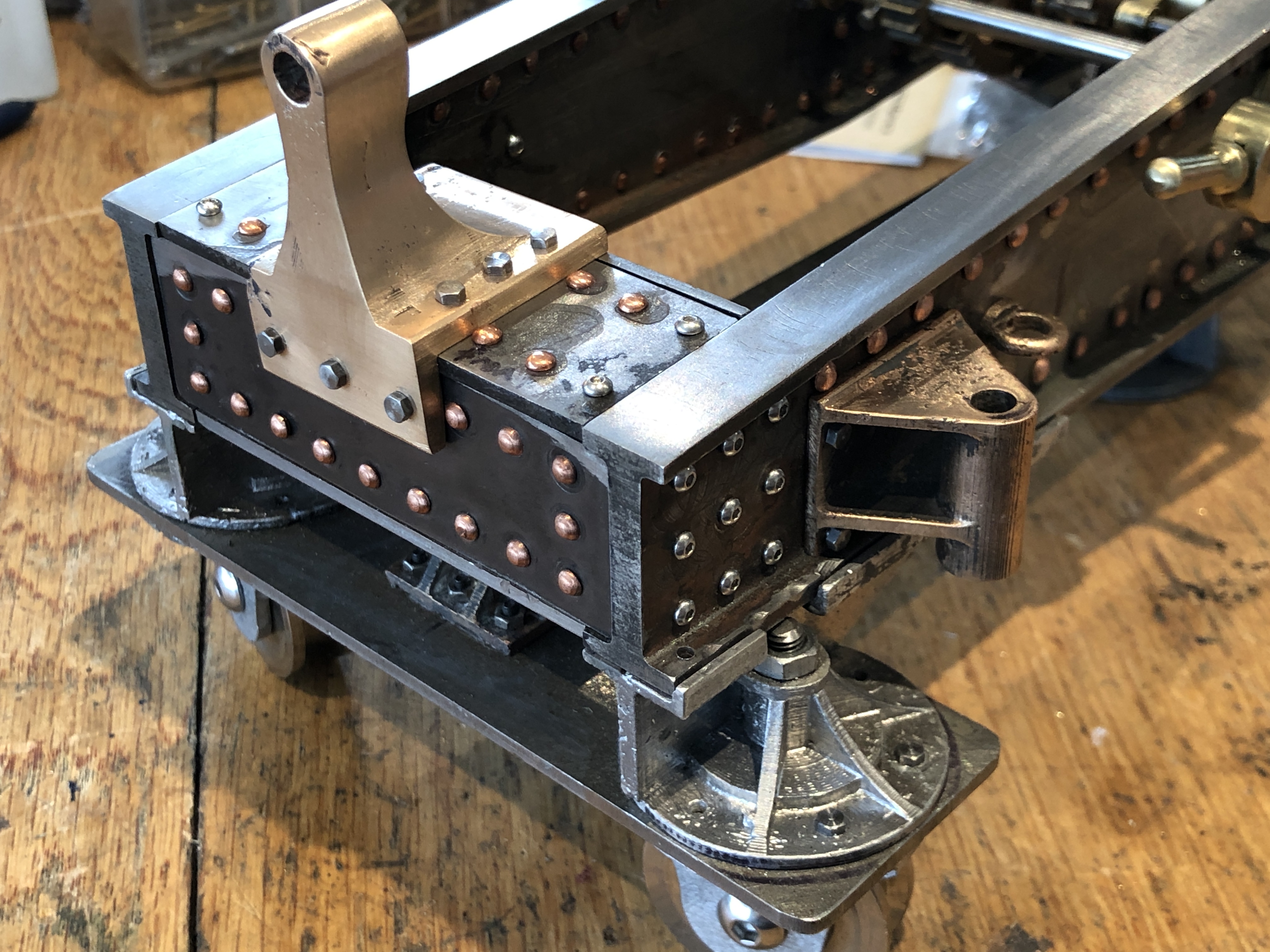
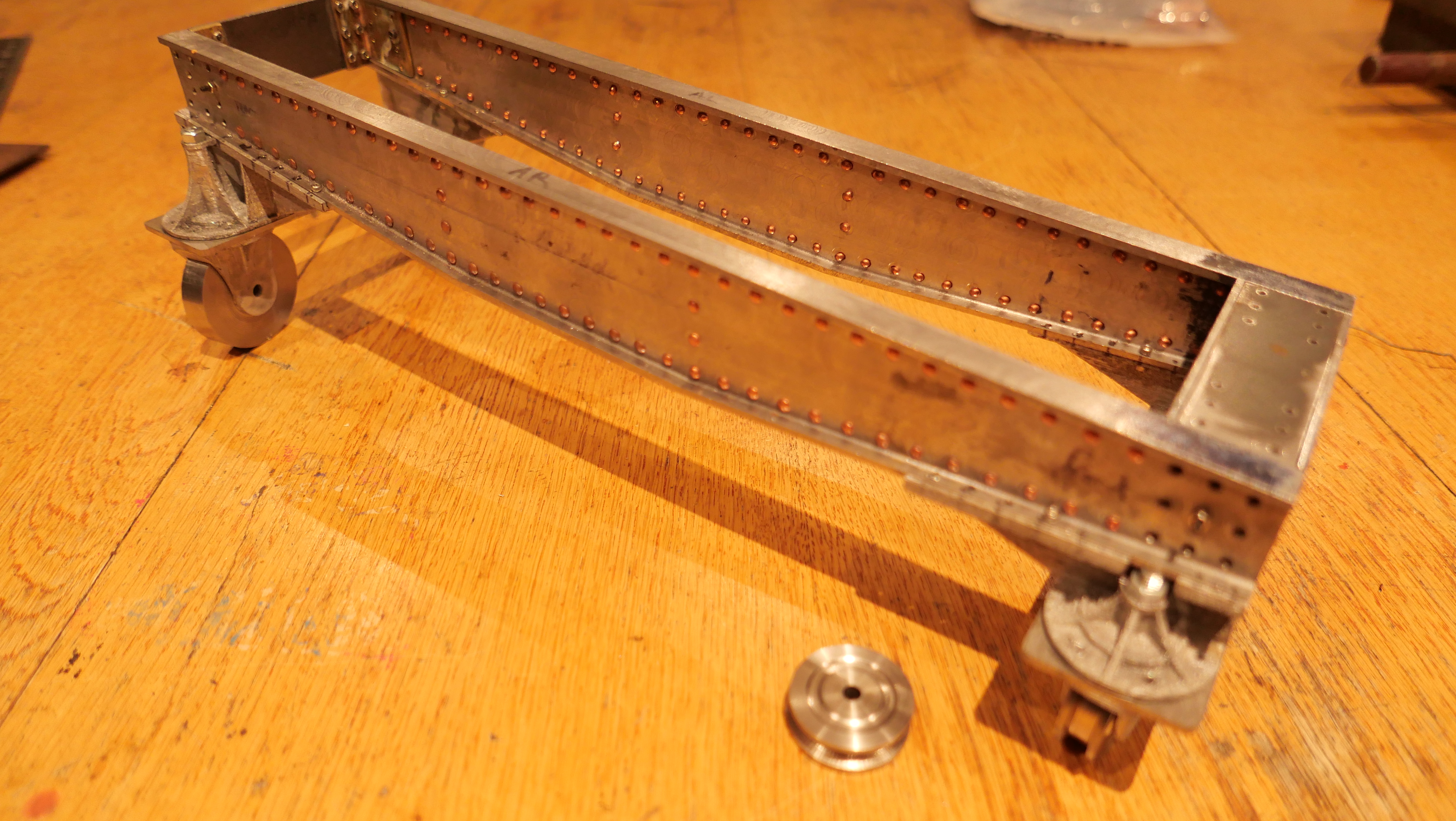
The strength and resistance to twisting and other movements of the Armstrong cannon is in the chassis. Specifically the design and strength of the longitudinal girders, AND the box section structure at the front of the chassis.
The box section has been a challenge in the 1:10 model. Actually, it has been a bit of a nightmare.
It has taken me 3 full day sessions to work out how to construct this assembly, to make the parts, to join them together, then a lot of filing to make the assembly fit the girders.
And, of course, the parts are riveted together, and I am a total novice at riveting.
So this is the result. Not totally finished and assembled, but getting there.
Again, I left my camera at the workshop. These are photos which I took with my phone.
The box section is an assembly of parts. The ends were silver soldered. The panels which show are steel, and will all eventually be riveted to the end sections. At this time, some joins are still just bolted and nutted.
This is the front of the chassis. The rivets look OK yes?
And the inside rivets were the first ones to be inserted. Mostly worked OK. They are copper, will eventually be painted the same colour as the girders.
And after the riveting, I have spent almost a full day of gentle and progressive filing to make the box section fit the girders. It all fitted beforehand. But after riveting, nothing fitted. All of that hammering clearly changed some of the dimensions. But, despite all of my pessimism, it all eventually fitted.
Now, I have another chassis to make.
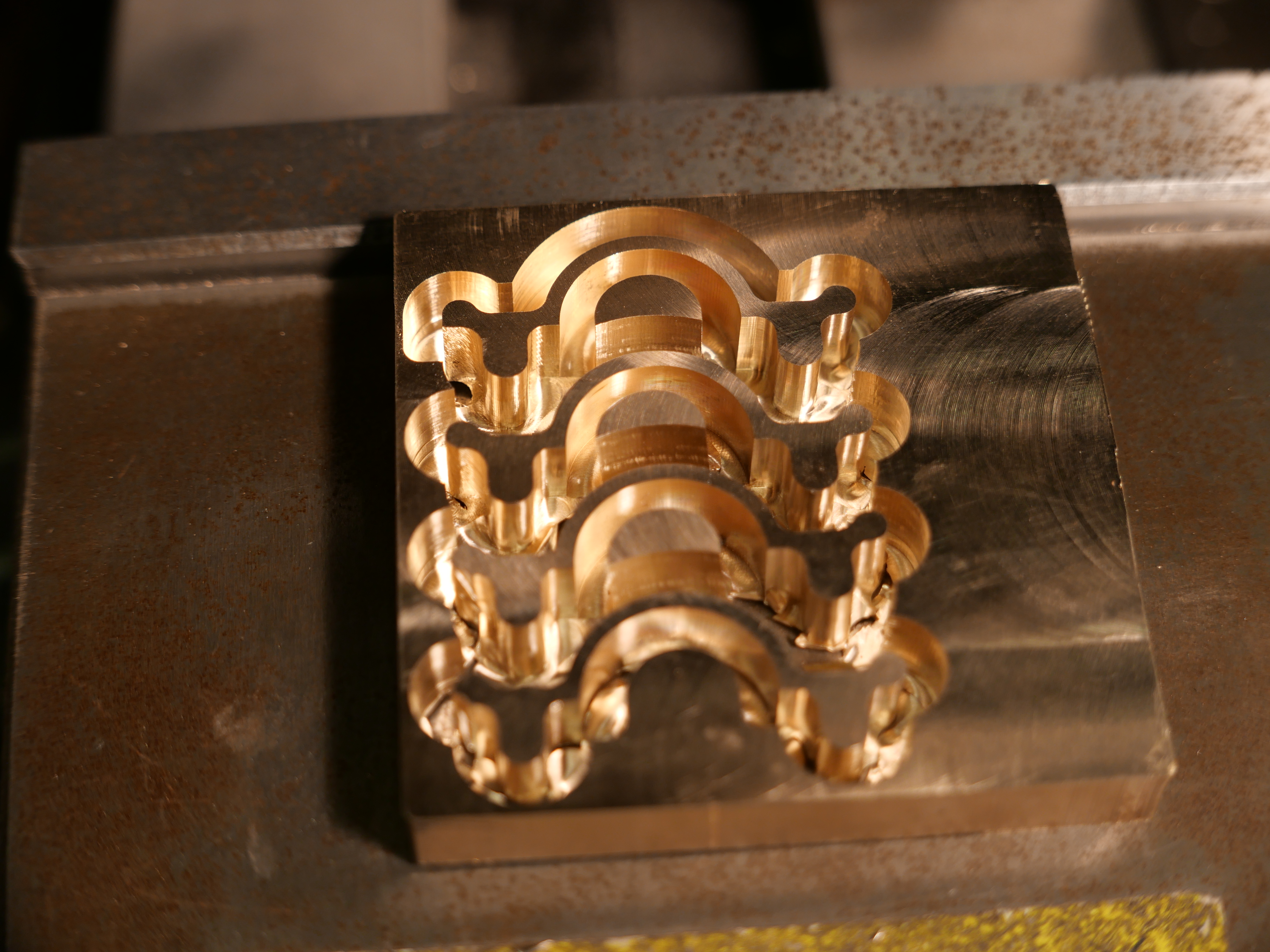
Do I repeat the method, or maybe try something more efficient. Like making a solid block of brass or steel, shape the exterior to dimensions, then hollow the interior? Still pondering that one.
Part of the equation is that the riveting gun died. Not sure what happened. Maybe a blown O-ring? The final few rivets in the above pictures were hammered. My hammering is definitely not as neat as the rivet gun. I do have a rivet gun on order, but they are estimating an arrival date of the END OF JUNE! I cannot wait until then. And the faulty gun is not mine so I feel diffident about pulling it apart and maybe repairing it, maybe really screwing it up.
The last time that I cursed the virus I lost 25% of my readers, so I will just think it.
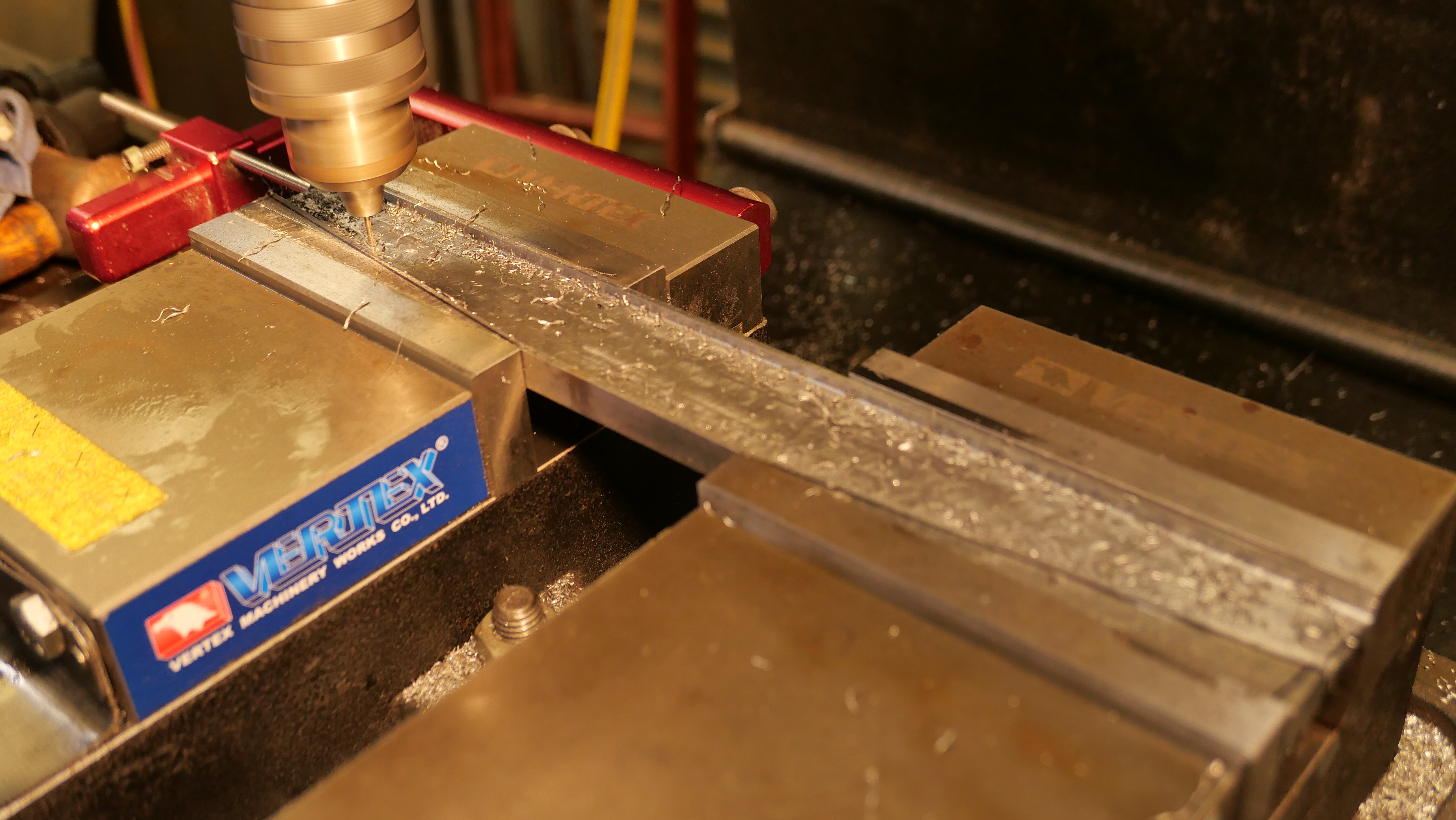
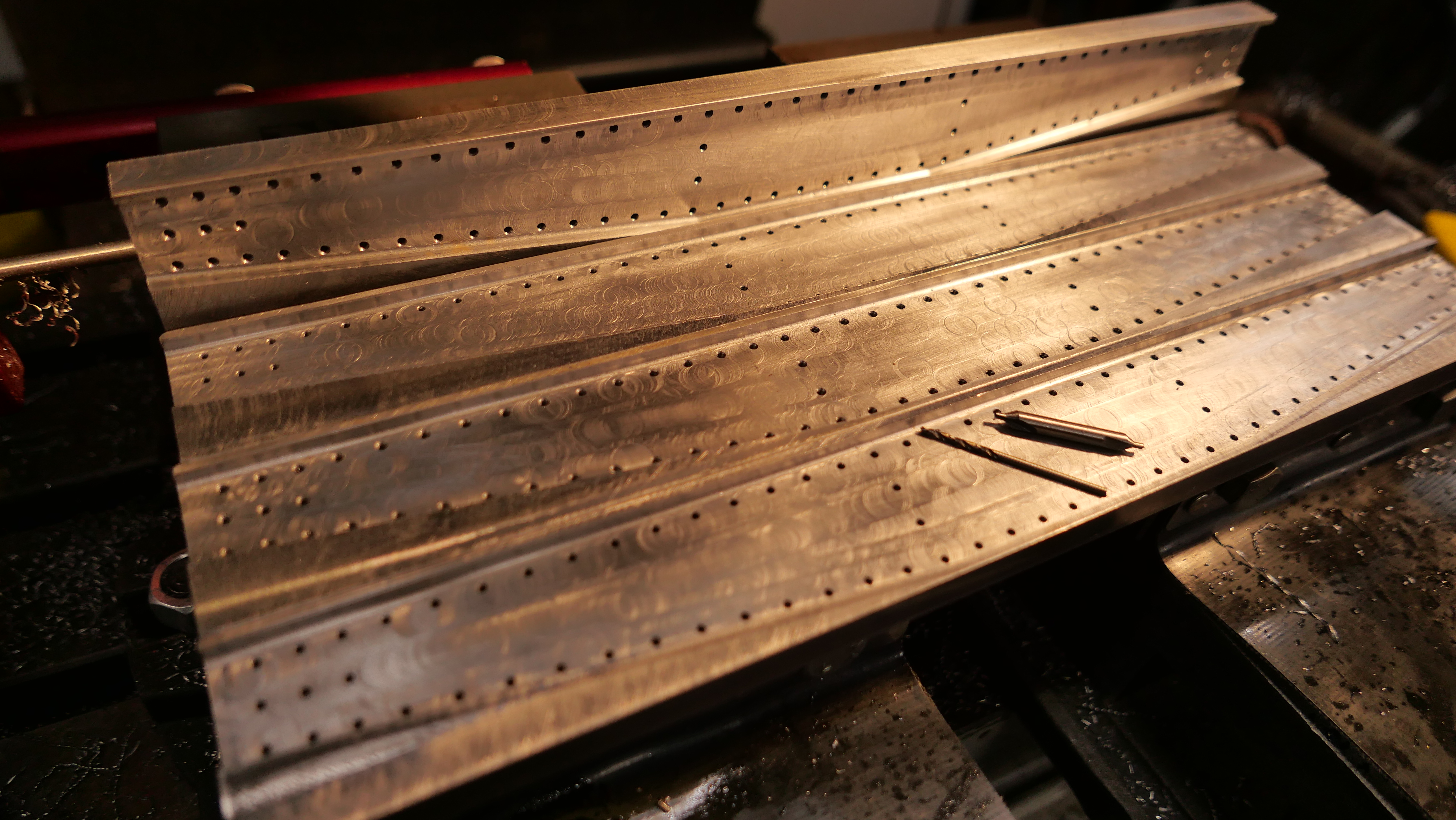
Today I drilled the girders of the chassis under the Armstrong cannon. Each girder has 91 rivet holes. Later I will need to drill more for the gear shafts, and for the center pivot bar.
The holes are 2mm diameter.
The mill drill setup. Re- indicating the vices again took me about 45″.
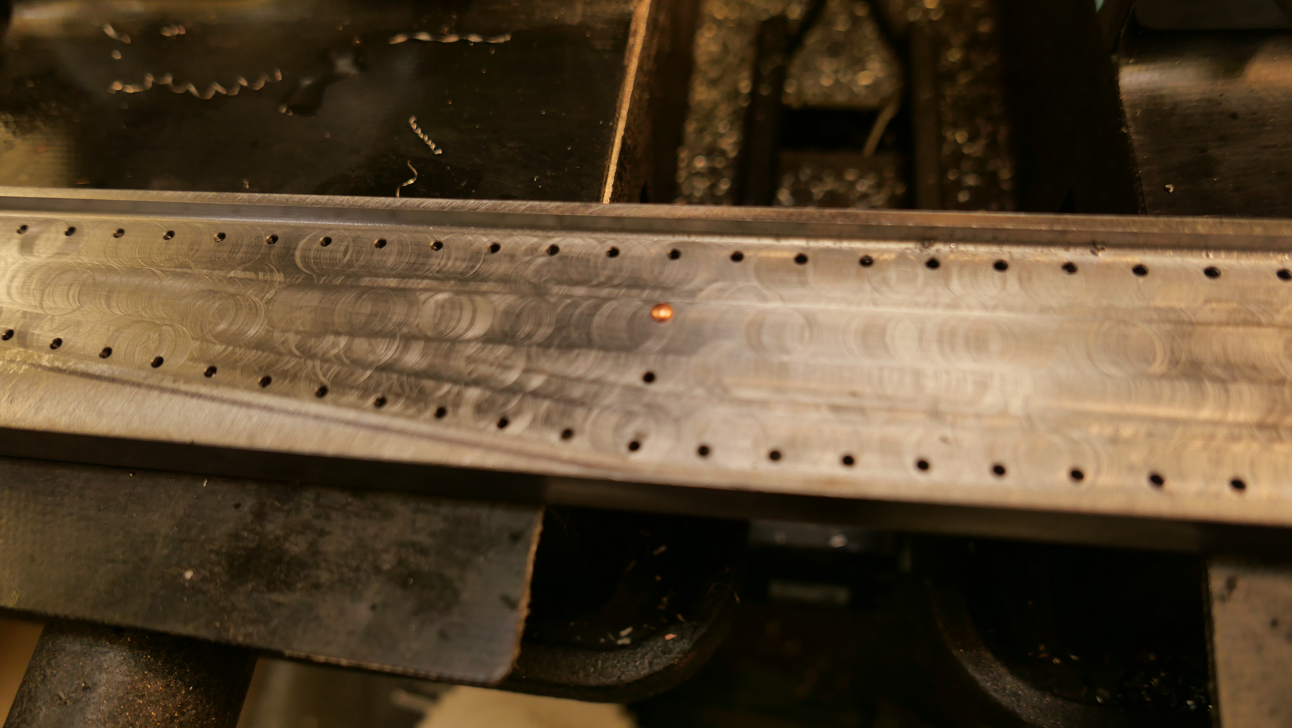
Firstly all of the holes were center drilled, then drilled through. The rivet confirmed a nice sliding fit.
364 holes, through 5mm of steel done with one center drill, and one 2mm drill. That is pretty impressive IMO. More than 1.8 meters of steel with 2 drill bits. And using my olive oil and kerosene lubricant-coolant. And the bits still seem to be sharp.
Each girder took about 28″ to drill the 91 holes. CNC of course. It has been a while since I said it….. “I love CNC”.