johnsmachines

machines which I have made, am making, or intend to make, and some other stuff. If you find this site interesting, please leave a comment. I read every comment and respond to most. n.b. There is a list of my first 800 posts in my post of 17 June 2021, titled "800 Posts"

Tag: metalworking

CNC Lathe conversion -16

The wiring of the lathe is complete.  (Except for limit switches.  They can be added at any time).

Mach 3 is configured.  The wireless hand control is installed and working.  Ezilathe installed and waiting for input.

Some covers to be made.

IMG_4154

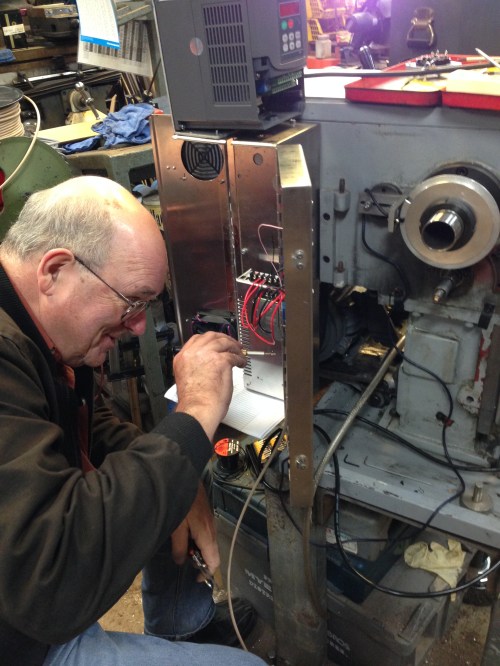
Hook ups in progress.  That’s the faulty VSD on top of the electronics enclosure.  The CNC engineer lost his hair trying to figure out the problem.

Still some testing and fine tuning required.

But nothing much will happen in the workshop for the next  3 weeks.


CNC Lathe Conversion – 8

Continuing the installation of the ball screws, and stepper motors.

I have completely removed the digital read out module and glass slides, and they will not be reinstalled.  Not sure what I will do with them.   They are only a year or two old, and in good condition.  I will probably put them on Ebay.  Same with the old gearbox, carriage apron, and electric controls.

Here are some pics of the plates and blocks which support the ball screws and steppers.

IMG_4089.JPG

This is the steel plate at the headstock end, bolted to the bed.  And the block with the holes is cast iron 42mm thick, to support the leadscrew and leadscrew stepper motor.  It was machined out of an old piece of machinery, hence some unintended holes.   Being cast iron it was fairly easy to machine, but incredibly dirty. Turned everything in the workshop black, including me.  (whoops.   Unintended not PC)

IMG_4087.JPG

This is the block which replaces the gears and controls of the apron under the carriage.  The thick block is cast iron, and the stepper motor support is 20mm thick steel.  Very heavy.

IMG_4086.JPG

This plate is hidden under the carriage.  It secures the lead screw nut.

IMG_4085.JPG

The slot in the carriage had to be widened and deepened a bit, in order to accomodate the slightly fatter and taller cross slide nut.  See the next photo to see the setup for milling the hole through the carriage.

IMG_4084.JPG

A rather confusing photo.  The carriage is clamped to a large angle plate on the mill, and I am enlarging the hole which accommodates the cross slide ball screw.  It was at the limit of what my mill could manage.  An intermittent cut, with a lot of tool stick out.   Not the best way of doing the job, but it worked OK.

IMG_4088.JPG

Plastic covers attached to the stepper motors, and toothed belt pulleys fitted.

IMG_4075.JPG

Checking the centres between the pulleys, using 2 wooden wedges to push the pulleys apart.

IMG_4083.JPG

The underside of the carriage.  The hole and channel at the left side of the picture was machined to accept the larger cross slide screw

So you can see that I have been busy since the last post.

At present the lead screw is at Linear Bearings in Melbourne, having the ends machined to accept the driving pulley, and support bearings.  I did consider doing this machining myself, but decided to leave it to the professionals because of the high cost of the item and the hardness of the material.

Shear Wave Seismic Source

You are probably wondering WTF this is about.

So was I, when I was asked to consider making one.

I gather that researchers and geologists use them to work out what is going on in a geological sense underneath our feet.

Seismic waves are generated from ground level, and instruments pick up frequency changes and time delays, providing information about what is happening below.

The seismic wave generator has the following requirements…

  1. it is anchored or spiked to the ground surface

2.  the spikes must be able to penetrate all types of ground surfaces, including asphalt, and be removable from the ground, and from the device.

3. it must be transportable by hand i.e. no more than 20-25kg

4. it must withstand thousands of impacts from a sledge hammer, in 2 directions

5. it must be  durable, repairable and not too expensive

6. the user must be able to stand safely on the device, while swinging the sledge hammer

7.  it must not generate sparks in some situations

So I have been thinking about these requirements, and I have produced a plan which has been accepted by the client.

Photos of the project next post.


1779 Naval Cannon Scale Model

It is almost 2 months ago that I started this model.

I thought that it would take 3 or 4 days!

Anyway, here it is.

It will look interesting on the mantelpiece.

cannon - 3.jpg

Note the hinge and square bolts and keys on the trunnion straps.

cannon - 4.jpg

A good view of the elevating apparatus, the quoin.

cannon - 6.jpg

A trunnion, trunnion band, trunnion bolts and key.

cannon - 7.jpg

Powder pan and touch hole.

cannon - 8.jpg

The underbelly

cannon - 2.jpg

It goes on display at the Geelong Wooden Boats Show next weekend.


1779 Cannon Bling

cannon - 3.jpg

Rings for attachment of ropes & pulleys, nuts and bolts, wheel pins and ferules, all made of brass in my workshop.  Note the square nuts.  Since this is a scale model, the originals would have been 50 x 50mm(2″x2″).

cannon - 7.jpg

The round bits are flat head bolts which secure the rear axles.

cannon - 1.jpg

Making the rings.  2.4mm (3/32″) brass wire is annealed by heating red hot, then wound tightly around a 3mm bolt.  The resulting helix is slit to form individual rings.


cannon - 2.jpg

The rings are flattened and adjusted using heavy pliers, then silver soldered to the threaded rods.  The hole in the smallest ring is only 3mm diameter.

cannon - 4.jpg

I intend to allow the brass to tarnish and darken.  The bright new brass is, I think, a bit glitzy.

PROTECT YOUR SAUSAGE

Watch this video to see the future of circular saws and other dangerous woodworking and metalworking tools.

IMG_2830

This is the electronic unit which senses the human flesh touching the blade, and activates the heavy spring loaded chunk of aluminium, jamming it into the saw blade. The unit costs about $100, and the saw blade is invariably wrecked, with teeth being knocked off. But hey, would you rather lose a finger or a hand? I am told that if the unit is actually activated in preventing an injury, that Sawstop will replace it free of charge.  The unit can only be fitted to machines which are designed for it.  It cannot be retrofitted to older machines. 

CON RODS for TRIPLE -2

The con rod shafts have a taper of approx 1.5 degrees.  I turned the shafts between centres, using a tangential tool. The HSS cutter has a round cross section which gives a good finish, and automatically fillets the joins.

The con rod shafts have a taper of approx 1.5 degrees. I turned the shafts between centres, using a tangential tool.(a Diamond tool holder from Eccentric Engineering).  The HSS cutter has a round cross section which gives a good finish, and automatically fillets the joins.

IMG_2673

Of course left and right hand tools are required to do the whole taper.

Another jig! The con rod is difficult to hold accurately for milling, so I made a jig to assist. 10mm aluminium plate, with a cut out section to accept the con rod casting.

Another jig!
The con rod casting is difficult to hold accurately for milling, so I made a jig to assist.
10mm aluminium plate, with a cut out section to accept the con rod casting.

IMG_2675

The jig had to be made as accurately as possible. So it was milled square and parallel, then centre pins were installed to hold the casting by the previously drilled centres. A further pin with a sharp point was installed to stop the casting from rotating during the drilling and reaming for the gudgeon pin. That gudgeon pin hole was continued through the jig, so a large pin could be inserted to really hold the casting securely. It also allowed an accurate 180 degree rotation of the casting.

IMG_2676

A bit clearer with the swarf swept away!

IMG_2677

You can see the gudgeon pin in place, while further surfaces are milled.

IMG_2678

Close up of the jig and my metal workers’ dirty hand.   Just as well there is no more gynaecology.

IMG_2679

Progress!

IMG_2680

Not a clear shot, but here I am using the flutes of a milling bit to smooth the flat section under the gudgeon pin. Not ideal but it worked OK.  Tomorrow I plan to round off the external surfaces and mill the slot for the cross head.    Not much to show for a full day in the workshop, but it was fun…

TRIPLE CYLINDER HEAD CAPS

IMG_2566

The head caps sitting in position.

Turning these fairly simple pieces should have been a doddle. Trouble was that they are relatively thin and soft and holding them in a three jaw chuck on the lathe was OK, until the rather sharp tool got pulled into the work. The cutter jammed, the workpiece was pulled out of the chuck and thrown across my workshop, with a a lot of superficial damage to the workpiece.
Fortunately, there was enough material remaining to machine out the dents and cuts. Also, it forced me to make a jig to hold the workpiece securely. Since the head caps are all different sizes, I had to change the jig dimensions after each head was machined, which was time consuming, but the method worked well with no further hitches.  Also, I changed from a tangential, sharp, high speed steel cutter, to a neutral rake carbide (and therefore less sharp) one, and no further dig ins were experienced.

IMG_2568

The jig for turning the reverse side of the cylinder heads, and the underside of the low pressure head (the biggest one)


Next I will drill and taps the holes for the small bolts which secure the head caps.  All 56 of them.  I sense some more CNCing in my near future.

Cylinder Bases. Lathe or milling machine?

I read an expert treatise on making a double expansion steam engine, and I imagine that the comments applies to triples also.  One aspect emphasised the importance of accuracy in making the cylinder bases.  The parallelism of the surfaces, the concentricity of the piston rod hole and the other circular elements, and the thickness. The usual method for making these items is to turn them in a lathe with a 4 jaw chuck, then to reverse the item in the 4 jaw to turn the other face.  It is possible, but very fiddly and time consuming, and relies on expertise, patience, good eyesight, and a good lathe.   All of which are in short supply around here. A triple expansion steam engine requires 3 of these base plates, and while there are some common dimensions, the cylinder bores are all different.  Many of the screw holes are common to the 3 plates.  The thicknesses are all the same. To shorten this rather boring epistle, I decided to have a go at making the base plates on the CNC mill.  Given my previous muck ups, broken bits, crashes, this was a courageous decision, as evidenced by having to bin the first effort.  But the next 3 all seemed to work OK. First I studied the plans and noted the common elements, then I made a jig, with holes drilled at the common positions.

IMG_2543

The underside of the jig, showing the 5mm centre hole and the counterbored holes at the attachment points.

IMG_2544

The topside of the jig, after the first and second baseplates were drilled, thicknessed and shaped. The jig needed to be made very accurately, to retain position of the workpiece after it was reversed, so both faces could be milled. I am told that CNCers build up a collection of jigs over time. They are rarely used again.

IMG_2531

CNC milling the central boss. 20.48mm diameter, and accurate. Note the red positioning device, enabling the workpiece to be removed to check measurements, then replaced exactly in the same position.

To see a video of the CNC mill cutting the external profile click on the link below http://youtu.be/m0d5yuX96Uc

IMG_2541

The cylinder baseplates screwed to the columns. Some trimming of the column tops is required. The baseplates are centered accurately, as far as I can measure. Note that the central jig separating the columns has been removed, and the baseplates are now holding the column tops in position. The columns appear to be lining up correctly.

IMG_2538

The next example of using the CNC mill to perform a task which is normally done on the lathe. The mill cutter is travelling in diminishing circles, producing a central boss, and a flat surface.

IMG_2540

The boss finished to size (10mm dia) and flat surface.

BTW.  In a previous post I mentioned a 1 mm inaccuracy in a CNC milled part.  It happened again when I milled the first base plate, which ended up exactly 2mm smaller than programmed, and had to be re-made.  This time I discovered the cause of the inaccuracy….   I had used an 8mm milling cutter, but had forgotten to tell the CNC computer that I had changed from using the 6mm cutter.  The CNC machine did not notice the change, and cut the part exactly as instructed, very accurately, 2mm smaller than intended.  CNC machines are incredibly clever, but very very dumb.  They do exactly as instructed, even if the instruction is wrong.

Buying Tools and other stuff at a swap meet.

Today I drove with a friend to Ballarat, Victoria, Australia to the biggest swap meet in the Southern hemisphere, maybe the biggest in the known universe.

It is located on an aerodrome in country Victoria.  Approx 2500 stall holders selling stuff from shed cleanouts, factory close downs, farm sales, and some commercial sellers.

A lot of the stuff on sale seems to be total junk, with the vendors sitting around enjoying the sunshine, the conversations, the beer and barbeques.  A lot of them stay in tents and caravans on site.  But there are many gems and bargains, and that is the reason I find myself drawn back to the event, annually for the past 4 years.

The atmosphere and mood is relaxed and pleasant.  A fair bit of good natured haggling and bargaining goes on.

You do have to keep an eye out for kids on bikes whizzing about.  It is supposed to be a car free zone, but I noted far too many vehicles driving about raising dust.  The organisers need to get on top of that issue.

I was also a bit peeved to have to pay $3:50 each for a small plastic bottle of water.  It was a hot day, and several of these were required.  The price was feasible because there were no other visible sources of drinking water.

But I was very happy with my purchases.  Photos following.

IMG_2499

Hats, sunscreen, and fluids essential. 34 degrees C.

IMG_2501

Amazing eclectic variety of stuff on sale.

IMG_2500

I estimate that I walked 10km checking out about 50% of the sites. Too many to see in one day.

SOME OF THE STUFF WHICH I BOUGHT.  IT REFLECTS MY OWN INTERESTS RATHER THAN THE VARIETY OF ITEMS ON SALE.  MY FRIEND BOUGHT A HEAP OF PARTS FOR HIS MINI MOKE.  THAT IS HIS PARTICULAR INTEREST.

IMG_2502

A heavy duty, well constructed welding earth clamp for $10.

IMG_2504

Some bronze manganese welding rods for $15. I will check their machineability.

IMG_2505

A miniature internal threading tool with inserts. Expensive at $130, but good value.

IMG_2506

A 1″ m3 step drill (new), and a used but good condition 1.5″ M4 drill bit. $30 total. Great value.

IMG_2509

2 cobalt 9/16″ drill bits for $6. Only one size available. Amazing low price.

IMG_2522

A pair of razor sharp Japanese wood chisels. Pricey at $70, but the conversation I had with the Japanese cabinet maker who was selling them, was priceless. The handles are rosewood and oak. The steel is laminated, similar to samurai swords. I look forward to trying these.

W

A Mamod steam tractor. It seems to be in reasonable condition, and complete. I told SWMBO that it is a present for a grandson when he is a bit older (2 years old now), but we will see. I really like it myself. Is 64 too old to be playing with toys? Was said to be in working condition, but I expect that some renovation will required.  Price not for disclosure to SWMBO.

IMG_2508

This was the most interesting purchase. 3 “Model Engineer and Amateur Electrician” magazines from Sep to Dec 1900. $5 each. The articles about “using electricity in the workshop” were sobering. It was nice to see articles about lathes apart from Myford discussed. (Drummond most common). Not sure where these magazines will end up. They should be on display, or in a museum.


GEELONG SOCIETY OF MODEL AND EXPERIMENTAL ENGINEERS ANNUAL EXHIBITION 1

Steam truck, built by Thomas Lord.  See following videos

Steam truck, built by Thomas Lord. See following videos

The GSMEE held its annual exhibition of projects by members and friends, on the weekend of 15-16 November 2014, at Osborne House, Swinburne Ave, Geelong North.
I will post some pictures and videos of some of the superb model engines, boats, ships, tools, aero engines, and even a full size road legal registered steam truck, pictured above. Due to the size of the files and the crap Internet connection available here, I will spread the post over several days.

To continue with the incredible steam truck, made over the past decade by Tom Lord, see the following videos.  (sorry, no luck with the upload. I will try again tomorrow)


Beam Engine Driving Wheel 2

The aluminium disk was drilled then reamed to 19.05mm (3/4")

The aluminium disk was drilled then reamed to 19.05mm (3/4″)

IMG_2207

Then a shaft was pressed into the disk. The shaft is the same as the shaft on the beam engine, in fact it is from the same stock. It was centre drilled at the ends in preparation for turning between centres, and shaping the driving wheel.   This should result in a wheel which runs true and does not wobble when installed onto the beam engine. 

TAPPING HOLES. BOLTON 9. (Triple Expansion Marine Steam Engine)

Today I drilled and tapped the holes for the bolts which secure the crankshaft main bearings.  I had accurately marked the bearing mounts  in the previous session (see previous photos), and calculated and recorded the DRO (digital read out) position for each hole.  So going back to that position for each step in the process was easy and quick.  The steps today were centre drilling, drilling the 3.3mm holes, and tapping the 4mm threads to a depth of 20mm.

Centre drilling is done with a centre drill bit in an accurate chuck in the milling machine.  Centre drill bits are inflexible and will not wander over the work like an ordinary twist drill bit,  The centre drilled hole is deep enough to create a chamfered edge to the hole.  All 12 holes are drilled with the centre bit, then all 12 drilled with the 3.3 mm bit, then all 12 are threaded.  The DRO positions the work within 0.005mm each time, and the repositioning is very fast, much faster than going to a position doing all 3 processes, changing the bit for each one, then moving to the next position.

The threading was done with a Tapmatic 30 tapping head in my milling machine.  See photo.  This takes about 10 minutes to set up, but the tapping process for the 12 holes then took about 5 minutes.  I use Rapid Tap lubricant for tapping, even in brass.  I guess that manually tapping the holes would have taken about the same time, but it was so satisfying to see the Tapmatic do its stuff.  I use the Tapmatic for any tapping job involving more than about 8-10 holes.  Fewer than that it is quicker to do them manually.  The Tapmatic has a adjustable clutch.  I have never broken a tap in the job using this machine.

Incidentally, I have decided to use nuts and bolts and screws and studs in preference to metric cap screws for this model.  The appearance wins out over practical expediency.  So why the metric threads for this job today?  The specified thread was 5/32″ which is 3.96mm, so I decided to go with the 4mm metric, for which I have the tools already.


Tapping the main bearing blocks using the Tapmatic and Tap Magic.

Tapping the main bearing blocks using the Tapmatic and Rapid Tap.

TRIPLE EXPANSION MARINE ENGINE 2

Reducing the width of the aluminium plate to 140mm, so it will fit into my milling vice

Reducing the width of the aluminium plate to 140mm, so it will fit into my milling vice.  The plate is clamped to an angle plate.

Squaring the ends.

Squaring the ends.

IMG_2153

The base plate bolted to the aluminium plate. Care was taken to fix the brass base centrally and parallel to the aluminium. The fixing bolts are 3mm cap screws, and the holes through the brass plate are 3mm, so even if the brass base is removed, it will go back on in exactly the same position.

IMG_2154

I finished the day by making a spur gear for my brother’s lathe.


The gear attached to the shaft using Loctite.  If the Loctite is inadequate, the gear can be pinned to the shaft.   In the post tomorrow, to Townsville QLD.

The gear attached to the shaft using Loctite. If the Loctite is inadequate, the gear can be pinned to the shaft. In the post tomorrow, to Townsville QLD.  The photo shows why metalworking is an unsuitable hobby for a gynaecologist.

TRIPLE EXPANSION STEAM ENGINE 1

The base casting.

The base casting.

The base of the base, machined flat

The base of the base, machined flat

The base, with 6 pillar mounting areas machined parallel & coplanar, and the crankshaft mounting blocks after an initial skimming.

The base, with 6 pillar mounting areas machined parallel & coplanar, and the crankshaft mounting blocks after an initial skimming.  Slots for big ends roughed out.  2 hour first machining session.  2998 hours to go?

After carefully examining the base casting, and scrutinising the plans to discover all of the dimensions of the base, I commenced machining on my King Rich mill (Bridgeport clone, NT40 with DRO, an excellent machine). Since the base dimensions are scattered over 3 pages of very complex plans, and I am still relatively unfamiliar with them, I am approaching the machining with great caution. At this stage I am aiming to create some flat and coplanar surfaces, with a margin of material remaining, so I can hold the base flat, without rocking, roughing out the shape, and leaving finishing to dimensions at a later date. I intend to attach the base to a rectangular piece of aluminium, so the aluminium can be clamped or held in a vice, rather than risking damaging the brass casting.

NEXT LAKE GOLDSMITH STEAM RALLY Nov 1-2

The next Lake Goldsmith Steam Rally is on November 1-2, near Ballarat, Victoria, Australia.  Google it for information and directions.

As well as the usual cornucopia of all styles and sizes of steam and other antique engines, including the massive 90 ton working steam shovel, and the working steam sawmill (see older posts on this site for videos), the rally is making a feature of CATERPILLAR machines.

I will be there.  Along with many many other machine addicts.

Beam Engine Ready for Painting

I uncovered the beam engine last weekend, and thought about painting some of the machined parts. I quite like the look of the machined metal and the rough cast surfaces, but some bits really look as if they should have some colour.

The engine itself is almost fully machined.  Just needs things like gaskets, pump hookups, some bolt lengths trimmed.

The copper exhaust pipe will eventually hook up to a steam condensing unit which is yet to be built.  The condensing unit will be housed underneath.

IMG_2079

IMG_2080

I am planning to polish the aluminium base to a mirror finish, and paint the dark cast iron surfaces in a dark green gloss paint. Some items I will electroplate with nickel.

I have no 3 phase power in my workshop at present, due to a failed component in the phase-changer, but it has been repaired and will be reinstalled in a day or so. Then back to the machining. The painting can wait.

CNC MILL 9

IMG_2068
Yesterday I cut some metal on the CNC mill for the first time.
I used one of the canned cycles built into the CNC controller, and faced and squared off a lump of brass which will be used for a hot air engine (The Ridder “bobber”).
Despite multiple readings of the manual, I got confused about which units required minus signs, and which ones the machine automatically assumed were positive and negative, and consequently, despite resting my hand on the emergency stop button in case such a contingency occurred, the head crashed straight into the milling vice, breaking 4 carbide tips and leaving a permanent love bite on the vice as a reminder of my incompetence.
After some expletives deleted, I re-entered the numbers, and next time, the machine went through its motions gracefully, purposefully, and quietly, leaving me with a nicely shiny and squared lump of brass.
It was so impressive, that I repeated the exercise, just for fun.
I had checked the squareness of the mill head to the table, and it was all within 0.01mm in 100mm, so nothing was altered.
I had bought a Z axis probe from CTC Tools in Hong Kong, and that was easy to use and accurate, for $a100.
Next step, to hook up a computer and try to download G code programs. Watch this space.

CNC MILL 6

Help!

I need a wiring diagram for the Extron mill.

It is a Hafco badged machine, but Hafco (Hare & Forbes) do not have wiring info.  The Extron factory in Taiwan has not replied to my emails.  Hare & Forbes apparently contacted the factory, and also drew a blank about wiring info.

That is pretty unimpressive.  The machine is only 17 years old.  In built obsolescence?  Just not worth while supporting older machines?  If it was a US or European machine there would be no problem getting info.  It seems that this Asian factory has a different idea about what constitutes support.  

Fortunately I have an expert friend who will, I am confident, be able to work it out.  


CNC MILL 5 with some more pics

The broken X axis hand wheel.  replacement from China for $a20, including postage....

The broken X axis hand wheel. replacement from China for $a20, including postage….

The replacement folding handle hand wheels arrived from Hong Kong today. I was slightly disappointed in the quality, but then, for $a20 each, including postage, I am not complaining. They are close in appearance to the originals.

IMG_2040

The new hand wheel fitted. On the table is a spare new hand wheel, and the broken one. I am considering machining the new one, to be closer in dimensions to the old one.

IMG_2037

This is the pneumatic draw bar motor and spring loaded engagement gear. It is now functioning!! I rebuilt a badly corroded valve, and remade a gasket, and hooray, it works perfectly. Still to replace the cover which keeps the dust out of the device. That saves $a700+ for a replacement, and gives me confidence to work on these precision items in the future. The motor behind the draw bar motor is the main spindle motor, a 6hp 3 phase motor with a very noisy fan which is another job for down the track. One thing at a time. We are getting there. I have contacted Extron Corp in Taiwan, in the hope of getting a wiring diagram, so I can look at the oil distribution pump and controller and locate the relay, which I suspect will be the culprit. It does feel good to have fixed 2 of the 5 or 6 problems with this machine.

CNC Mill 2

I was on call over the weekend, so I had today off, and spent it in the workshop. It was cold. Jumper plus oilskin cold.
I crow-barred the space for the new mill, levelled the mill with a machinists level. One foot was missing so I turned up a new one… 75mm dia, 16mm thick, with a 20mm dia recess to accept the levelling bolt.
Then I started to tidy up the awful paint job, scraping paint off the machined parts, and using my Dremel to wire brush it off plastic parts. Starting to look more respectable.
Then I found a hand wheel control lever stop made from a rolled tube which had broken off at surface level. It was hardened, as I discovered when I tried to drill it out… changed the drill bit to mush. So I used the Dremel with a carbide bit to grind it out. That worked, but it took a lot of time, and I ended up with an irregular hole which I then drilled out to 5mm and tapped 6mm. I have inserted a temporary 6mm cap screw as the stop, and it works but looks a bit gross. Needs a tidy up.
The 3 phase lead does not reach my converter, so I have to replace it with a longer one. The plug is new, so I will re-use that. I have some 20 amp 4 wire lead, so I will use that. Maybe next weekend I will get to fire it up. Saturday is out though. Geelong – Hawthorn AFL game takes precendence.
I need to make some T nuts to suit the 18mm T slots. They are bigger than any machine I have previously owned. I will tap them to accept 12mm studs, rather than the recommended 16mm studs. I already have the 12mm studs, and I cannot see that I will need the bigger ones. If i was to use the table capacity of 900kg the big ones would be useful.

DIVERSION

I have heard that the castings for the triple expansion marine engine will be arriving in the next week or so. That is good news after waiting since the order was placed in January.
In the meantime, I have bought some castings and partly made components for a Burrell Traction Engine. It is 1.5″ scale, and I obtained some 1.5″ plans from EJ Winter for the Burrell. Unfortunately, one mans’ 1.5″ is anothers’ 1.45″ and the plans are not exactly correct for the castings! What would have been a difficult build, has turned into a very difficult build. So I have put it aside and will tackle it gradually. The plans will be some use, but as well as the difference in scale, there are differences in the designs. So I will have to make it up as I go, to a considerable extent.
My metal working club has promoted a competition for 2014, and it appeared to be a fairly simple build, so that is what I am currently machining. See the progress in the photos below. It is a Stirling heat engine, designed by J Ridders. You can see one working on the Ridders web site http://heetgasmodelbouw.ridders.nu

IMG_1989

IMG_1990

IMG_1991

Almost finished stand for the cylinder fork.

Almost finished stand for the cylinder fork.

IMG_1993

Components made so far

Components made so far

The spirit burner, almost finished.  Copper and brass,  silver soldered.

The spirit burner, almost finished. Copper and brass, silver soldered.

Stirling "Bobber" plans

Stirling “Bobber” plans

Burrell Traction Engine

I bought these Burrell Traction Engine castings and parts off ebay recently, because they were cheap, and my triple expansion engine castings still have not arrived!
The traction engine is 1.5″ scale, and the finished model will be about 500mm long.
The complex copper sheet part in the middle of the back row has been partly riveted and soldered. The sheet steel parts on the right hand side have had some of the fittings bolted to it. I am guessing that 95% of the build is yet to happen.
There were no plans, but Kelly Mayberry at EJ Winter has a 1.5″ Burrell in his catalogue , so I have purchased those plans hoping that they will suit. Kelly tells me that the Burrell is a fairly difficult build, so that is a challenge.
There are hundreds of rivets in this engine, so riveting will be a new skill to acquire.
22 July 2014. The plans have arrived, 9 sheets of them. Like all plans, the initial browse showed a daunting mass of detail. Some of the sheets have imperial measurements, so first task is to convert those to metric. The boiler particulars were upgraded to modern approved standards a few years ago, so they at lest are already metric.
The next task is to get the plans laminated, so they remain readable in the dirty workshop environment.
Then to starting the fun bit… the machining…..
There are many such models, working, on U Tube, and worth a look.

johnsmachines

Castings for Burrell steam traction engine. Castings for Burrell steam traction engine.

IMG_1958IMG_1959IMG_1960IMG_1961IMG_1962

View original post

Burrell Traction Engine

Castings for Burrell steam traction engine.

Castings for Burrell steam traction engine.

IMG_1958 IMG_1959 IMG_1960 IMG_1961 IMG_1962

LAKE GOLDSMITH STEAM RALLY

Today I attended this steam rally near Ballarat Victoria Australia.

The weather was cold and wet, and accompanied by my brother Peter and friend Stuart S, we drove the 2 hours from home.

I had only a vague idea about what to expect, but it was so fantastic that I will be definitely going to future events there.

To explain, Lake Goldsmith is farm land, in pretty undulating countryside.  38 acres have been set aside for steam enthusiasts, and dozens of sheds of various sizes have been put up and filled with workshops and machines.  Many of the steam engines were outside, so we were grateful for the shed displays whenever the rain set in.

There were hundreds and hundreds of steam engines, boilers, traction engines, early kerosine farm engines, vintage tractors, model engines.

There was a working timber mill, cutting huge pine slabs, powered by a superb steam engine.  See the videos.

The star of the displays, is a working 90 ton steam shovel

Redgum steel press

Showing the 80 degree steel knife edge, and the 90 degree V groove in the redgum.
The folded steel is in the foreground

INTO REDGUM

Maybe that’s what I meant with the “Interregnum” post.
This is a 20 tonne hydraulic press, bending 3mm steel.
Nothing too special. Except that the anvil is made of wood.
The bar is 45×45 steel, machined to an 80 degree edge, and that steel bar is pushing into it with all of 20 tonnes. And at the end of it, a nice 90 degree fold in the steel, an not a mark or a dent in the redgum. Redgum is amazing.
I used the wood because I did not have a piece of steel large enough to hand, and I knew from past experience just how tough this wood is. Our house rested on it for 80 years (wooden stumps, changed for concrete due to under ground rotting.)

Another photo follows to show some details.

THE NICKEL PLATED WORKSHOP -2

A few snapshots from my iphone while I was doing the first nickel plating.

THE NICKEL PLATED WORKSHOP

The stainless steel tank was welded up using a mig welder with stainless wire ($150 for 5kg of wire… ouch).  I had some stainless steel leftovers from some benches which I made a few years ago.  The stainless was cut with an angle grinder.  That was easy with the correct blade in a 9″ grinder.  Like cutting butter with a hot knife, well sort of…

The folds in the steel were 400mm long and the steel was 1.6mm thick.  I wondered whether my 20 tonne press would manage.  I made an anvil out of redgum and the blade from a lump of 45 x 45mm steel 450mm long.  The hydraulic press managed to push the fold with some grunting from me.   The wooden anvil did its job superbly, with not a mark or a dent.  Redgum is amazing.

My MIG welding of stainless steel was very ordinary indeed.  I was using gas for ordinary mild steel.  And it is a while since i have done any welding.  The last time I welded stainless I used TIG with the correct gas, and it was OK.  But this was just a quick job and I did not want to spend on a TIG gas cylinder for this one job.  So I just MIGged it and try not to look at the end result.  I am not proud of it.  Also I had to go back a few times to reweld areas which leaked.  In the end I have a useable but not pretty tank 400x200x150mm which will hold 12 litres of electrolyte.

See the next slide show post of the electroplating setup.  

My friend Phil who had done the zinc plating came around and together we followed the Jane instructions.  Our first effort was not perfect.  The plating was nice and shiny, but it was not even. See the lathe tool in the slide show.   Reason?   Amps too high?  Temperature too high?  Electroplating too long?  Work not well enough prepared? All of the above???   Anyway, next time, I was scrupulous with the degreasing, held the temperature to 50-55c, kept the current below 2 amps, and the result was much better, although still not perfect.   More pics later.  A quick rub with Scotchbrite resulted in a lovely smooth silvery finish.

I cant wait to get back into the workshop.


Electroplating

A friend recently purchased a kit for electroplating small metal items with zinc.  I was a bit skeptical about the value of such a kit, but after some urging I gave him a small tool which I had de-rusted by soaking in “Evaporust”, for him to demonstrate the effect of zinc plating.

Well, was I impressed!  The tool, ( a multi pronged punch) came back gleaming silver, and the brand which previously was indecipherable, was now quite clear.  And being zinc, it will not rust again, for a very long time.

Now I was looking at many items in my workshop, with which I was/am fighting a losing battle to prevent rusting, and which I could electroplate.  Also, various steel components on my engines, which were showing early signs of rust.  Of course they could be painted, but I like the metal look.

My friend had bought the zinc plating kit, so I ordered the nickel plating kit.  Nickel plating is also rust proof, but is is very hard with anti wear properties, and can be polished to a high shine, similar to chrome.  It is also used to increase the dimensions of parts (by tiny amounts, but often that is all that is required).   

The kit has arrived,  and I am currently welding up a stainless steel tank.  To make the tank I first had to make a sheet metal folder.  I had searched the net and Ebay for a suitable tank, but could find nothing the right size.  I even went to the local tip shop, because they have a lot of dumped stainless steel sinks, but nothing in the size I wanted.  

The folder is made, the tank is almost finished, and first nickel plating to happen today.  Photos to follow.  Watch this space. 

BEAM ENGINE, FIRST RUN, ON COMPRESSED AIR.

To see the video of the beam engine running, click on the Youtube link on the previous blog entry.

In order to make the video without the compressor noise, I turned off the compressor and ran the beam engine off the tank full of air.  It did not take long to run out of air pressure, as you will see in the video.

Also, engine is still rather tight, but I expect that the motion will become smoother as the engine is “run in”.

The governor is yet to be linked to the throttle valve, so the engine speed varies substantially.

Watch this space for the beam engine to be run on live steam.

Beam Engine steam pipes made and installed

Machining the flywheel